Bristol Pegasus II.L and II.M
Automatic Throttle Control, Starter
Compiled by Kimble D. McCutcheon
Published 13 Feb 2025
| Part 1: Specifications | Part 2: Description |
| Part 3: Supercharger, Lubrication | Part 4: Accessories |
| Part 5: Magnetos | Part 6: Carburettor |
| Part 7: Automatic Throttle Control | Part 8: Starter |
Automatic Throttle Control
|
|
|
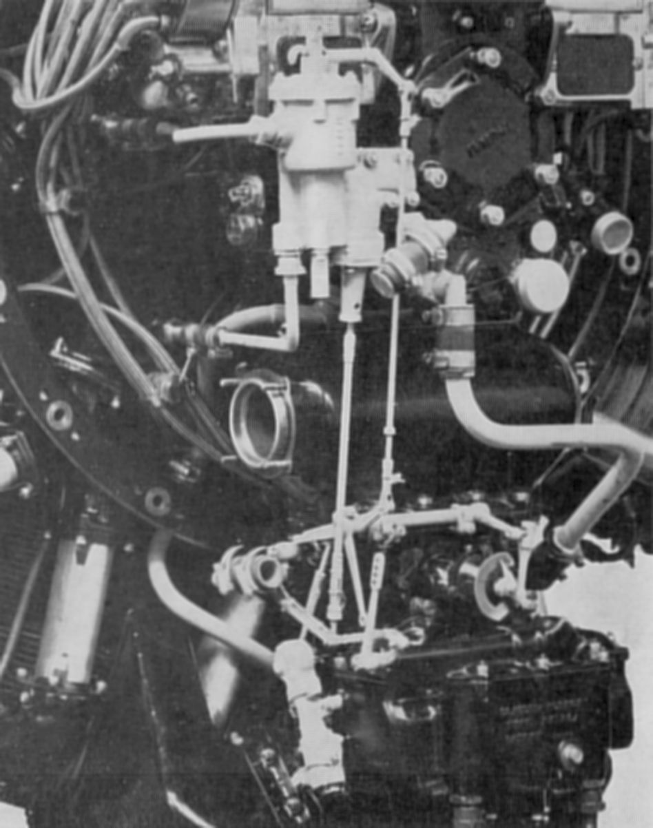
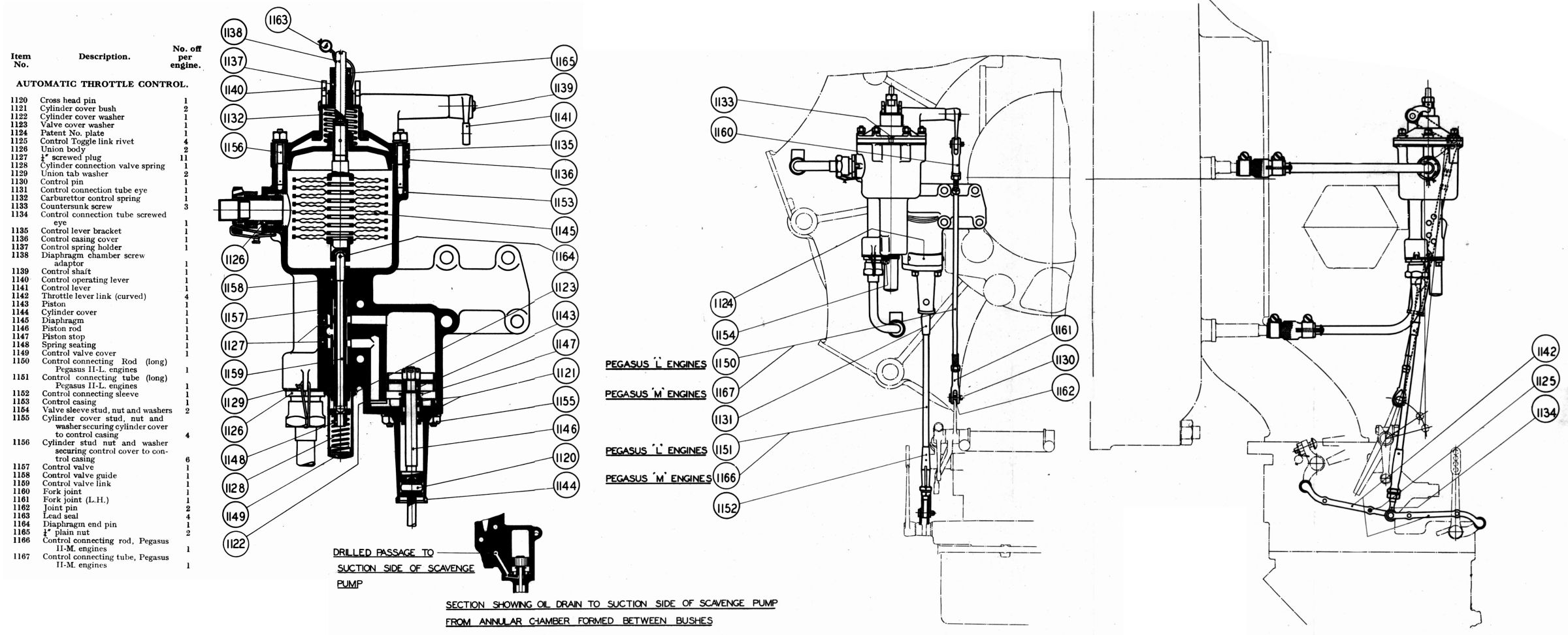
| Fig. 84. Operation | Installed | Drawing |
Naturally aspirated engine power is directly proportional to atmospheric pressure, which causes engine power loss with increasing altitude. In order to maintain a constant manifold pressure, Pegasus engines were fitted with a centrifugal blower between the carburettor and engine induction system. The blower was capable of maintaining sea-level manifold pressure up to the rated altitude. An engine fitted with a centrifugal blower or supercharger must not be opened up to full throttle on the ground, otherwise detonation and engine over-stressing would occur due to the increase in power with the positive manifold pressure created by the blower unit. Therefore, when using a supercharged engine in an aircraft, the pilot must progressively open the throttle during climb to obtain the maximum permissible engine power, the extent of throttle opening being indicated by the manifold pressure. In order to relieve the pilot from manually operating the throttle to obtain this constant manifold pressure, and also to prevent the engine being operated at a greater power than it was designed to withstand at ground level or below the rated altitude, an automatic throttle control was fitted to all Pegasus engines with centrifugal blowers.
Operating Principle
The automatic throttle control consisted of a specially constructed diaphragm enclosed in a chamber, and subjected to various induction system pressures. Diaphragm movement was transmitted to a piston valve of a small servo motor operated by the engine main oil supply. The servo motor piston was coupled to a toggle mechanism that interconnected the pilot's lever with the carburettor throttle. In order to obtain increased takeoff power the control was fitted with an override device, which increased the boost pressure and automatically enriched the mixture strength to prevent detonation at increased boost.
Description
Two union connections on the unit body connected the diaphragm chamber to the engine induction system. Inlet and return oil passages were drilled across the unit body and corresponded to oil ducts on the rear cover to which it was attached, thereby eliminating external oil pipes from the main oil supply. The piston rod was connected to the throttle spindle by toggle links that were anchored to the pilot's lever and to the carburettor throttle. In order to prevent oil leakage from the servo motor cylinder, two bushes were fitted to the piston rod; the center chamber between the bush was connected to the scavenge pump suction side and was therefore under suction.
The diaphragm was specially constructed to ensure accurate and reliable control unit function. It was built up with ten carbon steel capsules , specially heat-treated and tempered. The plates were nickel-plated and all joints soldered and reinforced with spun-on beading. The assembled diaphragm was exhausted by means of a vacuum pump but a small percentage of air was left in for temperature compensation.
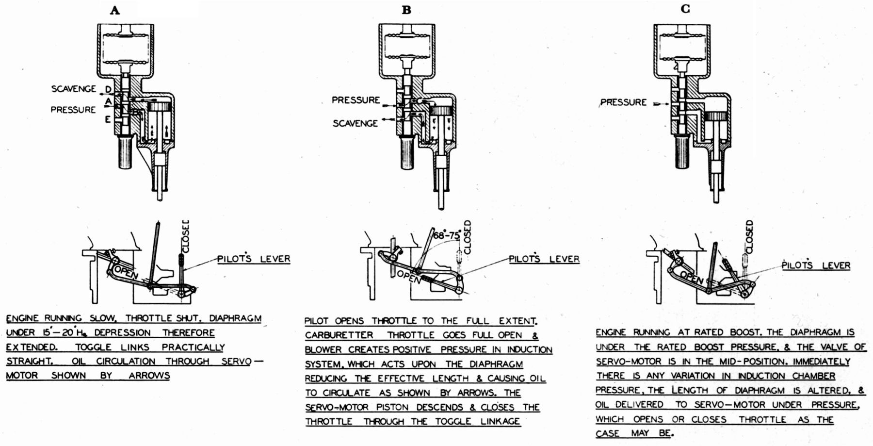
Figure 84 depicts the three key positions of a functioning control:
A. Engine running at slow speed and throttle practically shut. Suction in the induction system, which was acting upon the diaphragm, was considerably below atmospheric pressure (15 – 20 inHgA) and therefore the diaphragm was extended and the servo motor sleeve valve was in the down position; oil pressure was fed to the piston underside, which was forced to the top of the cylinder, straightening the toggle mechanism and opening the throttle.
B. Engine opened up to full throttle by pilot. When the pilot fully opened the throttle the control the manifold pressure increased above atmospheric pressure due to the centrifugal blower unit. The diaphragm compressed and the servo motor sleeve valve moved to the upward position, which directd the oil pressure to the piston top, actuating the toggle mechanism and closeing the throttle thereby reducing the manifold pressure.
C. Engine running at normal boost. When the engine was running at rated boost and being controlled by the unit, the diaphragm was in its normal condition regarding pressures, the sleeve valve was in the mid-position and the piston was not subjected to any pressure, only acting as a dash-pot for the toggle mechanism. Upon a manifold pressure variation from the rated boost the diaphragm operated the sleeve valve, causing the piston to move and adjust the throttle through the toggle links until the rated boost was again maintained.
Servo Motor Valve. The valve port timing was the most important factor governing the satisfactory control function; with the valve in the mid-position a movement of only 0.0015"in either direction made the servo motor piston move from one end of cylinder to the other.rposes.
Eclipse Inertia Starter
 |
 |
 |
 |
 |
| Hand, Electric Starters | Hand, Electric Parts | Crank Handle | Sectioned Diagram | |
This starter was supplied in the Type XI Hand Operated version and the Type XI Electric version. The starter used energy stored in a flywheel revolving at high speed. The flywheel motion was imparted either by hand cranking or by electric motor. The flywheel energy was then imparted to the engine crankshaft when actually starting the engine.
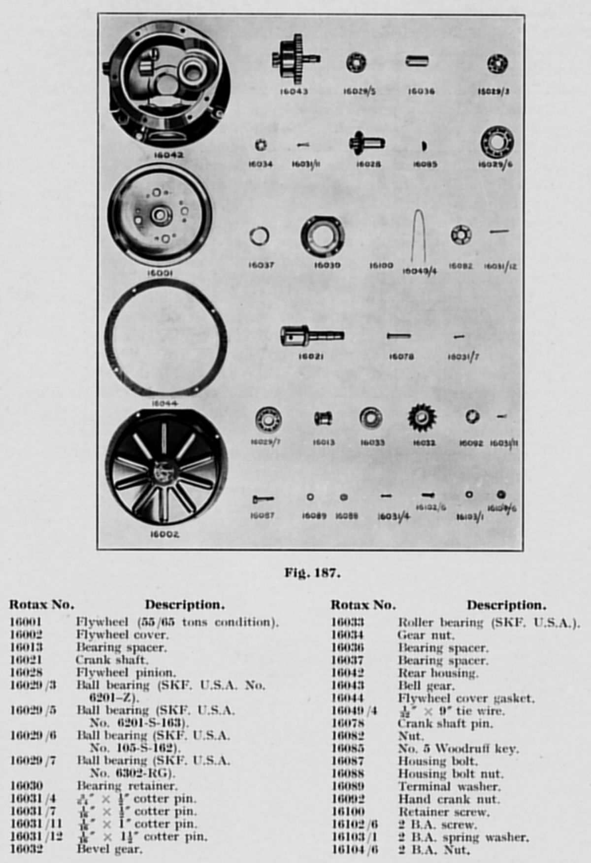
Description
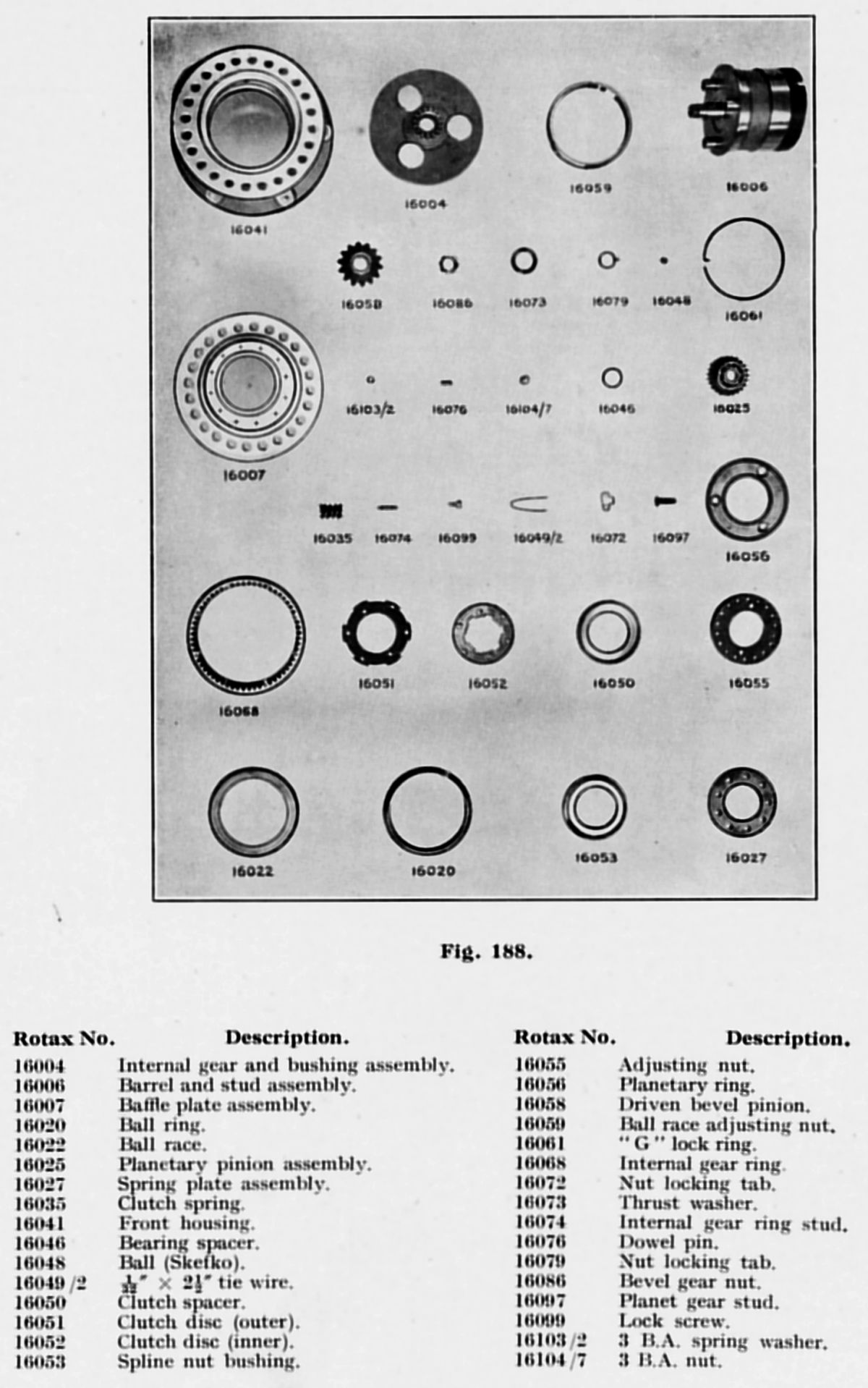
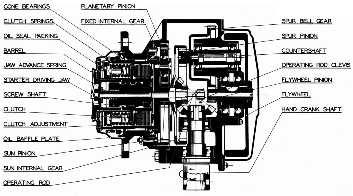
The hand crank drove a pair of bevel gears connected to the driving barrel upon which were mounted planetary pinions. These pinions rolled within the fixed internal gear imparting motion to the sun pinion with which they meshed. Integral with the sun pinion was an internal gear that drove a spur gear and integral spur bell gear. The flywheel was driven by this gear through its pinion. The ratio between the starting handle crank and the flywheel was 150 to 1, thus with a cranking speed of 80 rpm a flywheel speed of 12,000 rpm was attained. The energy thus stored in the flywheel was transmitted in the reverse direction to the driving barrel. The ratio in this case from the flywheel to the engine driving dog was 130 to 1. The barrel formed the outer member of a torque-overload multiple-disc release clutch with adjustable spring pressure. The inner or driven member of this clutch engaged, through its internal threaded bore, with a sliding screw shaft splined to the starter driving jaw at its outer end. When the engine was to be started and the requisite flywheel speed was obtained, a compression spring advanced the driving jaw to engage the engine crankshaft jaw. The jaw could, however, be withdrawn by direct pull from the operating rod, if for any reason the engine did not start and came to rest with the jaws in mesh. When the engine starts, the crankshaft jaw rotation automatically disengaged the starter jaw.
Installation
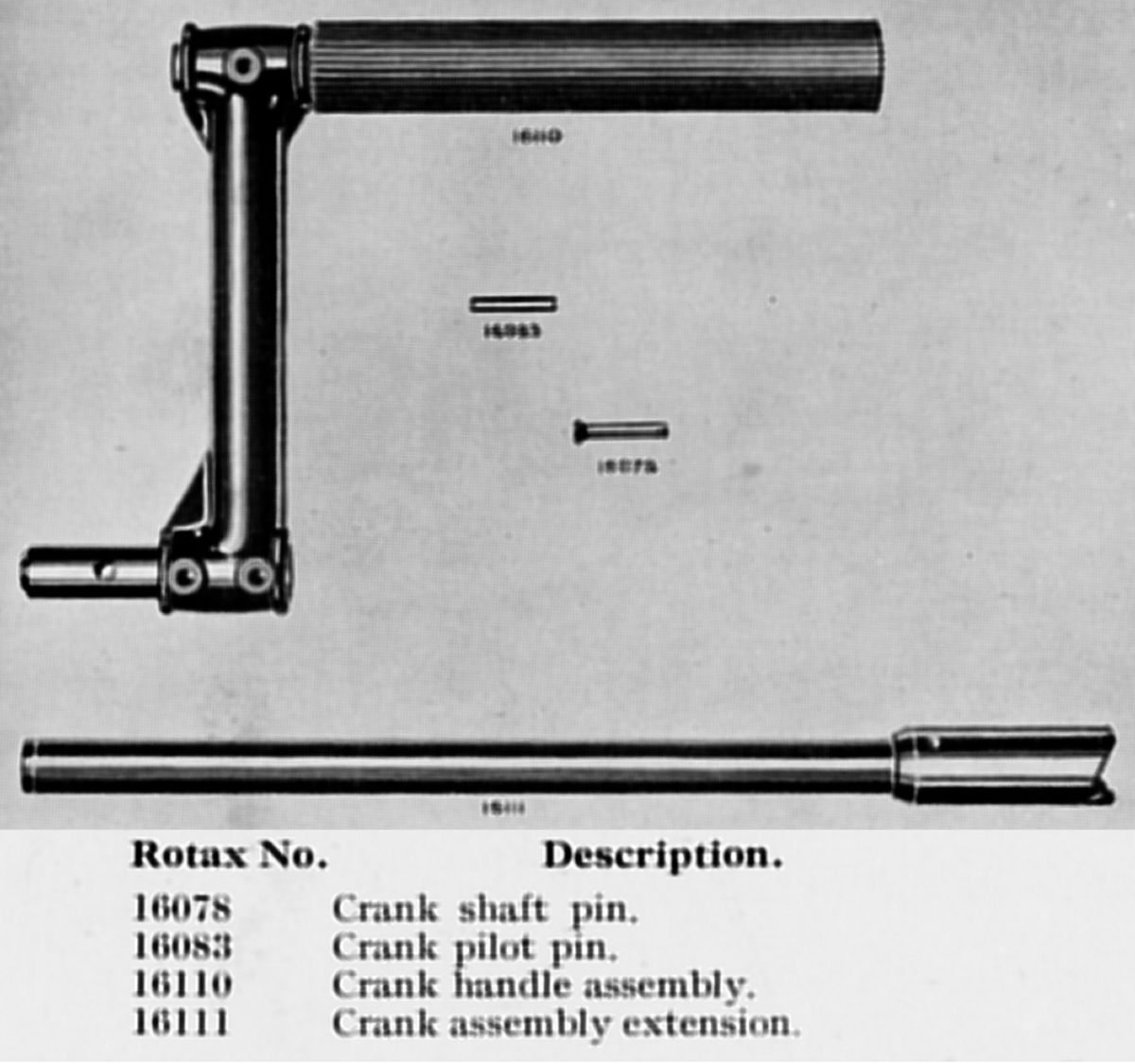
The Eclipse Series XI Inertia Starter was fitted so the operator could rotate the crank handle in an anti-clockwise direction with minimum of effort. To facilitate installation the starter flange had 24 holes and since there were 6 equally spaced securing studs on the engine, the hand cranking shaft could be adjusted to the most convenient position in varying angles of 15°. The shaft angle was set to enable the operator to have the best possible foot-hold and to stand upright.
A spherical bearing was used on the hand crank shaft so that any resistance due to misalignment was eliminated. This bearing was provided with a grease nipple and greased after every ten hours flying. The linkage that engaged the starter claw was operated by a rod or wire provided by the installer. This rod could be located either directly behind the engine or to the side, as the operating lever was provided with two arms at right angles. The crank was to be turned slowly at first, without applying any great effort, and as the speed increased a greater force was to be exerted, until it reached 70 to 80 rpm The time taken to attain this speed was approximately 30 to 45 seconds.
Send mail to
![]() with questions or comments about this web site.
with questions or comments about this web site.
![]()