Bristol Pegasus II.L and II.M
Magneto, Carburettor
Compiled by Kimble D. McCutcheon
Published 12 Feb 2025
| Part 1: Specifications | Part 2: Description |
| Part 3: Supercharger, Lubrication | Part 4: Accessories |
| Part 5: Magnetos | Part 6: Carburettor |
| Part 7: Automatic Throttle Control | Part 8: Starter |
Magneto
|
|
|
|
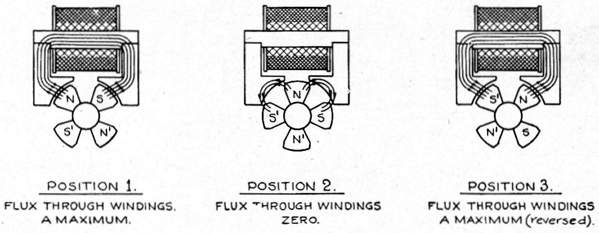
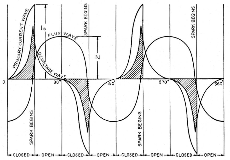
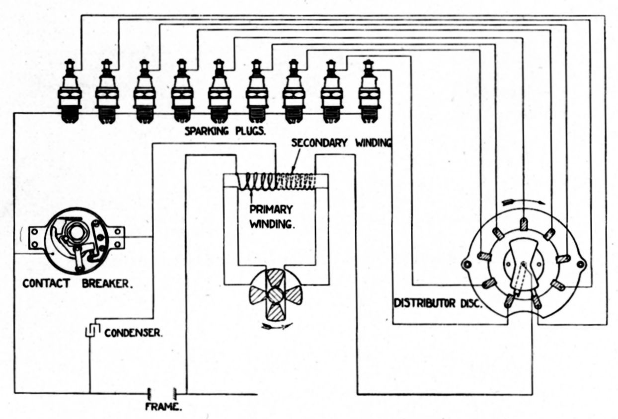
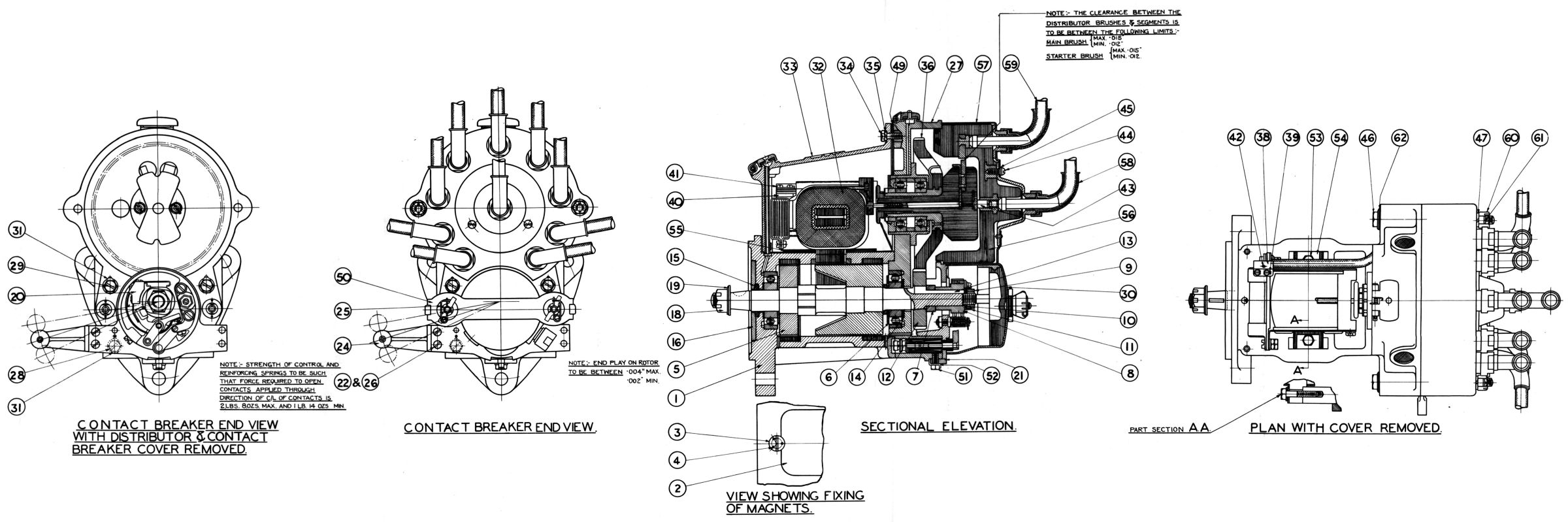
| Magnetic Flux Reversal in Armature Core | Flux and Voltage Curves | Ignition System Diagram | Magneto |
The British Thomson-Houston (BTH) SC.9-5B magneto belongrf to aclass of high-tension polar inductor magnetod that were specially developed to meet the requirements of aeroplane engine ignition in regard to absolute reliability and endurance.
The magneto featured a stationary armature in which the current that produced the spark was generated. This current reached a maximum value four times during each revolution of the rotating polar inductor and accordingly four sparks per magneto shaft revolution were produced. The basic operating principle of all electrical ignition apparatus was electro-magnetic induction, which was the generation of a current through varying magnetic lines of force. In the case of a magneto, the magnetic lines of force were provided by the magnets fitted to its housing. These lines of force were rapidly changed in the armature, which produced the high tension current, by means of the polar inductor.
Description and Operation. Two very strong cobalt steel magnets were fitted on the sides of the main body casting and in intimate contact with two laminated annular poles at each end of the body casting. The magnet poles were disposed axially so that the two laminated poles at the ends of the body casting were of opposite magnetic polarity. Magnetic flux entered the rotating inductors annular end via a small air gap and passed through the inductors to the armature core. Inductor rotation produced the magnetic flux reversal in the armature core as illustrated in Figure 69. There were four complete armature core flux reversals for every revolution of the rotor shaft. Figure 70 shows flux and voltage curves produced. The primary winding was connected to the armature core at one end and the other end was connected to the the secondary winding and to the contact breaker. A cam operated the the contacts four times per shaft revolution. When the contacts were closed the primary winding was short-circuited and as the inductor rotated, the current induced in the primary winding built up until the cam separated the contacts at the instant when this current was at a maximum. The instantaneous collapse and reversal of the flux at the moment of the contact break produced a high voltage in the secondary winding, which caused the spark. The other end of the secondary winding was connected to the small brass insert in the armature coil moulding. This insert made contact with the collector brush, which was in turn connected to the rotating metal brush. The spark leapt from the rotating brush to the various segments as the brush rotated and thus the ignition sparks were distributed to the various spark plugs on the engine. Figure 71 depicts a diagrammatic sketch of these connections. The safety spark gap was one of the special design features of this type of magneto. Should any connecting lead become disconnected from its plug, undue rise of voltage, which might damage the magneto insulation was guarded against by the provision of the safety gap across which the spark may discharge when there was no alternative gap between the spark plug electrodes. A brass point protruded from the distributor brush box toward the slow speed-gear-wheel and the earth side of the safety gap was fixed to the gearwheel. Owing to the fact that this gap was always rotating, the air between the electrodes was in a constant turbulent state; thus ionization was reduced to a minimum. Furthermore, the magnetos were vented so that the air was constantly being changed. These features ensured that the safety gap was stable in practice.
It was necessary to close and open the primary circuit four times during each rotor shaft revolution, and this was effected by means of a four-lobe cam that was mounted on the shaft end. This cam operated a bell-crank lever, the end of which carried the movable contact. When the lever was deflected by the cam the distance between the platinum points were not be greater than 0.012", a value that was to be checked from time to time, and adjusted if necessary.
The design of these magnetos was such that the various screws and the different components, which were grouped to form distinctive sub-assemblies, were readily accessible. The magneto was fitted with a straight-through steel shaft on which the rotating inductors were mounted, forming an excellent mechanical construction specially adapted to withstand the severe vibration met with in aeroplane engine service. The rotor required no fixing screws. Since the windings did not rotate, no slip ring were required, and the leakage surfaces were appreciably in excess of those provided in rotating armature magnetos. These two features ensured immunity from internal electrical leakage. The entire iron circuit, in which the flux reversal occured, was laminated, thus giving a very rapid rise of voltage when the contacts opened and resulting in increased spark intensity. A special distributor operated with a small spark gap between the rotating metal brush and the segments, the latter being arranged to protrude well beyond the material surface. With distributors of this design carbon tracking did not occur. The magnetos were designed for use with metal braided shielded wire, but by the introduction of special fittings, plain rubber covered wires could also be used.
Claudel Hobson A.V.T. 80.B Carburettor
These carburettors were designed to operate on high-efficiency aero engines. They were completely pressure balanced, and the mixture control range for altitude was enough to meet all requirements up to any height. The demand for a great mixture control range called for a special mixture control system that avoided any rapid action and ensured that equal mixture control lever movement increments gave equal and progressive mixture weakening. It was also essential for operating convenience that for a given mixture control lever position the mixture was weakened by the same percentage at all throttle positions. The pilot then only had to alter the mixture control lever position with change of altitude, not for different throttle positions at the same altitude. Because of mixture control requirements at great heights it was imperative that the mixture control valve was interlocked with the throttle so that it was closed for a dive, thus ensuring the engine would open up again. On engines likely to cruise at altitude and part throttle for long periods, fuel economy dictated that the interlocking gear did not begin closing the mixture control before the half-throttle position.
The carburettor was of the diffuser type, using a progressively emptied well with air bleed and the power jet principle employed fulfilled the fundamental requirement of maximum power at full throttle with economical running at part throttle.
The butterfly throttle now used was quite new in principle and was not only the throttle, but also part of the slow running system. A float gear design gave great capacity with a given size of float chamber. A special form of choke (venturi) preventing freezing in the carburettor. Supercharged engines were controlled automatically by an automatic throttle control, which prevented the engine from developing power in excess of normal boost at low altitude, but also provided more boost for takeoff. In order that this extra power was developed safely, an extra mixture enrichment jet prevented detonation and enabled the takeoff boost to be safely carried during the takeoff period. An accelerator pump enabled good acceleration to be obtained with a main jet set for economical cruising. Diagrammatic Description
 |
 |
 |
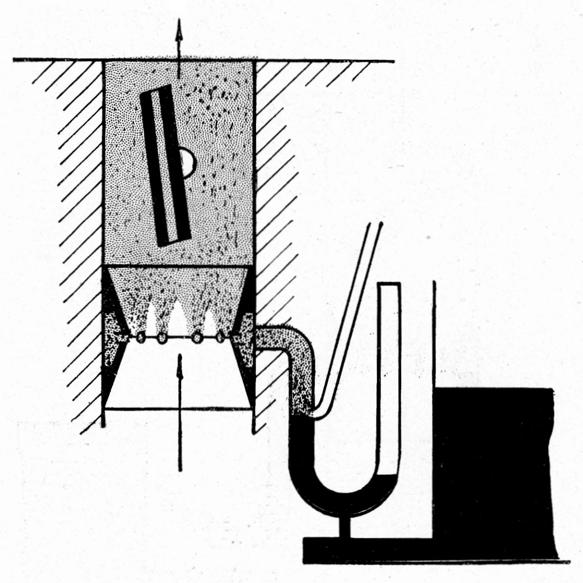 |
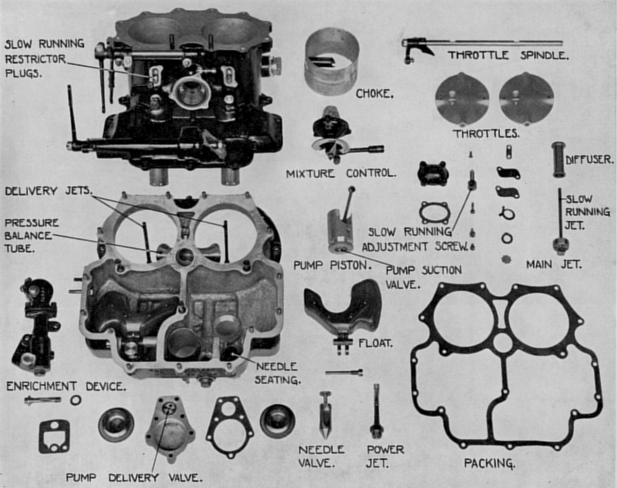
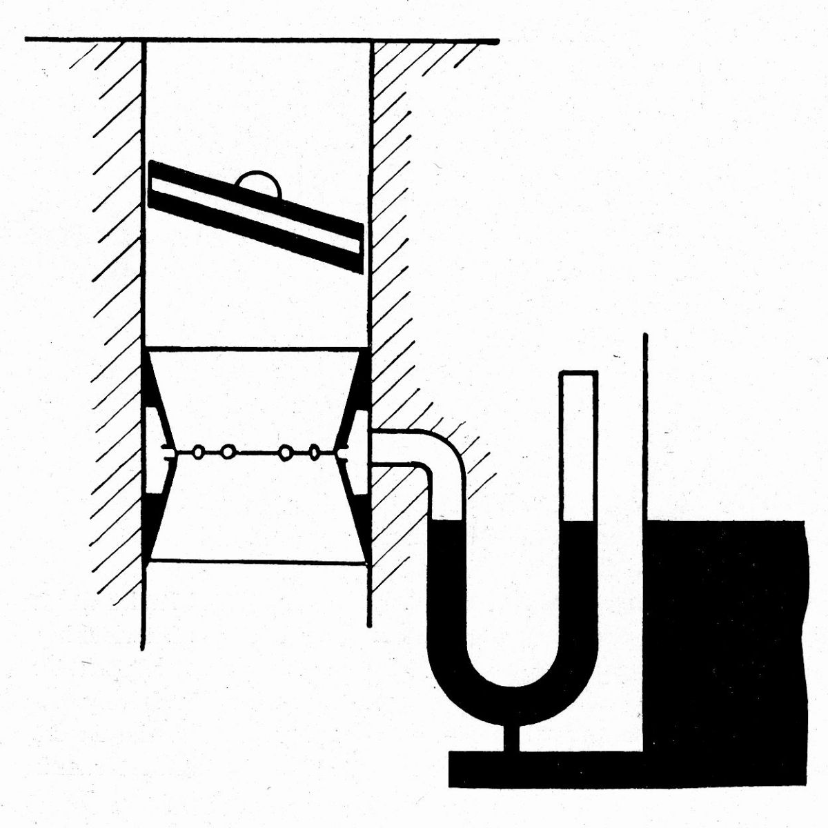
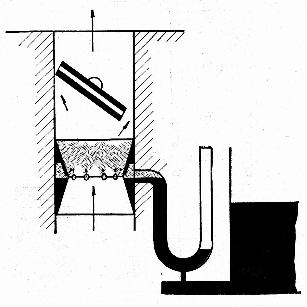
| A.V.T. 80.B Parts | Fig. 75. Off | Fig. 76. Part-Throttle | Fig. 77. Wide Open |
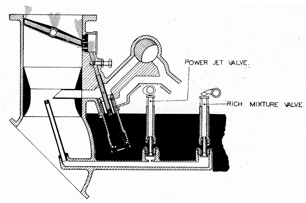
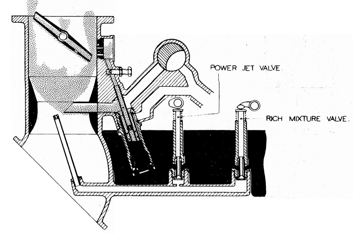
A U-tube (Fig. 75) was filled with fuel by through a jet up to a constant level maintained by the float chamber. The throttle was closed, the pressure on the U-tube exit was atmospheric and balanced by the air pressure on the other limb of the U-tube, rendering the fuel at equal heights in both U-tube limbs. Figure 76 shows the throttle partly open and air passing through the choke; consequently choke pressure was lower than atmospheric, while the U-tube free end remained at atmospheric pressure, driving the fuel in the U-tube into the choke tube. This operation of the U-tube by pressure difference was generally called suction. The fuel would have poured into the choke entirely unatomized except that the admission of diffuser air broke up and atomized the fuel before it got into the choke. Figure 77 shows a pipe supplying air below the ordinary U-tube fuel level. Air was driven in and mixed with the fuel as shown.
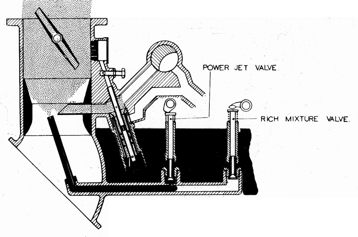
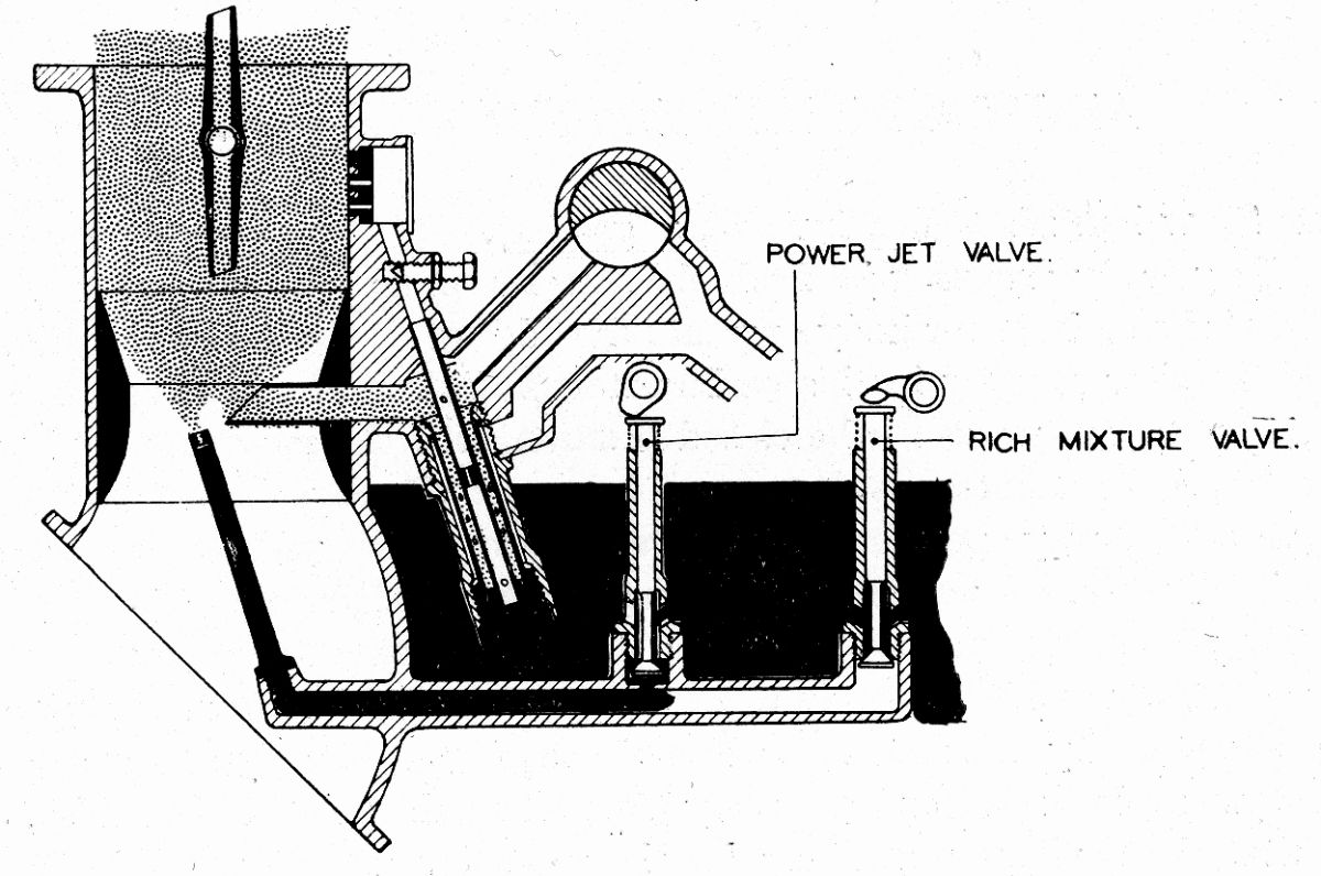
The A.V.T.80 carburettor was arranged to conform with the schemes shown Figures 78, 79, 80 and 81, but in some cases the choke tube was of the type that had the tube in the choke covered by a streamlined shroud, and in others the tube type. In Figure 78 when the carburettor was in the slow-running or idling conditions, the diffuser was inoperative and fuel flowed from the slow-running jet and was then mixed with air from holes in slow running tube. It was then ejected beside the throttle, and via the transverse passage into the center and other side of the carburettor uptake. In Figure 79 the throttle was slightly more open, the slow running and transverse tubes were still functioning and the diffuser was beginning to act. The first row of depression holes were uncovered, and air was proceeding via these holes to mix with the fuel and form an emulsion. In Figure 80 the condition was full power; the slow-running and transverse passages were out of action while the diffuser was in full action; all depression holes were uncovered and taking air to mix with the fuel. In addition, the power jet valve had opened and was adding fuel to that supplied by the main jet, in order to convert the economical cruising mixture given via the diffuser to the richer mixture necessary for maximum power.
 |
 |
 |
 |
 |
 |
| Fig. 78. Slow Running | Fig. 79. Throttle Cracked | Fig. 80. Full Throttle | Fig. 81. Takeoff, Rich Mixture |
Fig. 82. Mixture Control Operation |
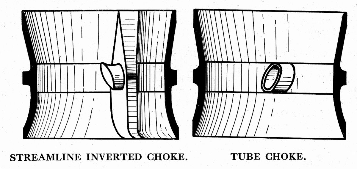
Fig. 83. Choke Tubes |
In Figure 81 the carburettor was in takeoff condition where it was assumed that the automatic throttle control override was in action and the rich mixture jet was adding its quota to the normal fuel supply, normally a 10 – 15% addition. In Figure 82 the carburettor was still in full power condition, but the mixture control cock and connecting passage are shown. Air admitted through the mixture control cock into the emulsion passage weaked the suction on the jets in proportion to the air admitted through the cock.
Figure 83 shows two types of choke tubes, the streamline inverted tube, and the plain tube.
Carburettor Adjustment
The idling or slow-running jet fed the slow-running mixture to a hole situated in the carburettor body side opposite the butterfly throttle edge. This carburettor used a passage situated in the throttle that registered in the closed position with the slow running hole. The mixture was drawn not only past the throttle plate edge when it was slightly open, but also through the transverse hole in the throttle. A portion of the mixture emerges from the throttle adjacent to the other side of the carburettor bore. There was a small hole in the center of the throttle through which emerged a further portion of the slow running mixture. By this means the mixture was not fed entirely to one side of the induction system, but more or less evenly throughout the whole area. Also, due to the fact that the depression increased on the transverse hole throughout the early part of the throttle movement, a flat spot in throttle response was obviated. Slow-running mixture adjustment was accomplished by changing the jet and turning the adjustment screw. At small throttle opening diffuser and choke tube action caused the mixture to be drawn through the emulsion passage in the carburettor body and into the choke tube; the main jet size controlled this quantity. The Claudel-Hobson full-throttle power jet supplied a small amount of fuel at full throttle only. This allowed the mixture strength throughout the smaller throttle openings to be economical while maximum power was still obtained at full throttle. These power jets were flow calibrated, and their numbers represented the cubic centimeters of fuel that they pass on a recognized standard measuring instrument. In supercharged engines full power was obtained at less than full throttle. The power jet valve was then set to open at the full-power at ground level throttle position. The power jet cam was operated by the pump shaft and lever with its vernier adjustment timed power jet operation. The manual mixture control system for altitude did not affect the carburettor's automatic features, which remained constant, whatever the amount of control given, within the limits of mixture strength on which it was possible to run the engine. Claudel-Hobson used a conventional float mechanism with a needle valve, but a float with much-increased leverage resisted a greater fuel head than other types and flooding was unlikely under normal circumstances.
Send mail to
![]() with questions or comments about this web site.
with questions or comments about this web site.
![]()