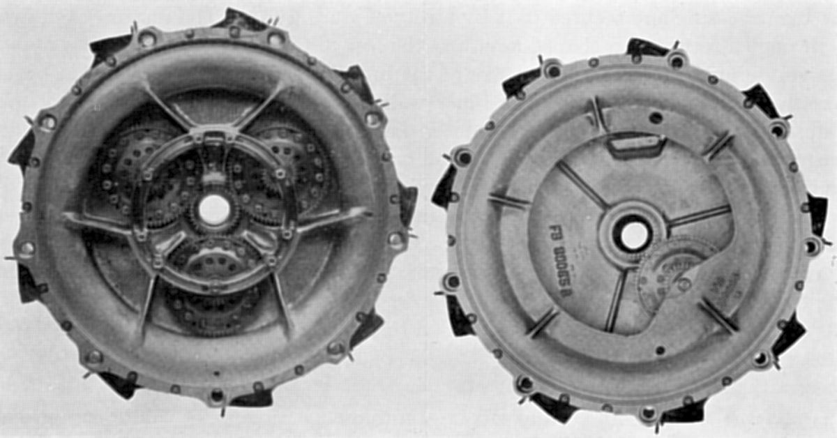
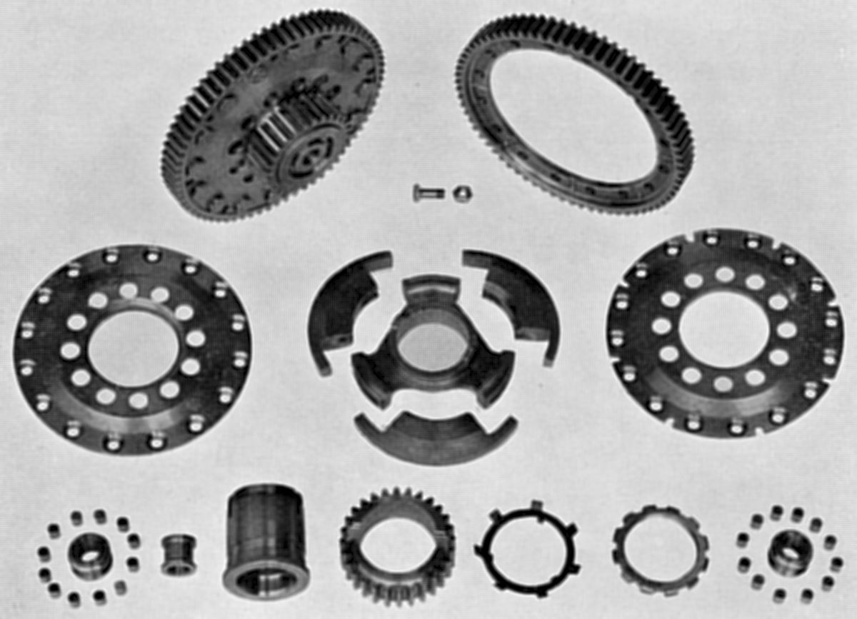
Left, Pegasus II-M, 3-Pinion
Right, Pegasus II-L, 1-Pinion
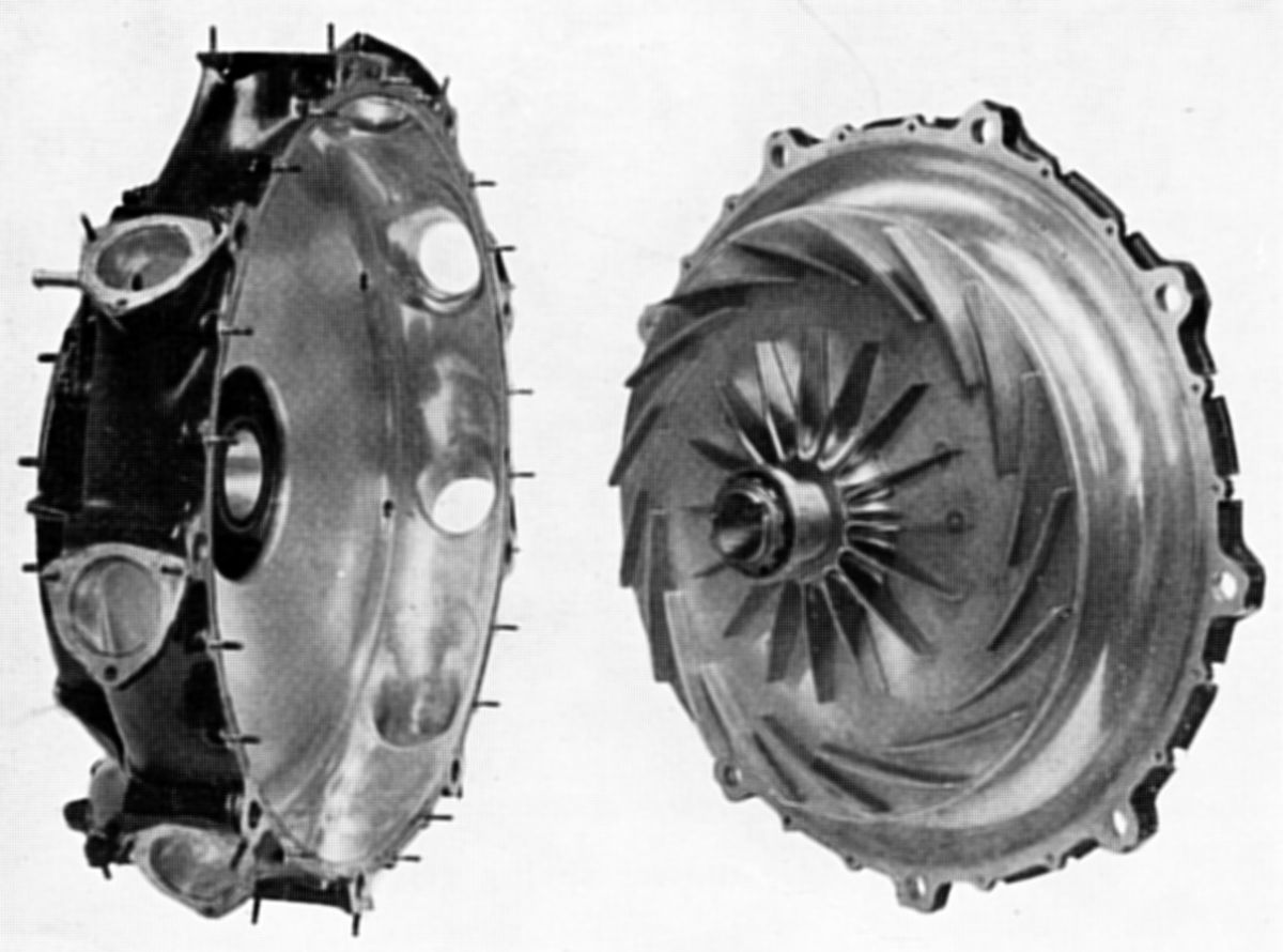
Blower Casing,
Impeller, Involute
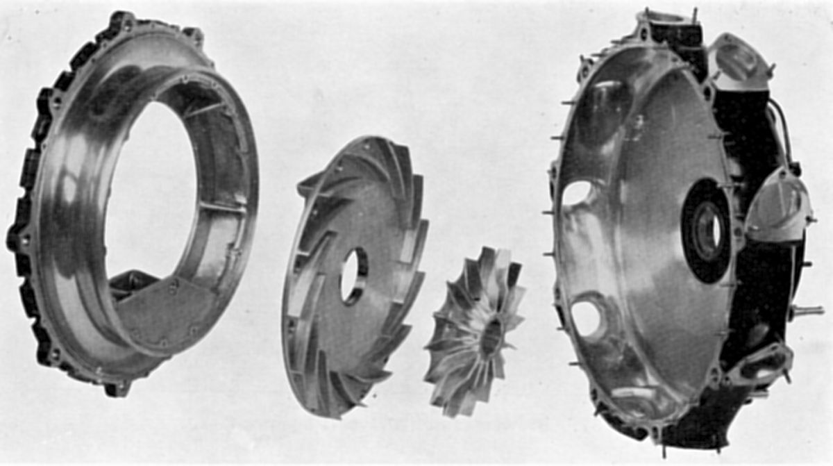
Vane Disc, Shrouded Impeller,
Volute Casing
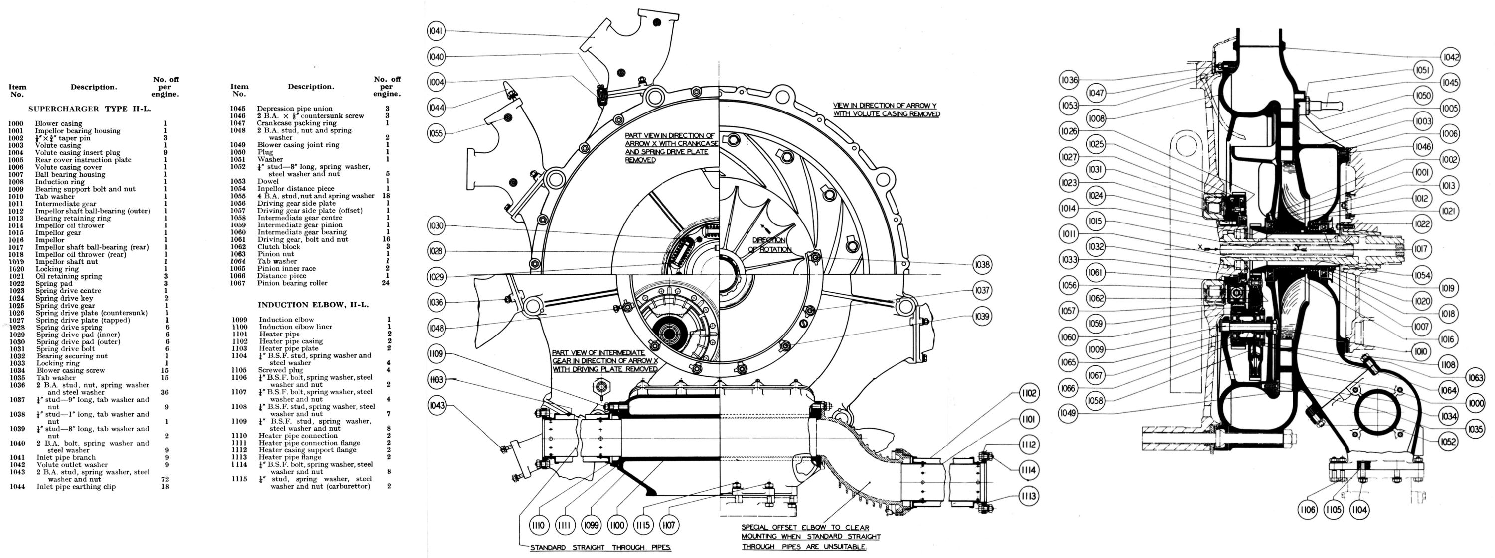
Bristol Pegasus II.L and II.M
Supercharger, Lubrication
Compiled by Kimble D. McCutcheon
Published 06 Feb 2025
| Part 1: Specifications | Part 2: Description |
| Part 3: Supercharger, Lubrication | Part 4: Accessories |
| Part 5: Magnetos | Part 6: Carburettor |
| Part 7: Automatic Throttle Control | Part 8: Starter |
Supercharger
Both the Pegasus II-L and II-M used gear driven centrifugal superchargers located in the induction system between the carburettor and the engine, thereby taking advantage of the blower rotation to provide a homogeneous and even mixture distribution. The mixture from the carburettor was admitted (via an exhaust-heated elbow in the II-L engine) to a cast light alloy volute, from where it was delivered by the impeller, which rotated concentrically around the crankshaft, through the vaned diffuser to the annular induction chamber of approximately circular section. From this chamber the mixture flowed through nine tangential outlets, each of which supplied two inlet pipes of adjacent cylinders.
|
|
|
|
|
| Blower Drives Left, Pegasus II-M, 3-Pinion Right, Pegasus II-L, 1-Pinion |
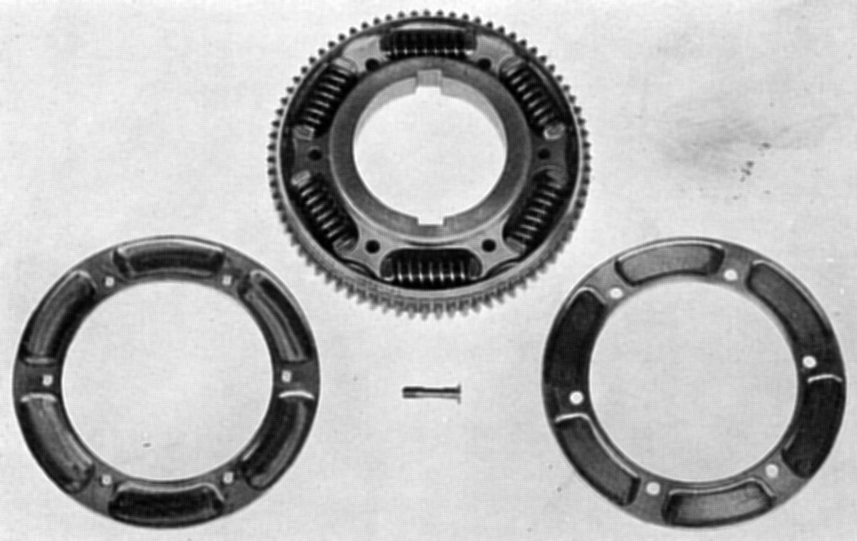
Blower Spring Drive | Pegasus II-M Blower Casing, Impeller, Involute |
Pegasus II-L Induction Ring, Vane Disc, Shrouded Impeller, Volute Casing |
Blower Clutch Drive |
 |
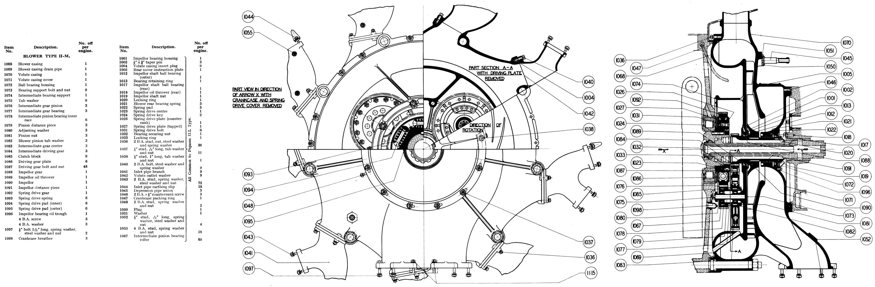 |
| Pegasus II-L Supercharger | Pegasus II-M Supercharger |
The geared blower drive was supplied in various ratios according to the degree of supercharge required. For the II-M type a ratio of 7.0:1 was employed, while the II-L type (a lower duty blower) used a 5.7:1 ratio. At the 2,300 rpm maximum engine speed, impeller speeds were 16,000 and 13,000 rpm respectively. The kinetic energy imparted by the blower was considerable and any attempt to rapidly change its speed such as a sudden opening or closing of the throttle (or even the cyclic crankshaft fluctuations) would impose high loading upon the transmission. A flexible spring drive was therefore incorporated that damps out cyclic variations and a system of slipping clutches that limits the torque transmitted and allows slip in the case of rapid acceleration. The clutches were actuated by centrifugal force and hence did not come into operation until a certain predetermined engine speed was reached.
Chief Differences between the II-M and the II-L Types
Aside from the blower gear ratio, the II-M type used three sets of clutches instead of one as on the II-L type. This necessitated a different blower casing construction for the single pinion drive with the intermediate gear supported between two casing side walls, whereas in the three-pinion type a steel supporting ring was used. The II-L the blower casing was split so that the diffuser and casing main wall formed separate parts. The type II-M impeller was steel while the II-L used light alloy, which, along with a larger boss, necessitated several minor alterations to the adjacent components. The volute casing was also different with the II-L type accepting a heater elbow.
Pegasus II-M Blower (7.0:1 Ratio)
The cast light alloy Volute Casing was spigoted to the blower casing and secured to it by a ring of studs. The mixture was drawn in through a rectangular mouth at thecasing rear and continued round the volute until it reaches the impeller center, which was rotating in the same direction as the crankshaft. The volute inner wall formed one side of the diffuser chamber, while around the outer diameter were nine equally spaced elbows tangentially inclined so that an efficient gas outlet was obtained. Branch pipes were attached to the outlets, each branch supplying the two inlet pipes of adjacent cylinders. The volute rear casing was closed by a magnesium cover spigoted to the main body and attached by a ring of countersunk screws. Its central boss carried the impeller rear bearing housing, which was a press fit in the cover. The ball bearing was an easy fit in the housing, and three light coil springs located in the cover provided a slight end load to the outer race. This initial loading ensured that the balls did not skid in their races during acceleration.
Interposed between the volute casing and the rear half crankcase was a cast aluminum alloy Blower Casing. It was spigoted to the crankcase and was secured by extensions of the nine crankcase bolts, which also passed through the volute casing; the joint included a rubber sealing ring. The blower casing outer diameter was of semi-circular section, which when bolted to the volute casing gave an almost circular-sectioned annular induction chamber. Integral with the main wall and facing rearwards were the curved diffuser vanes, which formed diverging gas passages. The casing main wall supported the front impeller bearing housing, which was retained by a circlip. The housing itself was pressed into and pinned to the blower casing. On the front of the main wall were three equally spaced brackets that carried at their forward end a steel support ring for steadying the intermediate gear bearing support bolts.
The case-hardened Blower Spring Drive center was mounted on the crankshaft rear half immediately behind the main bearing, driven through two keys and retained on the shaft by a bronze nut and tab washer; an internal thread at the rear end was provided for withdrawal. The torque was taken through six short stiff springs located on pairs of pads interposed between the driving members of the center and gear. The center's driving dogs were slotted transversely to receive the corresponding dogs of the spring drive gear. The steel pads were case-hardened and were so arranged that the shank of one was a sliding fit in the hollow stem of the other. The springs and pads were located between aluminium-bronze side plates, which were bolted to the spring drive center. The gear droves three sets of intermediate gear pinions and provided the first train in the two-stage gearing. The intermediate gear included a centrifugal friction clutch that also ensured equal distribution of the drive in the three intermediate gear sets. These intermediate gears and clutches were similar and were built up as described below.
Clutch Drive. The intermediate gear pinion was mounted on and located against a shoulder at the intermediate gear bearing forward end. It drove intermediate gear center through two dogs on its rear face. The two parts, which were a light tapping fit on the bearing sleeve, were retained by a nut and tab washer. The sleeve ran on two sets of rollers, the inner races of which were mounted on the support bolt. Nine bolts were used, three for the bearings and six for securing the support ring to the blower casing. The rear inner race registered against a shoulder on the blower casing and was separated from the front race by a distance piece, while a steel adjusting washer was interposed between the front race and the support ring. The washer thickness was determined on assembly and was numbered so that it could be replaced in its correct position after any subsequent disassembly. The support bolt head was milled to prevent turning when finally pressed into the casing. The intermediate gear center, which was driven by the intermediate pinion, had three equally spaced driving members radiating from its center; these located the phosphor-bronze clutch blocks. These blocks, which were free to find their own position radially, were of a wedge or vee section, the sides of the vee being frictional faces by which the drive was transmitted. The clutches were imprisoned by two steel side plates locating on the clutch center boss and secured to the intermediate gear internal flange by a ring of bolts. The intermediate gears drove the impeller gear and provide the second and final stage in the gearing, giving a total ratio of 7.0:1.
Impeller. The impeller gear, to which the impeller was attached, was mounted on two bearings and ran concentrically with, and in the same direction as, the crankshaft tail piece. As already mentioned, the front bearing was housed in the blower casing main wall with an oil thrower interposed between it and a shoulder on the impeller gear. Immediately behind the bearing was the impeller, splined to the impeller gear. Made from nickel chrome steel, it had sixteen radial blades, the front edges of which were perpendicular while the rear edges tapered toward the tip. Captured between the impeller and the rear bearing was an oil retaining sleeve with a left hand return thread, while at the bearing rear was an oil thrower. The complete assembly was secured to the impeller gear by a bronze nut and tab washer.
An oil priming pipe with an external nipple was fitted to the crankcase. Oil was injected after a rebuild or long idle period and found its way through two holes drilled at the blower root of the casing upper support web and lubricated the front impeller bearing. As already mentioned there was also a nipple on the rear cover connected to a drilled passage in the cover and used for priming the rear blower bearing. The intermediate gear pinions were lubricated by oil spray from the crankcase through three nozzles screwed into the crankcase rear wall. A tube screwed into the blower casing bottom drained the oil back into the crankcase chamber.
Pegasus II-L Blower (5.7:1 Ratio)
The II-l volute casing was very similar to the I1-M, but the volute entry was considerably shortened to accommodate a heated induction elbow. The blower casing consisted of the casing proper, with its diffuser vane disc and forming the partition between the induction chamber and blower gearing, and the induction ring to which it was spigoted and bolted using a rubber sealing ring in its outer edge. The induction ring formed the induction annulus inner half. Integral with it and in the lower half two supporting walls carried the intermediate bearing spindle.
The Spring Drive was of the same construction as the II-M, except that the II-L had 75 teeth versus the 11-M's 79. The springs were less stiff and the spring pad shanks were slightly smaller in diameter.
The Clutch Drive design was to the 11-M, but had only one set of clutches and intermediate gears instead of three. The intermediate gear pinion, driven by the spring drive gear, had 28 teeth and was mounted toward the intermediate gear bearing front end. Two sets of rollers were employed as on the II-M type; however there was no adjusting washer. The intermediate gear center had three driving members, which were offset and located the clutch blocks. The blocks were specially formed to provide the mass necessary for the lower-speed single clutch unit. The intermediate gear and the impeller gear both had the same number of teeth as in the 7.0:1 gear. The impeller gear was slightly different, however, in that longer splines were provided to suit the wider impeller boss , which in this case was made from a light alloy. The front and rear impeller bearings were the same in both types but the oil return sleeve was shorter and had a lip at its forward end. The boss on the volute casing cover was shorter to accommodate the wider impeller boss. The three crankcase wall lubricating nozzles were not required on the low duty blower. Holes in the induction ring drained the gear chamber instead of the pipe through the blower casing as in the case of the II-M type.
Blower Gear Train. The II-M type spring drive gear had 79 teeth and drove the intermediate pinion with 24 teeth, giving an increase of 79/24 = 3.2917. The intermediate gear with 70 teeth had the same speed as the pinion and drove the impeller gear with 33 teethm giving a further increase of 70/33 = 2.1212. A final ratio of 6.9823:1 was therefore obtained. The II-L spring drive gear had 75 teeth driving the intermediate pinion with 28 teeth giving the first stage of 75/28 = 2.6786. The intermediate gear with 70 teeth drove the impeller gear with 33 teeth giving the second stage of 70/33 = 2.1212. The final ratio being 5.6818:1.
The Induction Heater Elbow, was an aluminium alloy casting secured to the volute casing mouth by twelve studs, seven of which were fitted to the elbow itself, while the remaining five were fitted to the volute casing flange facing. The carburettor was secured to the elbow by a twelve-boss flange suitably drilled for studs and bolts. Four studs, screwed into the induction elbow, two studs screwed into the carburettor body flange, and the remaining six bosses were drilled for bolts. Mixture from the carburettor passed through the elbow around an internal cylindrical chamber running the full length of the elbow. A steel liner was shrunk into the chamber bore to eliminate the possibility of exhaust gases burning through the aluminium casting. Spherical seats were formed at each end of the gas chamber to accommodate the heater pipes.
Lubrication
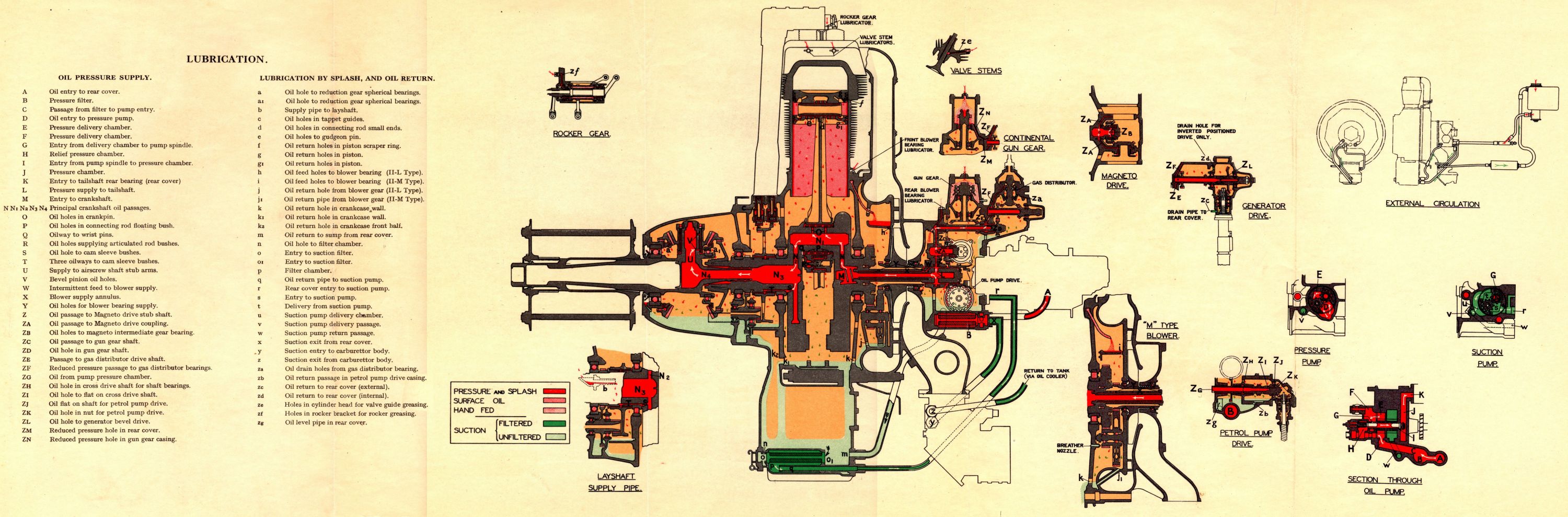 |
| Pegasus Lubrication System |
The lubrication system delivered oil under pressure to the master rod big end, the articulated rod pins, cam sleeve bushes, reduction gear, impeller gear, magneto drive, gun gear drive (continental type), gas distributor drive, fuel pump flexible drive and electrical generator flexible drive. Indirect or splash lubrication was provided by oil draining from the above lubricated pistons and small ends, crankshaft main bearings, cam gear and tappets, reduction gear parts, blower gear and rear cover gears.
The rocker bearings and valve guides were greased by hand. Priming nipples were also provided at suitable points so that after long standing periods, vital points could be lubricated before the main circulation was flowing.
Oil flowed from the tank through a filter in thee oil pressure pump rear cover from where it circulated round the engine. The oil then drained into the sump and was filtered before being drawn up by the suction pump from where it returned to the tank via the carburettor body and an oil cooler if fitted.
Circulation in the Pump. Oil from the tank was fed into the rear cover where it passes through a filter before reaching the oil pump. Pressure oil from the pump passes into the outer end of the hollow driven gear spindle; the pressure was regulated by the relief valve, the surplus oil being diverted back into the pressure pump again. The oil flowed from the driven spindle through the lightly-loaded check valve to a chamber formed between the pump unit end and the rear cover inner wall from where it was delivered through drilled passages to the tail shaft rear bearing, which was virtually the starting point of oil circulation in the engine. The suction oil was drawn from the sump through an external pipe to a port in the rear cover, through drilled passages in the cover to the exit situated beneath the suction inlet.
Circulation in the Engine. Oil entered an annular groove in the tail shaft bearing housing and flowed to a similar groove in the rear bearing through a port in the bearing bronze shell. Two diametrically opposite holes in the tail shaft lined up with the annulus, thus maintaining a steady flow through the crankshaft center . A drilled passage conducted the oil to the hollow crankpin, where two small holes fed the crankpin flat and supplied the master rod big end. Oil from the connecting rod floating bush front end was received by an oil retainer bolted to the master rod big end, and this fed the oil (under pressure from the main system) to each articulated rod pin from where it reached two flats on the pins and lubricated the bushes. Oil thrown from the big end lubricated the cylinder walls, pistons and gudgeon pins by splash.
Oil in the crankshaft passed down the passage drilled in the crank front web to the shaft front end. The hole in the web continued across the shaft center line and fed a duct drilled through the web face, which in turn supplied an annulus formed by the chamfer in the bearing inner race bore and the radius on the shaft. Three broad but shallow oil ways on the shaft communicated with this annulus, supplying oil to a wide groove in the crankshaft sleeve bore; the groove was terminated on either side of the keyway so that undue leakage was obviated. Holes in the crankshaft sleeve supplied the cam sleeve bushes. The tappets, rollers, etc., were splash lubricated by oil thrown from the ends of the cam sleeve bushes and from the cam sleeve. Sleeves fitted to the lower tappets prevented over-oiling these parts. The cam sleeve lobes dipped in an oil bath formed in the tappet guide locating ring bottom. Oil from the reduction gear, caught in a tray on the front cover and delivered through a pipe, lubricated the layshaft bearing.
Oil from the shaft front end passed into the airscrew shaft rear end, lubricating the tail bearing and then passed through drilled holes in the stub arms to the bevel pinion floating bushes. An oil bath in the reduction gear casing had its level maintained by an overflow pipe fitted to the front cover wall. The airscrew shaft stub arms dipping in the oil bath was sufficient to lubricate the gears and to provide sufficient splash for the reduction gear bearings. An oil retainer at the airscrew shaft front terminates the oiling at the engine front. The oil was returned to the sump through suitably drilled holes in the crankcase.
Rear Cover and Auxiliaries. A short oil way in the tail shaft rear bearing bush bore delivered oil once every engine revolution to an obliquely drilled hole in the tail shaft, which in turn supplied the annulus formed by the insertion of a tube in the tail shaft as explained in the crankshaft section. A hole at each end of the tail shaft supplied oil from this chamber to the impeller rear bearing, and also to the impeller gear. In the II-M type, additional oiling to the blower gears was provided by the crankcase wall nozzles already mentioned. A pipe inserted across the blower casing to the crankcase (in the II-M type) or a hole drilled in the induction ring (in the II-L type) drained oil from the blower gear.
The rear cover and the rear cover drive component lubrication also started at the tail shaft rear bearing. From the annulus in the bearing housing a vertically-drilled passage in the rear cover delivered oil to the hollow magneto intermediate gear stub, from where it lubricated the magneto drive assembly rear end. Two horizontally-drilled holes on each side of the stub shaft fed the magneto coupling bearings. Continuing above the stub shaft, the vertical hole reached the gun gear shaft forward end, which was hollow; the oil was forced through it to the rear end where it found its way through the bush to a drilled passage in the distributor drive casing and supplied the distributor drive shaft forward end. Oil from this bearing was forced under greatly reduced pressure through an obliquely drilled hole to the distributor spindle bearings; the supply volume was controlled by the bearing clearance.
If the continental gun gear was fitted, a reduced pressure oil feed was taken from the gas distributor drive shaft casing end, through the rear cover to an almost vertical hole in the gun drive casing, from which oil found its way to the driven gear wheels. Surplus oil drained back into the rear cover through the shaft bearings.
The hollow cross drive shaft was fed directly from the oil pump chamber and was drilled at various places along its length to provide oil for the shaft bearings, and fuel pump drive (when required). When a fuel pump was used, oil from a flat on the shaft escaped through a specially drilled nut and lubricated the bevel gears at reduced pressure. The oil returned by way of a channel cut in the pump drive casing. The tachometer gears and shaft were lubricated by oil thrown from the auxiliary drive shaft bearings. An oil pipe in the rear cover maintained a level for the auxiliary drive shaft gear.
Electric Generator Flexible Drive. When the generator flexible drive was fitted, oil was forced along the distributor drive shaft through a hole between the ball race and the bevel gear, lubricating the bevel gears. Oil return was installation specific as explained in the Electric Generator Flexible Drive section. The flexible casing was packed with a mixture of graphite and grease every 100 hours. Bulkhead type bevel gears were lubricated in the same manner as the flexible drive, but the couplings and universal shaft ran dry.
The Rocker Bearings were greased as were the valve guides. A single nipple at the rocker bracket rear supplied the rocker assembly, while individual nipples on the top cylinder head fin fed the valve guides.
Priming nozzles on the crankcase and rear cover initially lubricated the blower bearings, while a nipple on the gun casing cover supplied grease to the gun cam tracks.
Send mail to
![]() with questions or comments about this web site.
with questions or comments about this web site.
![]()