Bristol Pegasus II.L and II.M
Description
Compiled by Kimble D. McCutcheon
Published 2 Feb 2025
| Part 1: Specifications | Part 2: Description |
| Part 3: Supercharger, Lubrication | Part 4: Accessories |
| Part 5: Magnetos | Part 6: Carburettor |
| Part 7: Automatic Throttle Control | Part 8: Starter |
|
|
| Crankcase, Front Cover, Oil Sump | |
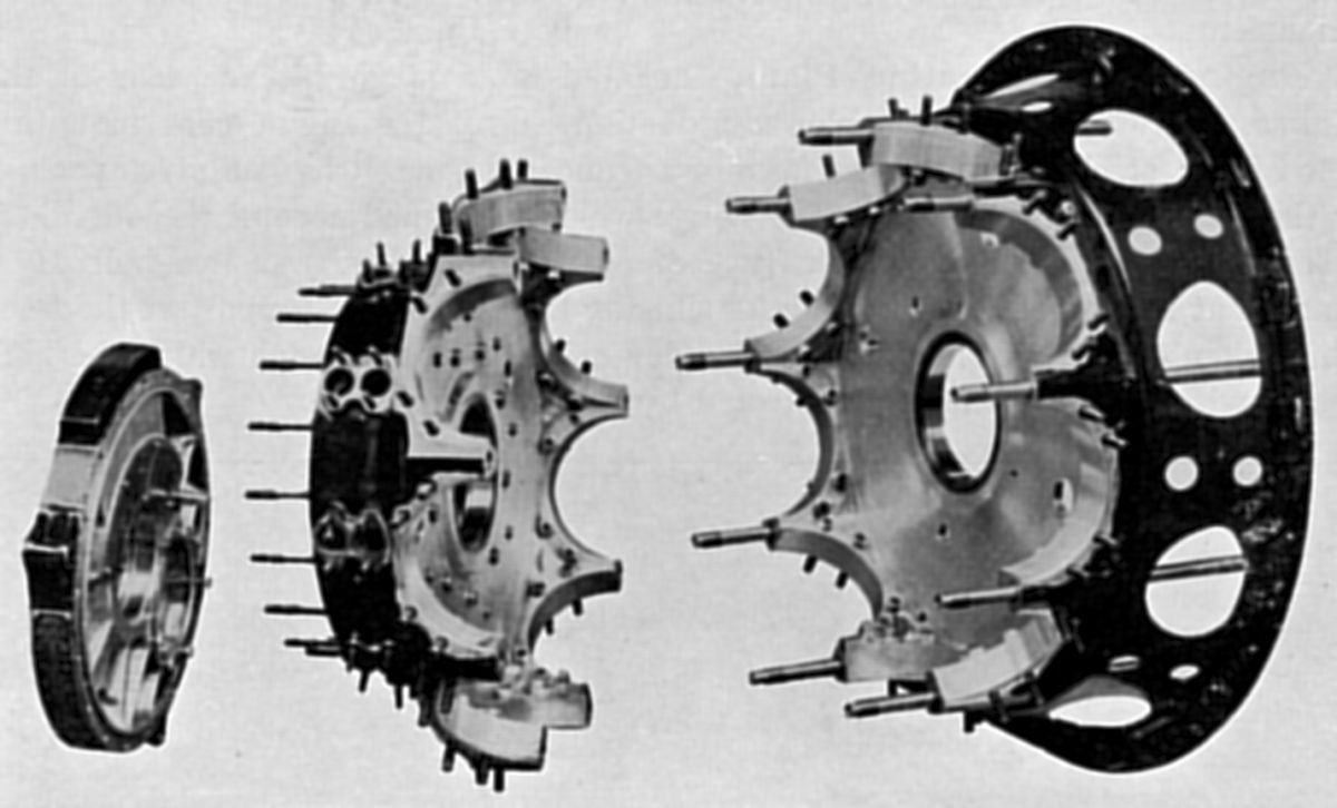
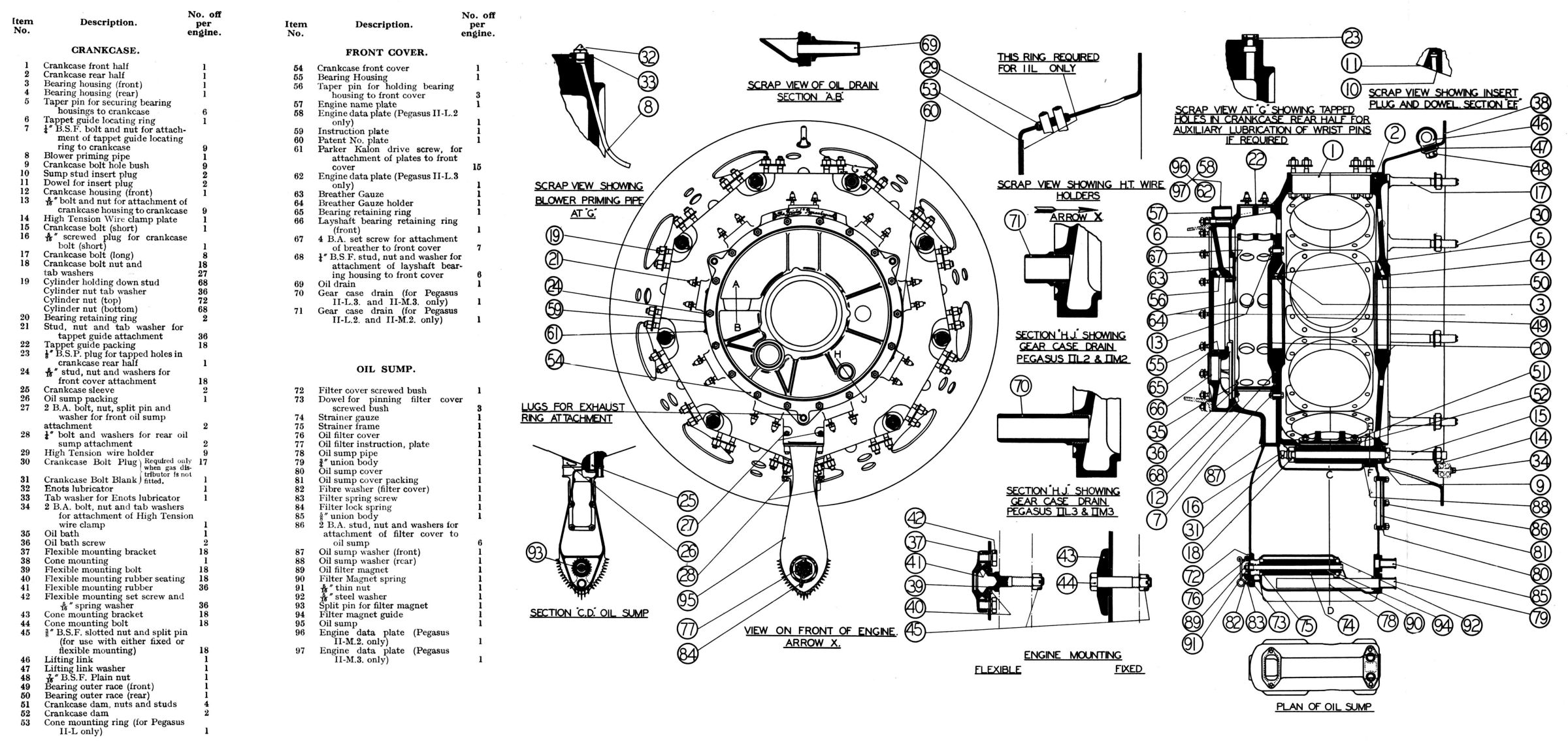
The Crankcase consisted of front and rear halves, both aluminum alloy drop forgings that were bolted together and machined all over. The two halves were split on the cylinder center lines and were assembled using nine close-tolerance crankcase bolts; the bolt nearest the sump was shorter at the rear end than the others. There were nine machined faces radially disposed around the crankshaft center line that were also bored to receive the nine cylinder spigots and hold-down flanges, each of which was secured by eight hold-down studs. Shrunk into the crankcase front-half main wall and secured to it by nine bolts was an aluminium alloy housing that carried the crankshaft bearing outer race, which was shrunk and pinned by three taper pins into an aluminium bronze housing. The crankcase rear-half bearing housing was carried directly in the crankcase wall. A tappet guide locating ring was bolted to the front crankcase half. Bolted to the crankcase inside between No. 5 and 6 cylinders was an oil dam that prevented excess oil from surging into the lower cylinders. A machined passage allowed oil to drain into the sump in the usual way.
A Front Cover was attached to the crankcase front half by eighteen studs and located by a spigot in the front cover. This was an aluminium alloy casting to which the crankshaft front thrust bearing race housing was affixed. At the front cover top was the engine breather, an aperture facing away from the airscrew and connecting up to a passage leading out from the engine center and guarded at its inner end by a brass gauze. The cam gear layshaft front end was also supported in the front cover. Two oil drains were provided, one just above the engine center line and the other according to which reduction gear was fitted. Equally spaced around the periphery were three lugs for the exhaust ring attachment.
The Engine Cone Mounting Plate was located on a spigot between the crankcase rear and the blower induction ring. A steel pressing formed a truncated cone with suitable openings for the induction pipe elbows. The flange that was formed around the outside was drilled to take a fixed or flexible type of engine mounting. An eye bolt was attached at the top of the mounting for slinging the engine, with the front supported by the airscrew shaft. Holes in the ring through which the high tension wires passed were suitably protected by rubber bushes .
 |
| Oil Sump |
 |
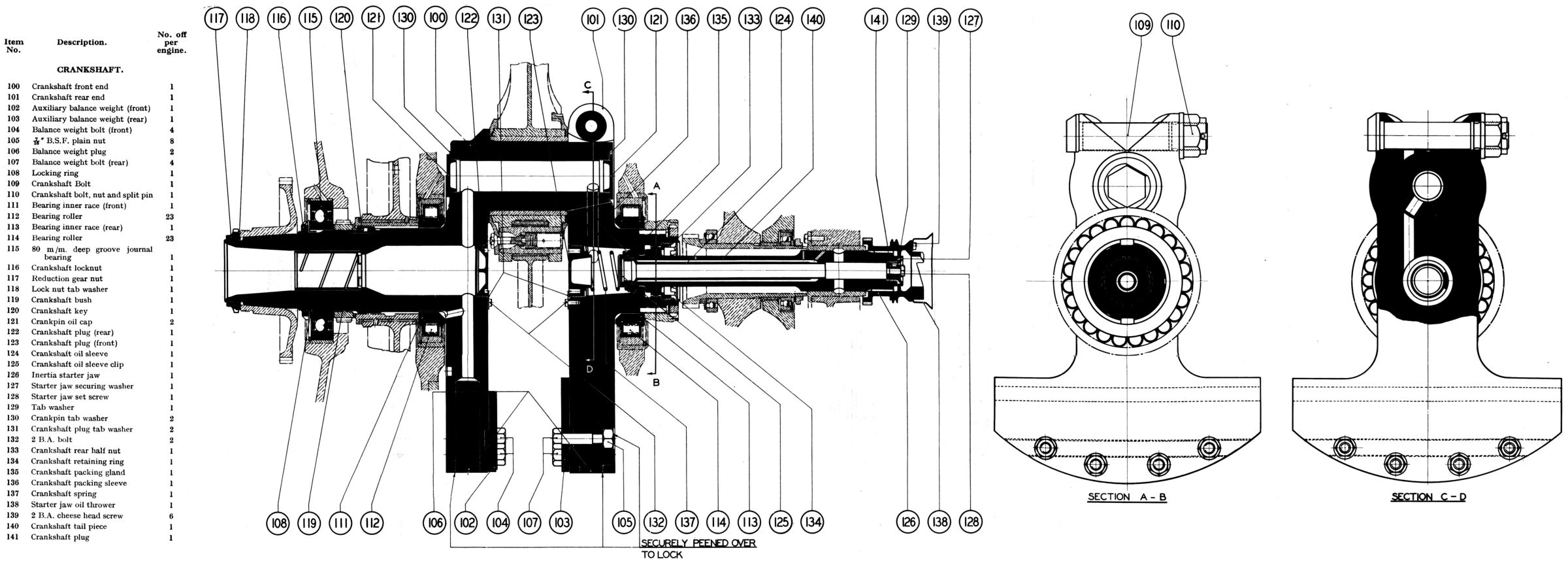 |
| Crankshaft | |
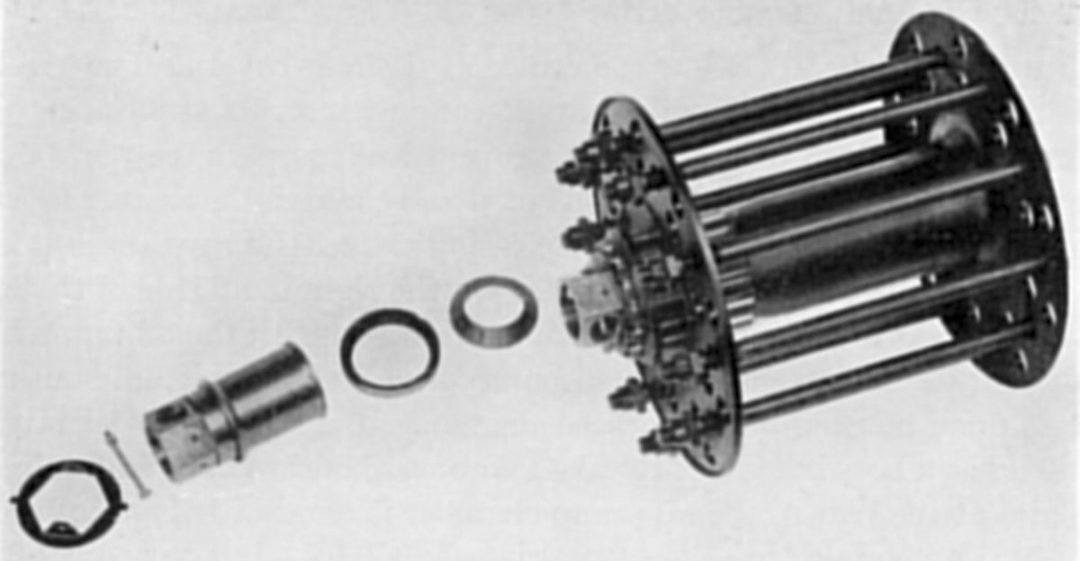
The Crankshaft was a two-piece nickel chrome steel part supported by ball and roller bearings in three places. The webs, whose extensions formed the main balance mass, were fitted with auxiliary balance weights. Each auxiliary weight was located by a tenon slot and four bolts. The auxiliary weights were integral with the shaft since both halves were machined together. The joint between the two crankshaft halves was made at the crankpin rear end where the rear crank web was bored and split to receive the crankpin, which was gripped by a particularly stiff transverse bolt and nut. A key was formed in the coupling bore diametrically opposite to the bolt and entered a corresponding slot in the crankpin extension, thereby locating the two halves. The crankshaft and crankpin were hollow, with the ends blanked by caps. The three main bearings consisted of the front, intermediate and the rear. The intermediate and rear bearings that carried the main journal loads were located against and external to the front and rear crankshaft shaft webs, and consisted of the loose crowded-roller types, the inner races of both being deeply chamfered to clear the radius at the web and the shaft junction. The front bearing was a caged ball bearing that located the shaft axially.
The Front Half Crankshaft forward end had tapered splines machined to receive the reduction gear driving member, which was secured by an aluminium bronze nut and tab washer. Immediately behind this assembly was the front bearing secured by an aluminium bronze nut and tab washer, the cam driving gear, the crankshaft sleeve driven through a key, and the intermediate bearing inner race. Midway along the crankshaft bore was a bronze white-metal-lined bush that constituted the airscrew shaft rear end bearing. It was a press fit in the shaft and the four slots at its inner end provide a means for withdrawal when replacement was necessary.
The Rear Half Crankshaft was quite short, and drove the blower gear and tail shaft. The blower was flexibly driven by a spring drive center through two keys in the shaft; the center was held in position by an aluminium bronze nut. The bore rear end had splines cut to drive the tail shaft, which was secured by a circular slotted aluminium bronze nut. To prevent oil leakage a spring loaded felt packing gland was incorporated in the bore front end, with the oil retaining cap used as the forward spring seating.
The Tail Shaft, which was used to drive various auxiliaries mounted on the rear cover, had a certain degree of universal movement that helped to relieve the crankcase rear cover of all crankshaft loads via the separate tail shaft. Its forward end was driven by the crankshaft splines while the rear end ran in a white metal bearing in the rear cover. Behind this bearing and splined to the extreme end of the tail shaft was the inertia starter jaw, which was secured by a set screw and cap. This part, as its name implies transmitted the torque from the inertia starter when turning the engine. Integral with it were two gears, the forward one a spur gear that provided magneto, gun gear, etc. drive, and the other, a spiral gear, for the oil and fuel pump drives. The tail shaft bore was opened out to a larger diameter in the center and was fitted with a long steel sleeve, the crankshaft oil sleeve, flanged at the mouth to form a seating and a seal. The long annular chamber thus formed was used as an oil passage to feed the blower gear as described later.
 |
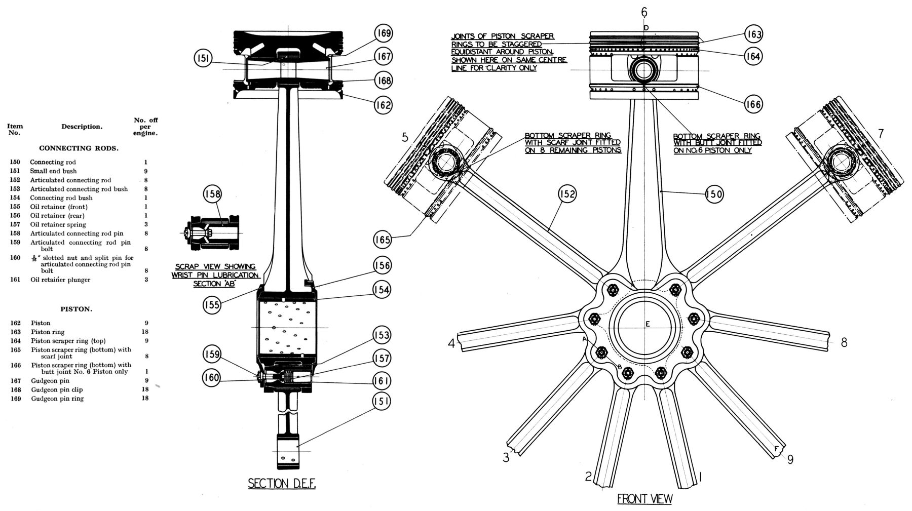 |
| Connecting Rods |
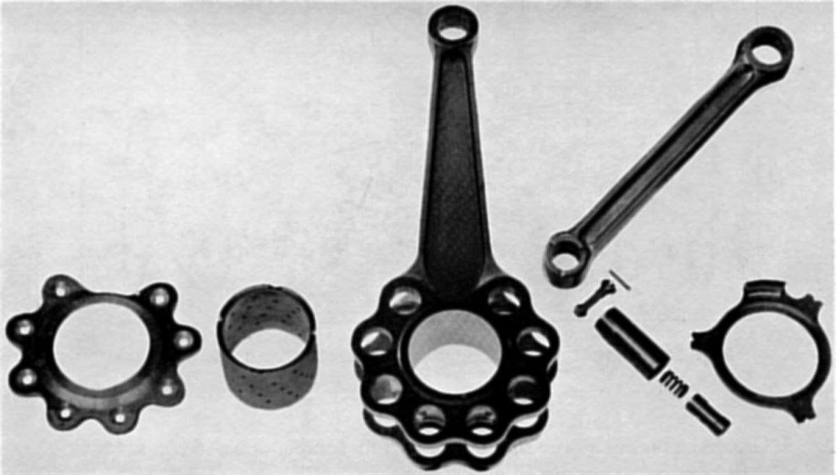
The Connecting Rod Assembly comprised a master rod and eight articulated rods that were secured to the master rod big end by articulated rod pins. The one-piece Master Rod was a nickel chrome steel forging with a deep-H shank section. The two flanges formed around the big end were machined to accommodate the articulated rod pins, which captured the articulated rods between the flanges. A gun metal gudgeon pin bush was shrunk and dowelled in the rod small ends. The eight forged articulated rods were also of H section and had gun-metal bushes shrunk and dowelled in the gudgeon pin eyes, and phosphor-bronze bushes in the articulated rod pin eyes. The gudgeon pin ends were suitably drilled for lubrication.
The Connecting Rod Floating Bush consisted of a steel shell, white-metalled inside and out, to provide a suitable bearing surface for the crankpin and big end bore. The bush was freely drilled to ensure effective lubrication and projected beyond the big end bore on each side. These extensions were used in conjunction with an oil retainer and a thrust ring to provide lubrication to the articulated rod pins as described below.
The Articulated Rod Pins were made from an air-hardened steel. These pins had hollow, bores of reduced diameter toward the forward end to form seats for the short bolts. Externally, the pin forward ends were conical and registered in the master rod taper eyes; they were secured by the aforementioned bolts, which also located the front oil retainer. The pin rear ends located in the rods were slightly larger than the bearing diameters. The articulated rod pins were lubricated via an eight-lobed aluminium alloy oil retainer that was centralized around the big end bush front end. It collected oil from the big end, which then passed through channels cut in the retainer to the front end of the articulated rod pins. The oil was then taken through two obliquely drilled holes in each pin to two oil flats machined diametrically opposite on the outside of the pin, ensuring adequate lubrication. To prevent oil leakage from the rear end a bronze thrust ring or oil retainer was used and was held against the crankpin face by three spring loaded steel plungers These were located in the articulated rod pins and bore against three lugs on the thrust ring, which was prevented from rotating by a tongue registering in the master rod shank.
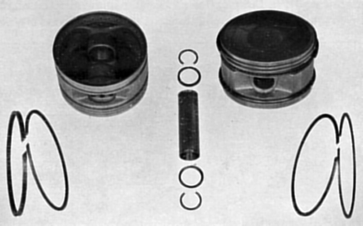 |
| Pistons |
The full skirt Pistons were machined from aluminium alloy drop forgings. They had slightly concave crowns and four cast iron rings, three above the gudgeon pin and one below. The two top rings were compression rings while the third was an oil scraper grooved to a U-section; holes drilled through the bottom of the groove conducted oil to drain holes in the piston at the back of the ring. A freely-drilled groove was machined in the piston immediately below the scraper to assist with oil drainage. The fourth ring, fitted below the gudgeon pin, was also a scraper ring but it exerts much less pressure than the top one, and was beveled at its upper edge. As in the case of the top scraper, there was an oil collecting groove machined in the piston immediately below the ring. The No. 6 piston bottom scraper had a plain square section with a butt joint. This ring gave even less pressure than the other bottom scraper rings thus allowing more oil to the most heavily loaded cylinder walls. This ring had a butt joint versus the compression rings that had 45° scarf joints.
A hollow full-floating Gudgeon Pin of air-hardened steel was a working fit in the piston bosses. It was retained by an air-hardened steel ring at each end, and these rings were secured by circlips in suitable grooves. One side of each ring was chamfered to accommodate the circlip, the other face being square to butt against the piston boss. It was of such thickness that incorrect assembly was not possible. Ample end clearance was allowed on the pin to provide for piston expansion. The gudgeon pin was lubricated via holes in each gudgeon pin boss, and by holes in the connecting rod small ends and the small-end bush.
 |
 |
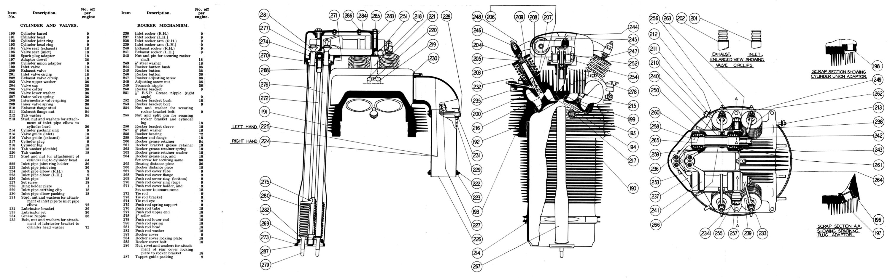 |
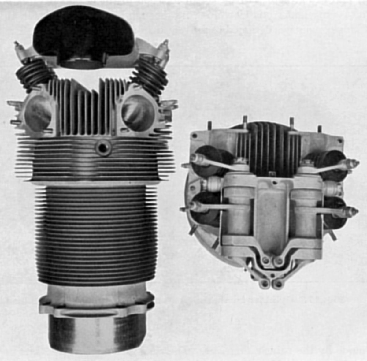
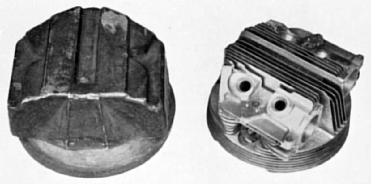
| Cylinder and Rocker Mechanism | Cylinder Head Forging, Complete | Cylinder, Valves, Rocker Mechanism |
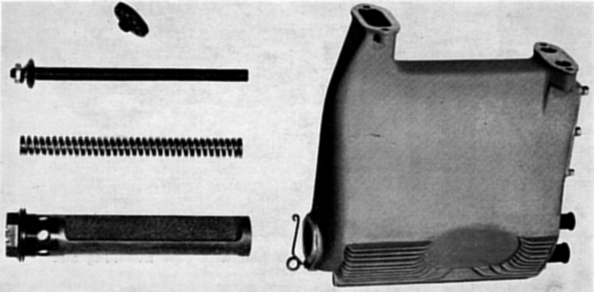
The Cylinder consisted of a steel barrel to which a drop forged Y-alloy head was screwed and shrunk. Two inlet and two exhaust valves were fitted. The cylinder barrel was finned for most of its length, the lower end being plain and forming a spigot location in the crankcase. It was bolted to the crankcase by eight studs that passed through four pairs of lugs in an otherwise circular flange; the design helped prevent distortion of the barrel. The crankcase joint was sealed by a rubber ring. Clearance slots in the skirt were of equal depth and all cylinders were interchangeable. The cylinder barrel top end was threaded to join the cylinder head, and a copper jointing ring fitted into a recess in the head ensured a gas-tight joint. After the head was screwed and shrunk onto the barrel, it was finally secured by a grip band shrunk on and turned to form the lowest fin on the head.
The machined-all-over Cylinder Head was heavily finned both horizontally and vertically to ensure efficient cooling. The pent-roof combustion chamber had two 3-stud exhaust facings in front and two rear-racing 2-stud inlet facings that attached to cast inlet pipe elbows. The inlet pipes were aluminium tubes flexibly positioned at the top and bottom. A small steel clip fitted on one stud at each end of the inlet pipe established electrical continuity prevent the pipe from being insulated by the rubber ring, thus conforming to the requirements of electrical bonding. The four valve seats were screwed and shrunk into the head before final machining. The phosphor-bronze valve guides were pressed in cold. Two spark plugs screwed into bronze adaptors that were diametrically opposite on the cylinder transverse center lines. Another screwed adaptor approximately midway between the two plugs was for the gas distributor cylinder union. Two bronze-bushed pillars were attached to the top of the head by three studs each; these formed the rocker gear anchorage. Four valves were of a special steel with nitrided stems. The exhaust valves were of a slightly heavier construction. The inlet valves had slightly larger heads but smaller diameter stems and narrower seats. Pressed into the end of each valve stem was a hardened button that provided a working surface for each rocker screw. Three concentric springs were fitted to each valve and were located between upper and lower washers. The upper washer was secured by a split cotter bearing in a conical seat. A wire circlip below the cotter prevented the valve from falling into the cylinder. Valve guide lubrication was achieved via a small bracket bolted to the top fin near the valve guide, which carried a grease nipple and a small diameter tube connected to a hole drilled in the valve guide. One lubricator was fitted for each guide. Four drilled lugs in the two top fins of each cylinder facilitated cowl ring attachment.
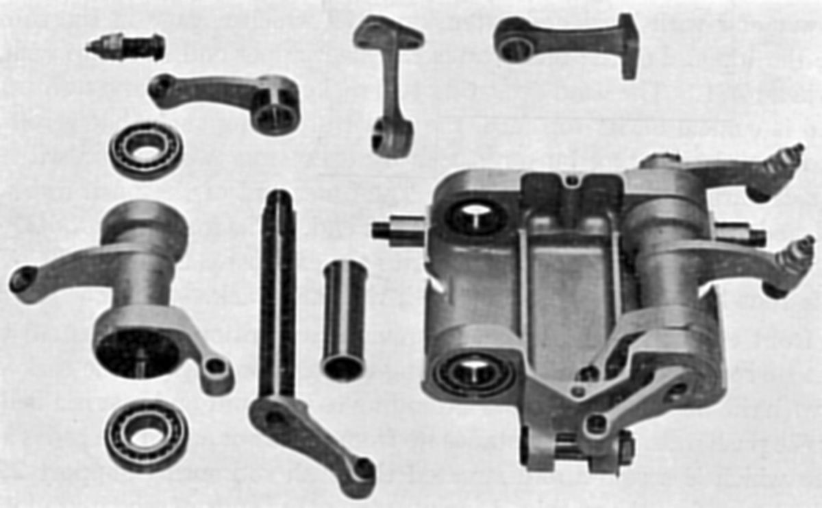 |
| Rocker Mechanism |
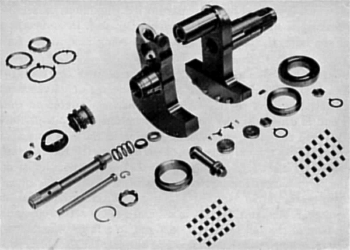
The Rocker Mechanism was suspended at three points. At the rear end the unit was anchored by and could pivot about two rocker pillars located on the cylinder head's transverse center. The forward end was secured by the tie rod, which was screwed and sweated into a base plate that attached to the crankcase. The rockers were operated through push rods and the unit was enclosed in covers and casings. Two parallel sets of concentric rocker shafts were mounted on ball bearings housed in a steel rocker bracket. On the sides of this bracket and integral with it were trunnions located in the previously-mentioned rocker pillars. Each shaft set (one set was right handed, the other left handed) comprised inlet and exhaust rocker arms, which were supported by ball bearings at each end. The shaft of each inlet rocker assembly ran its full length and carried four ball bearings; at the front end and integral with the rocker was the arm operated by the push rod. At the rear end of each inlet rocker and splined to it was the inlet rocker arm, which carried at its outer end the rocker adjusting screw. Interposed between the front and rear rocker bracket bearing housings, and concentric with the rocker shafts were the exhaust rockers. Each rocker was carried on two bearings (one at each end) that were separated by a distance piece (spacer). At the forward end of each rocker an integral arm made contact with the push rod, while at the rear another integral arm operated the exhaust valve through an adjusting screw. Grease retainers assisted bearing lubrication, while at the rear end was a spring loaded oil retainer. The rocker adjusting screws had large floating buttons at their lower end. The shanks of the buttons were a loose fit in the screw bores and were peened over at their inner ends sufficiently to retain them in position when the rockers were dismantled, but allow a small end movement. Screwed caps with grease fittings enclosed the screw top ends. Similarly, floating buttons at the ends of the front rocker arms transmitted push rod motion; although they were floating these were not adjustable.
The cam lift was transmitted to the rockers through push rods in the cylinder fronts. The push rods were nickel chrome steel tubes closed at the lower end with hardened extensions that engaged in the cam tappets. A steel upper end was fitted into the tube and formed the push rod head. The head operating two rocker arms was enlarged to a mushroom shape and was conical on its top face, the curvature creating a rolling action on the rocker floating button; two rockers were operated with one push rod, with the side thrusts balanced out. The inner end of the push rod head bore on a hardened roller in the push rod upper end. The front push rod operates the inlet valves, while the rear push rod operated the exhaust valves. Springs at the rod lower ends kept them in contact with the cam track.
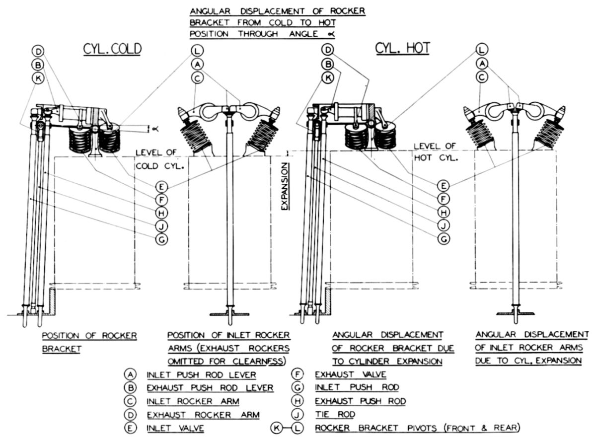 |
| Valve Clearance Compensation |
The front end of the assembly was secured to the top end of the tie rod by a bolt passing through two lugs on the rocker bracket. Integral with the tie rod eye and extending to the front and rear was a bell mouthed guide for the push rods. Some distance up from the lower end of the rod was a threaded portion to which was screwed and sweated the push rod spring support, which secured the push rod spring top ends, the other ends of which were located on a flange on the push rod lower ends. The rocker assembly was covered with a cast magnesium cover. An aluminium tube shaped at its lower end protected the push rods while rubber rings provided seals at the top and bottom ends.
At working temperature, the cylinder expanded while the push rod lengths were essentially constant; this would have caused excessive valve clearances. Compensating gear was designed to obviate this variation and accomplished its purpose by maintaining the relation of the rocker assembly front end and the crankcase practically constant by means of the tie rod. As a cylinder expanded the rocker assembly anchorage rose with it and imparted to the longitudinal rocker shafts an angular movement about the forward tie rod eye, thus giving a transverse angular movement to the rocker arms. Since the inlet rocker shaft overhung both the front and rear rocker bracket pivot points, when the cylinder expanded the inlet rocker was raised slightly. This would have increased clearance between it and the valve if the same bracket movement had not lowered the push rod at the front end (relative to the cylinder) an approximately equal amount, with the result that the changes at each end cancelled out and the total clearance was virtually unaffected. The same principle applied to the exhaust rockers except that since the push rod arm and rocker arm lie between the pivot points, the tendency (if not corrected) would be to decrease the clearance. When the cylinder was cold the rocker bracket was not at right angles to the cylinder axis – the front end was raised to a maximum of 1° (minimum 2°) away from the crankcase face. The bracket assumed a level position when the working temperature was reached, thus making the path of the rocker true with the valve.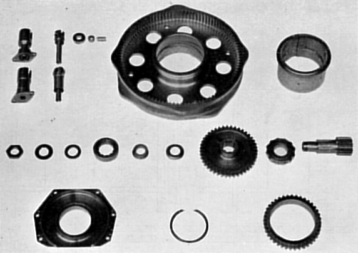 |
 |
 |
 |
 |
| Cam Unit | Cam Sleeve and Tappet Gear | |||
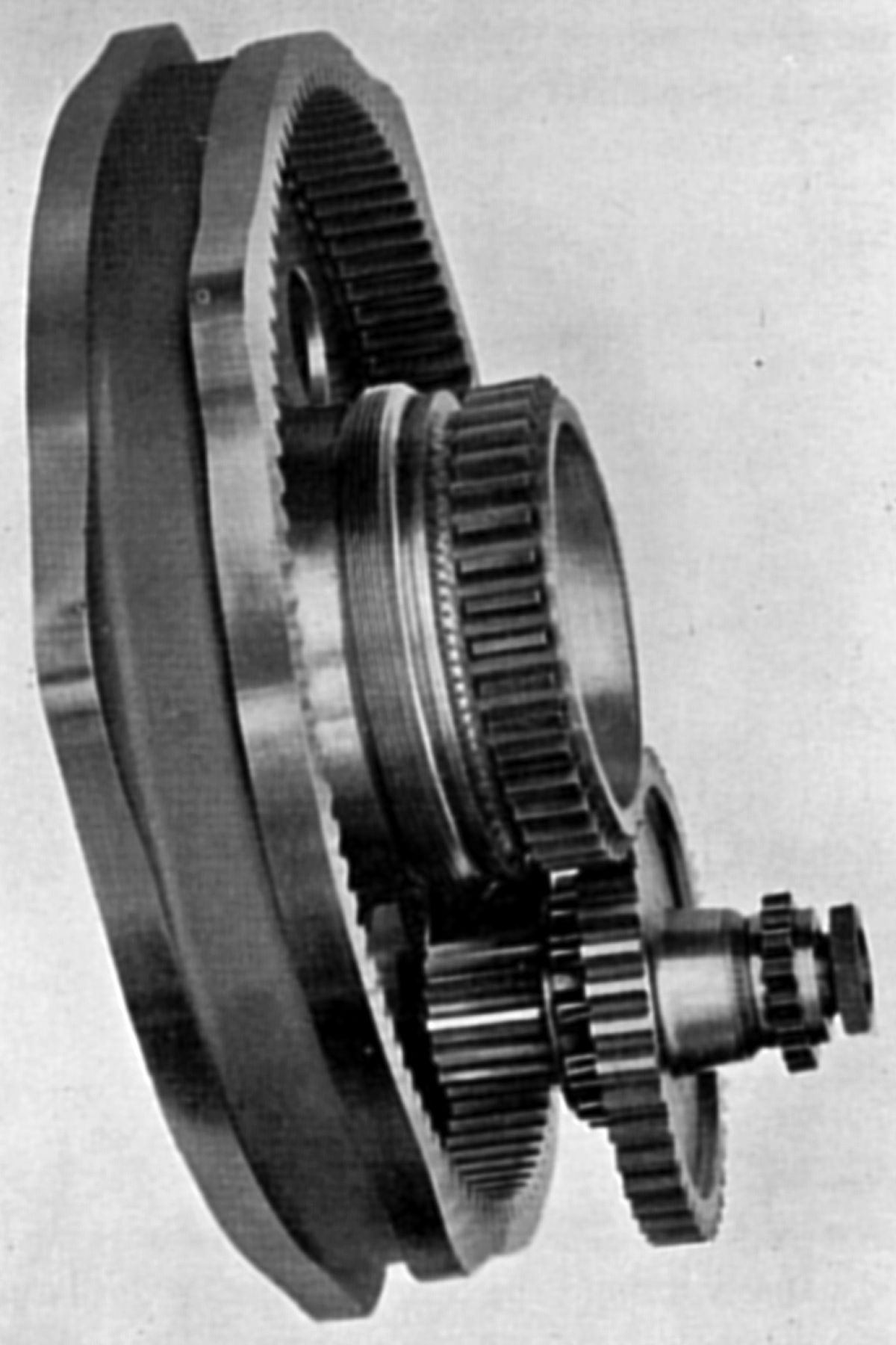
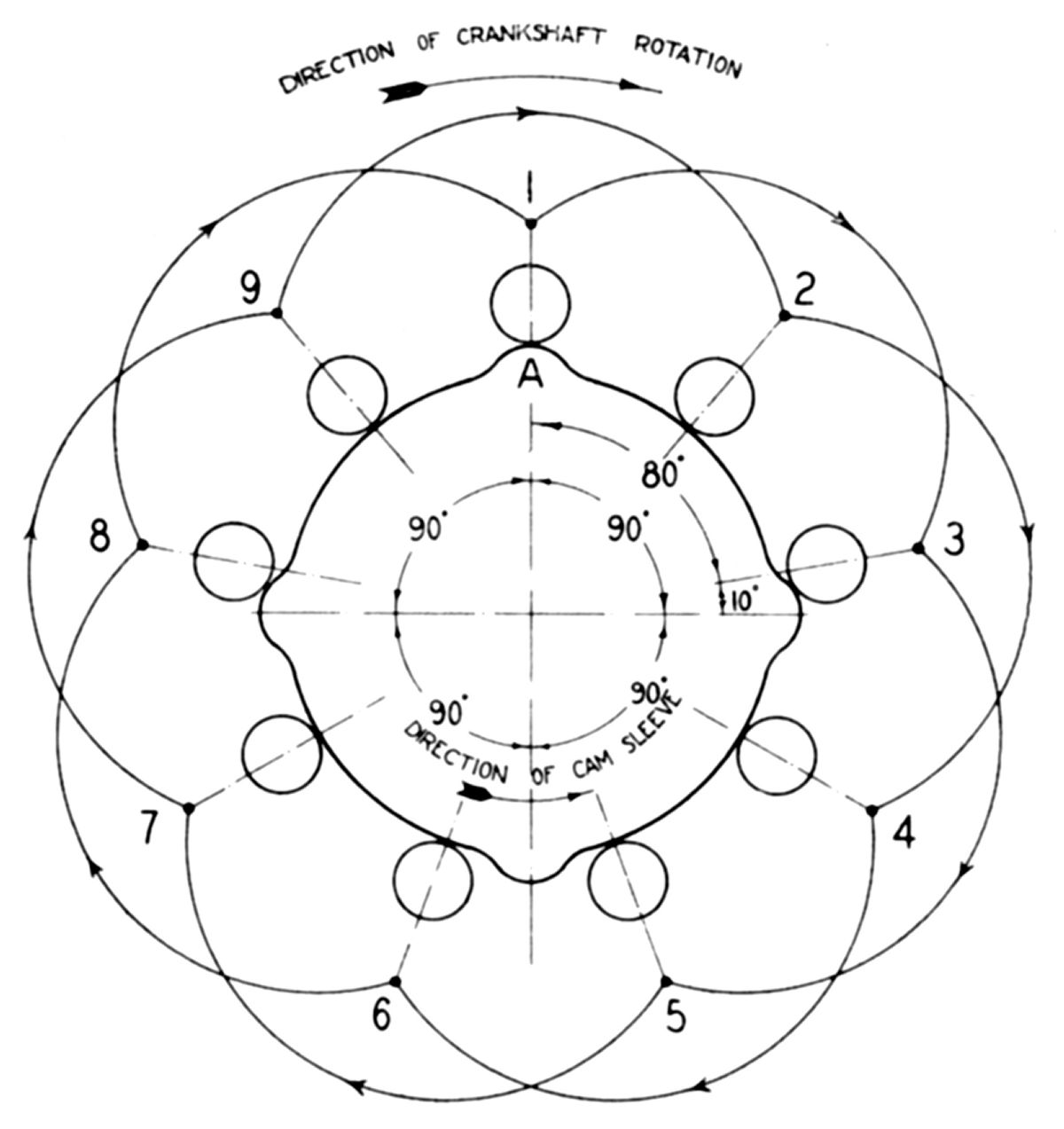
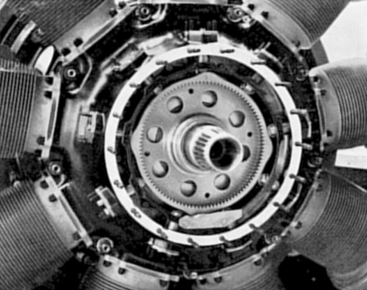
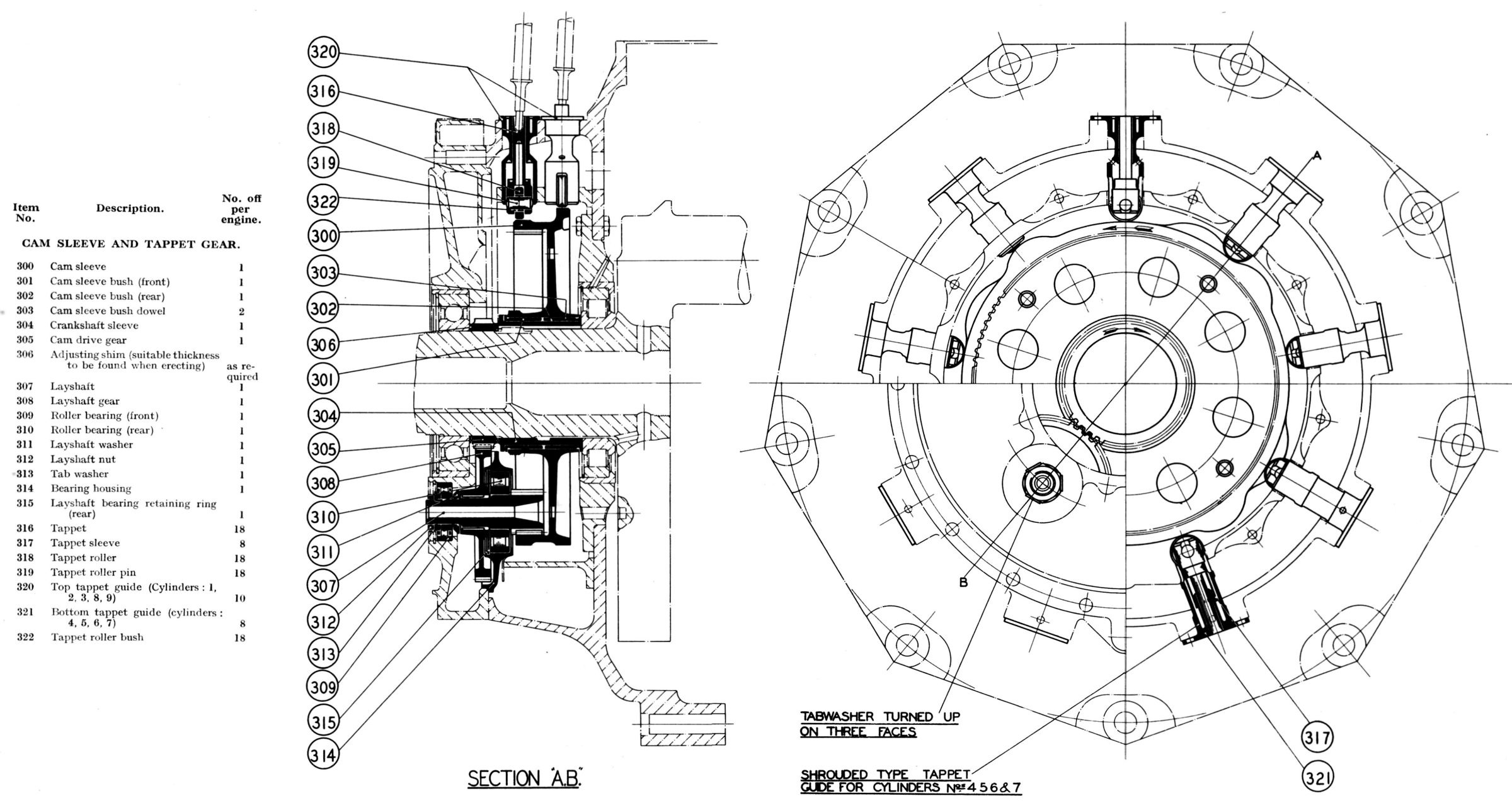
The Cam Gear Assembly, driven by spur gearing through a layshaft, rotated concentrically around the crankshaft and operated nine sets of radially disposed tappets. Keyed to the crankshaft front half and adjacent to the main roller bearing was the hardened crankshaft sleeve, the bore of which had a white metal coating to protect the crankshaft. Upon this rotated, in the opposite direction, the cam sleeve with its phosphor-bronze bushes that were a press fit in the sleeve and secured by brass dowels. The cam sleeve had four pairs of lobes on its outer periphery with the front row operating inlet valves and the rear row exhaust valves. An internal spur gear was machined inside the cam track. The cam sleeve front end boss was threaded to facilitate withdrawal. Driven through serrations at the crankshaft sleeve front end was the cam drive gear, which was located directly on the crankshaft. Interposed between the gear and the front thrust bearing were adjusting shims used to centralizing the connecting rod assembly. These were necessary to compensate for accumulated assembly tolerances.
The Layshaft Assembly was supported in two roller bearings located in the crankcase front cover. Splined to its center was the layshaft gear, which was driven by the cam drive gear. Integral with the layshaft rear end was a spur gear that engaged the cam sleeve. The layshaft rear bearing was kept in its housing by a circlip, the housing itself being fixed to the crankcase front cover inside by six studs. The front bearing, the inner race of which was split to assist assembly, was housed in the crankcase front cover. The special roller bearings used permitted a small angular layshaft movement to take up any slight flexure that may have occurred in the cam sleeve during operation, thus preventing any localization of stress on the pinion teeth.
The Cam Gear Train began with the 39-tooth cam drive gear, which was driven at crankshaft speed. The 42-tooth layshaft gear with 42 teeth rotated 39/42 times that crankshaft speed. The 14-tooth layshaft gear, splined to the layshaft, rotated at the same speed, and meshed with the 104-tooth internal cam sleeve, giving it a speed of 39/42 x 14/104 = 1/8 crankshaft speed in the opposite direction.
Nine pairs of case-hardened Tappets working in phosphor-bronze guides were mounted radially around the cam chamber. The tappets were hollow and were slotted at their inner ends to receive case-hardened steel rollers. The rollers were fitted with floating phosphor-bronze bushes, which were free to rotate upon hardened pins. The tappets on cylinder Nos. 4, 5, 6 and 7 had a spigot behind the head to which a brass sleeve was sweated; this prevented over-oiling those fitted to the lower cylinders. Tappet guides, flanged at their outer end, were secured to the crankcase by two studs each; the inner end was located in a ring secured to the crankcase wall. As in the case of the tappets, the bottom tappet guides fitted to cylinder Nos. 4, 5, 6 and 7 had a larger center portion diameter that accommodated the sleeve on the tappet. They were specially drilled to provide effective oil drainage, as was the crankcase to provide an oil return to the sump.
 |
 |
 |
 |
 |
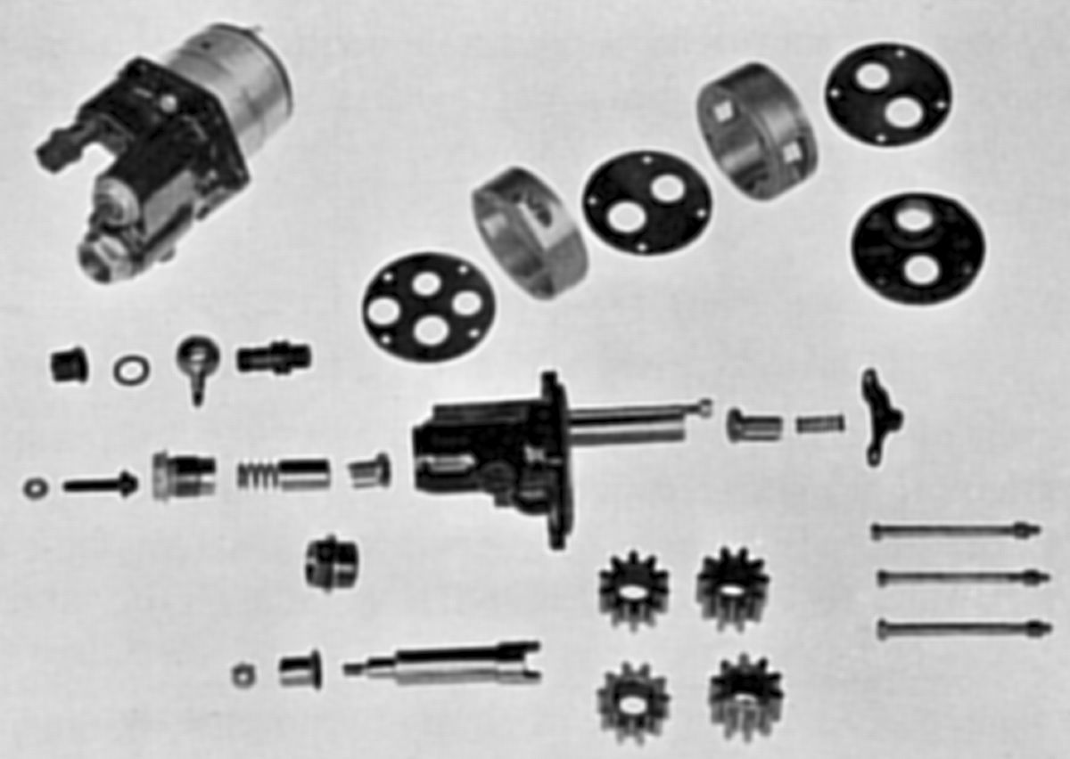
| 0.5:1, 0.666:1, 0.666:1, 0.5:1 and 0.666:1 Reduction Gears | Reduction Gears and Airscrew Hub | |||
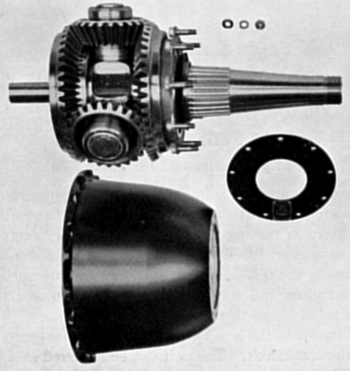
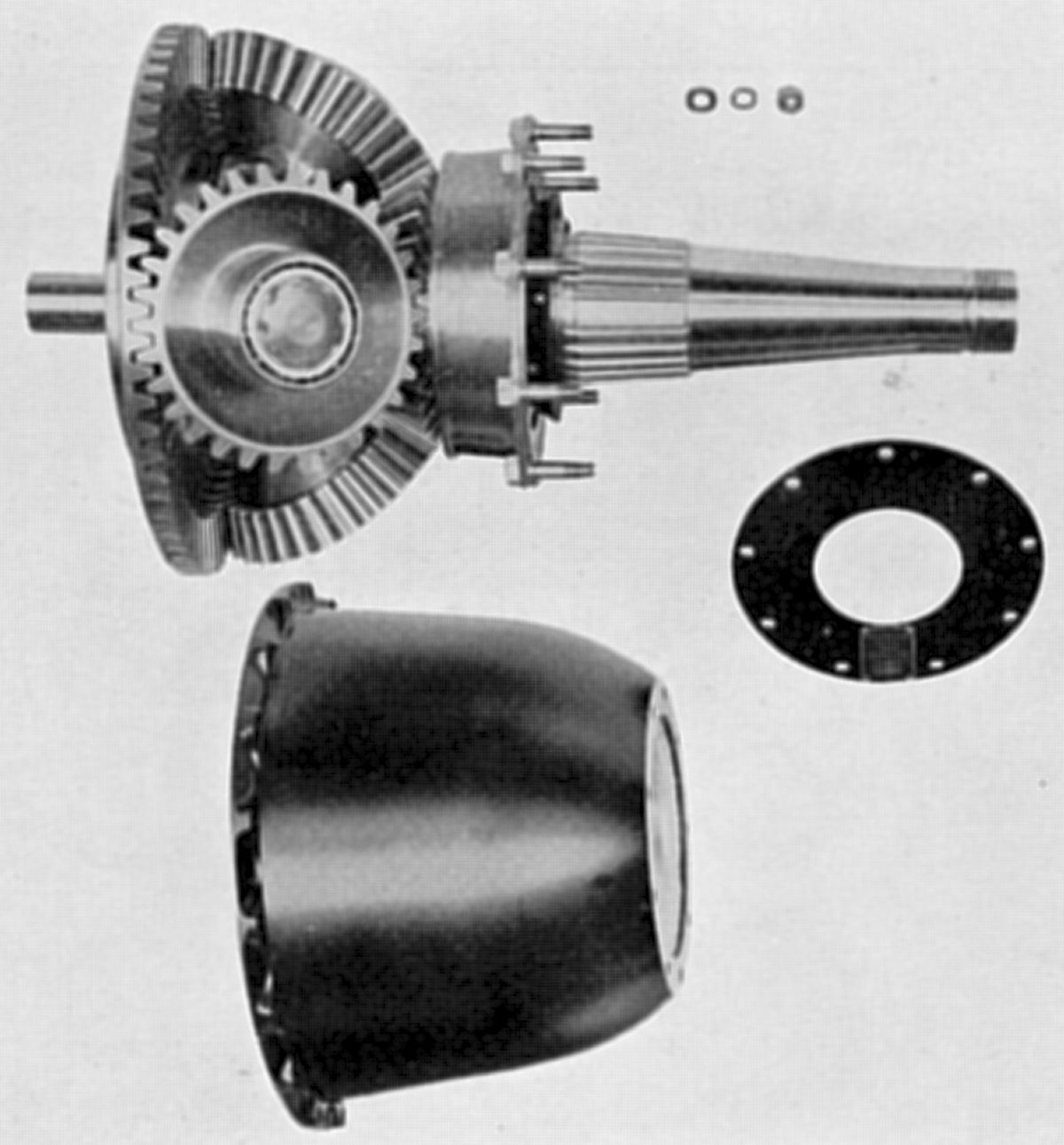
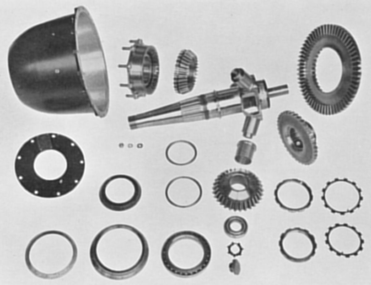
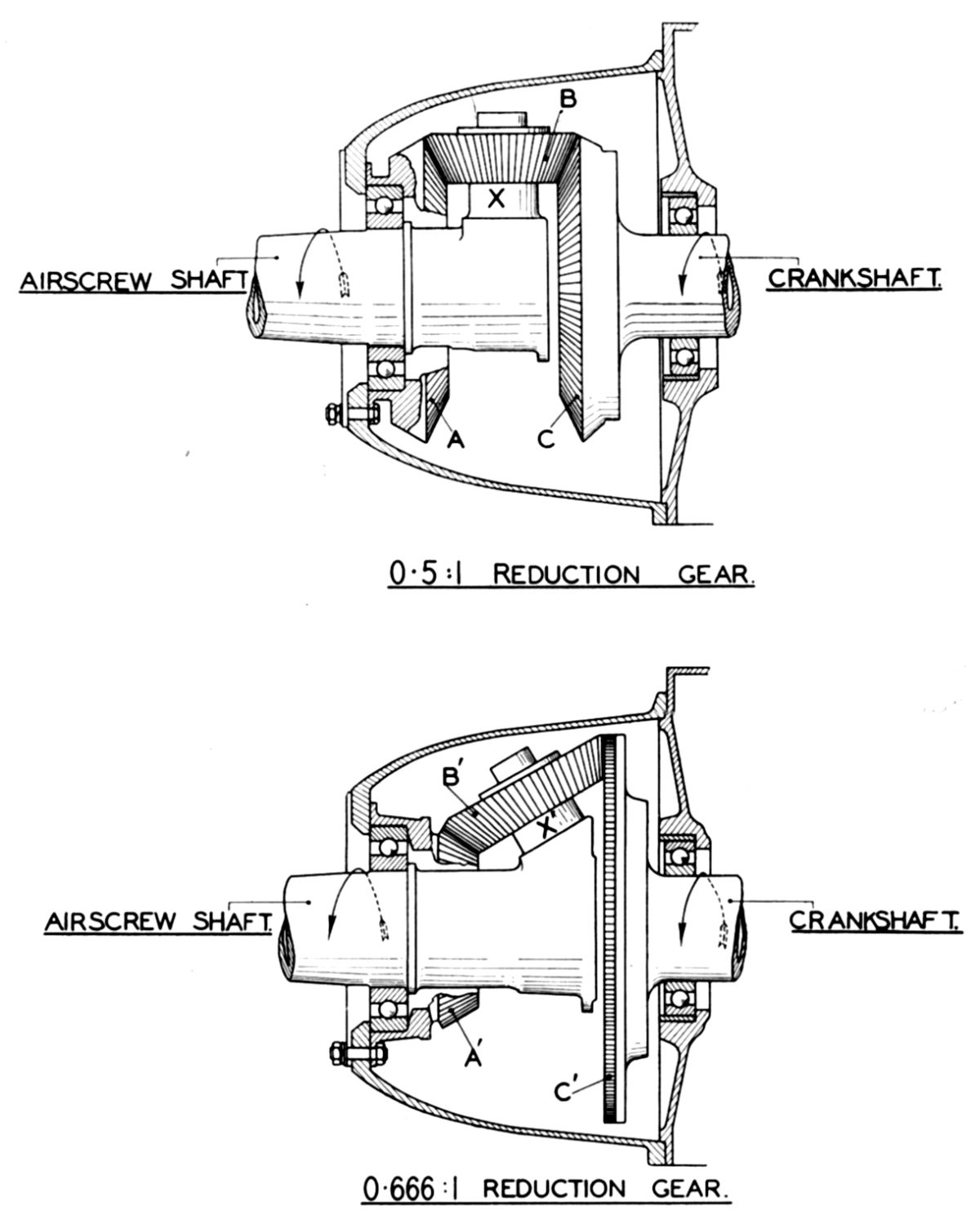
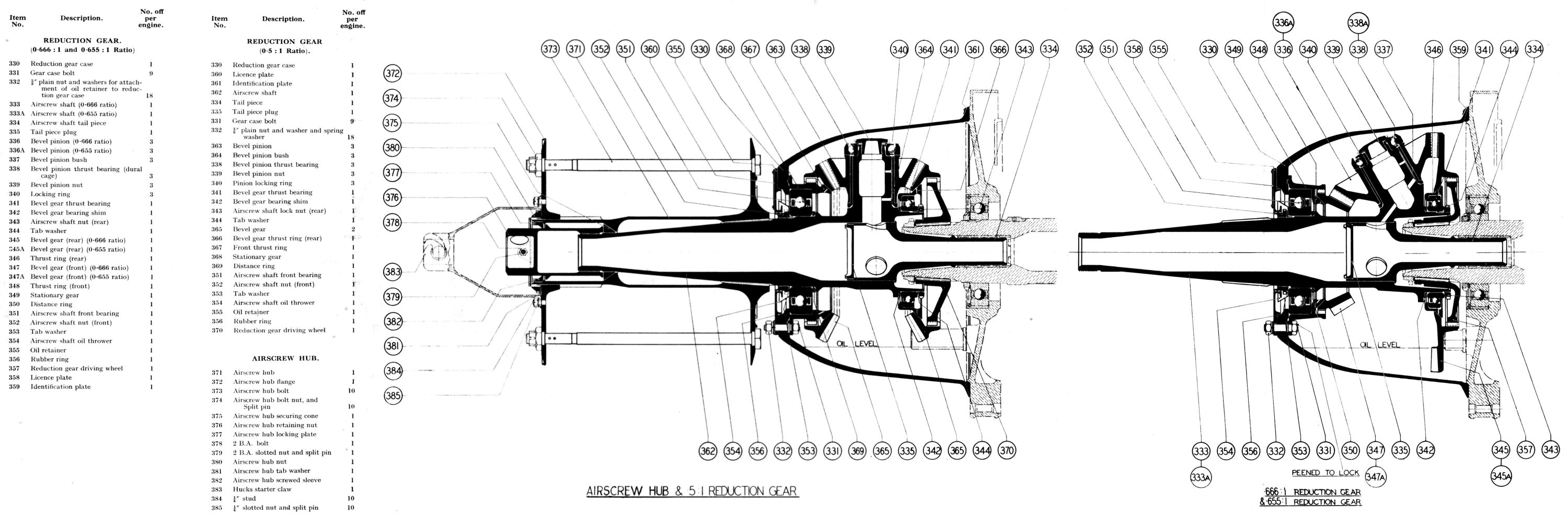
The Reduction Gear Unit featured two interchangeable airscrew reduction gear ratios – 0.5:1 and 0.666:1; some earlier engines had a 0.655:1 ratio. The Reduction Gear Unit used bevel gear to cause the propeller center line to be co-axial with the crankshaft center line. The unit could be removed as a whole by releasing the 18 nuts that secured it to the crankcase front cover. The gearing consisted primarily of two opposed bevel gear wheels, the front one of which was anchored to the gear casing, and the rear one rotated by the crankshaft through a driving member. Three bevel pinions, freely mounted upon equally spaced stub arms radiating from the airscrew shaft ran between the bevel wheels and engaged both. The crankshaft rotation with its bevel wheel caused the three stubs and therefore the airscrew shaft to be carried round at reduced speed. An important design point was the provision for equal load distribution over the three pinions, which was obtained by providing floating mountings for the bevel wheels instead of rigid attachments.
The short stiff Airscrew Shaft was produced in two pieces, the airscrew shaft and the tail shaft. The tail shaft, common to both gear ratios was shrunk into the airscrew shaft and regarded as integral with it. The complete shaft was supported at the rear end in a white-metal bearing in the crankshaft front end bore, while the airscrew front end was carried in a deep grooved ball bearing that served the dual purpose of a journal bearing, and a thrust bearing by which the airscrew thrust was transmitted to the engine. A shoulder on the shaft behind the front bearing located the inner race. Interposed between the shoulder and the inner race was an adjusting shim. The bearing was secured to the shaft by an aluminium bronze nut with a left hand thread that was secured by a tab washer. Forward of the bearing and outside of the reduction gear casing, the shaft was machined to a taper and splined to receive the airscrew hub and was threaded to receive the airscrew hub nut.
At the shaft's rear, three short arms radiate from the centre; the 0.5:1 reduction gear arms were at 90° to the shaft and the 0.666:1 ones were inclined at a 60° angle. Behind these stub arms the shaft proper overhung the tail shaft, and was increased in diameter to take the bevel gear thrust bearings, which were secured to the shaft by aluminium-bronze nuts and tab washers. Interposed between the bearing and the shoulder adjacent to the stub arms was a distance washer (shim) required to obtain the correct gear teeth backlash. The shaft was hollow for its whole length, but was blanked off about half-way along the bore at the tail shaft front with plug; this plug was tinned and screwed to the shaft, making it a permanent part thereof. The stub arms were also lightened by suitable boring.
The three bevel pinions rotated upon white-metal lined steel floating bushes, which were flanged at their inner ends and abutted shoulders on the stub arms. The bush for the 0.5:1 gear was longer than for the 0.666:1. The outer end of the bevel pinion boss abutted a special ball bearing, the inner race of which fitted on a spigot and against a shoulder at the stub arm end. The race was held in position by a blank cap screwed into the arm bore and locked by a tab washer. The bevel pinions engaged rearward with the rear bevel gear, which was mounted on a spherical aluminium-bronze thrust ring. The ring for the 0.5:1 gear was longer than for the 0.666:1 gear. The thrust ring that surrounded the thrust hearing extended forward to a shoulder, the rear face of which abutted the bearing. A clearance between the bearing outer race and the thrust ring bore allowed the thrust ring and bevel gear some degree of self-alignment. The bevel gear rear was internally splined to engage the driving member. Sufficient spline clearance allowed a small universal movement of the bevel gear. The driving member was attached to the crankshaft by tapered splines, and the boss forward end was threaded to facilitate withdrawal. The bevel pinions engaged at the front end with a fixed bevel gear, which again was not rigidly fixed but mounted on a spherical aluminium-bronze bearing that permitted slight universal movement that allowed the gear to find its normal working position. A forward extension to the fixed bevel gear was splined to anchor it to a housing that was bolted to the reduction gear case forward end by nine studs and housed the airscrew shaft bearing. In the 0.5:1 gear a bronze thrust ring abutted its rear face, while in the 0.666:1 gear an internal lip in the housing positioned the thrust ring.
A drop forged aluminium alloy Reduction Gear Casing common to both gear ratios was located by a spigot to the crankcase front cover and was secured by 18 studs. The casing front was closed by a cover plate with a rubber oil seal ring. The thrust bearing nut forward end was extended to provide a left hand spiral groove (labyrinth seal) that completed the seal. An oil thrower between the front bearing and its retaining nut deflected surplus oil, which drained back into the casing by suitably drilled holes.
The 0.655:1 Reduction Gear differed with the 0.666:1 gear by the gear tooth counts and stub arm angles of the airscrew shaft. The 0.655:1 arms were set at a slightly steeper angle, while the bevel pinions and the rear bevel gear had 28 and 57 teeth as compared with 30 and 60 teeth on the 0.666:1 gear. The fixed bevel gear had the same number of teeth as that of the 0.666:1 gear, but the cone angle was altered to suit the pinions and was also slightly wider than the 0.666:1 type. The bevel pinion thrust bearings were assembled with distance washers interposed between the inner races and the shoulder on the stub arms. In later gears the washer was deleted and the inner race width increased accordingly. Otherwise, the two reduction gear types were the same. In all three reduction gears the number of bevel pinion teeth had no effect on the speed ratio, which was determined by the fixed bevel to driving bevel tooth ratio
 |
| Airscrew Hub |
The Airscrew Hub, which normally fitted a ten-bolt wooden airscrew, was machined from a nickel chrome steel forging and was in the form of a long barrel that developed at its rear into a large diameter flange. The flange base was considerably stiffened to form a boss in which tapered splines were machined for securing the hub to the airscrew shaft. The hub forward end was also splined on its outside diameter to fit the front flange. The hub was hollow with an internal shoulder formed in the bore some distance from the front end, the front face of which was conical to fit a phosphor-bronze split securing collet. The collet, which was freely mounted on the crankshaft, acted as a stop and transmitted force from the aluminium-bronze retaining nut to the hub when it was assembled on the shaft. The retaining nut was locked by a tab washer having two tabs on the outside that engaged in slots in the front end of the hub, while a hexagonal aperture in its center fitted over the nut's hexagon and a bolt passed through two flats of the nut and two tabs of the washer, effectively securing it. Provision was made for withdrawing the hub by a left hand threaded sleeve that was screwed down to a stop in the airscrew hub bore front end. By unscrewing the retaining nut a shoulder on the nut pressed against the screwed ring and continued unscrewing drew the hub from the shaft. No provision was made for locking the screwed sleeve as the direction of hub rotation made the sleeve self-locking. The front airscrew hub flange was the same diameter as the rear and had a narrow boss, the bore of which had parallel splines to correspond with those on the hub front end. It was free to move longitudinally within set limits to accommodate varying airscrew boss widths. It was retained on the hub by a steel nut that was locked by a tab washer. The 10 bolts that secured the airscrew were threaded for a considerable length to allow flange adjustment. Slotted nuts spigoted to fit the flange holes were used. To prevent the bolts from turning, one of the flats on each bolt head located on a spigot on the rear flange rear face. A Huck's starter claw, located on a spigot and secured by 10 studs to the front flange could be fitted when this starting method was desired. The claw had to be special-ordered.
 |
 |
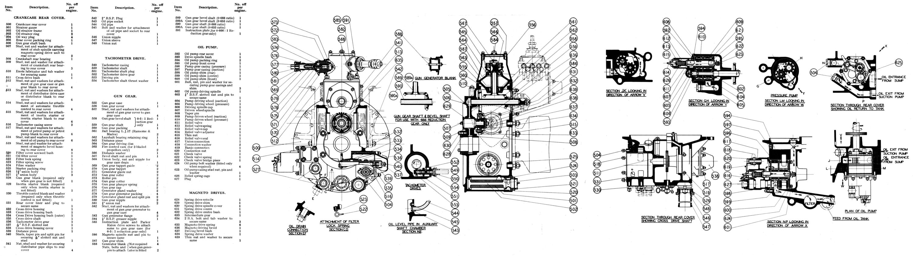 |
| Rear Cover | Rear Cover, Oil Pump, Auxiliary Drives | |
The rear cover was a magnesium casting located on a spigot and attached to the volute casing by 12 studs and a rubber sealing ring. A boss in the casting rear wall housed the crankshaft rear bearing, a flanged phosphor-bronze white-metal lined shell secured by 3 studs. Immediately above this the rear cover wall was bossed up to take the magneto drive fixed flanged spindle, while above that again was another boss for the gun gear shaft bush, a flanged magnesium bush pressed into the casing. The top part of the casing was formed into a square housing in the top of which was an aperture for the gun gear casing. The housing rear face was also machined and bored to form a 6-stud facing for the distributor drive casing. Below this and on the casing center line was another 6-stud facing but of larger diameter to which the inertia starter was attached. Between the two facings just mentioned and at right angles to them were two more 3-stud facings, one on each side, for the magnetos. An inner wall was also bored and faced for the final magneto drive.
Below and left of the rear cover center was the oil pump housing with its 6-stud facing. A magnesium liner was fitted to the bore to prevent leakage past the ports in the rear cover casting. Suitable oil ways were machined and cored in the casting for supplying the pump. On the oil pump casing outside and extending rearwards was a facing for the automatic throttle control bracket. On the rear cover right side opposite and in line with the oil pump housing was the tachometer and fuel pump drive housing. A magnesium cross drive housing was located therein. It was secured by 6 studs and at its inner end had a boss bored out to take two bronze bushes. In line with this boss and at the oil pump chamber rear was another boss, also bushed with two bearings that supported the cross drive shaft. Interposed between them and integral with the shaft was a spiral gear that took its drive from a gear on the crankshaft. An oil level for the gear was maintained under climbing conditions by an oil drain pipe attached to the wall by a socket plate.
The cross drive shaft had a pair of dogs at one end for driving the oil pump, while the other end of the shaft drove the tachometer and fuel pump. The tachometer driving gear was mounted on the shaft adjacent to the bearing. Next to this was fitted a bevel gear (if the flexibly-driven fuel pump was used), or a driving sleeve (if the direct-drive pump was fitted) or a plain sleeve if neither were fitted. The shaft was hollow and carried oil to the tachometer gear and fuel pump drive. A stud and a nut, specially drilled to allow oil to percolate through to the bevel gear, was fitted to the shaft end. When no fuel pump was fitted, a blanking cover closed the drive end.
At the rear cover bottom and extending the whole length was an oil filter chamber, threaded at its outer end to receive a sleeve into which in turn was screwed the filter cover , which was locked by a spring clip. The filter, which consisted of a brass gauze mounted in a tubular frame, spigoted into the filter cover end while the other end located in a recess in the rear cover casting. To the right of the oil filter cover was the oil feed union, a cored passage connecting it to the filter chamber. On the left side of the filter chamber was another union connected by a passage in the cover to the pressure side of the suction pump. A pipe from this point bypassed oil through the carburettor body before returning to tank. At the rear cover top, in front of the gun gear drive housing, was an oil nipple for priming the blower rear bearing after the engine had been standing for a long period.
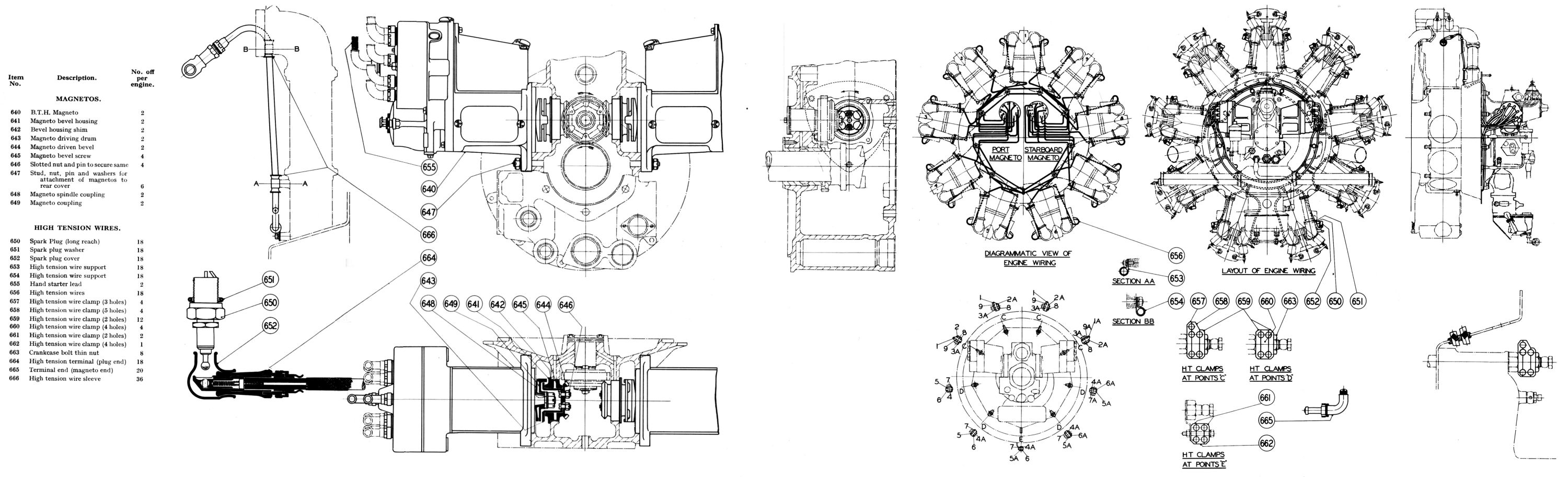 |
| Magnetos and High-Tension Wires |
Dual ignition was provided by two B.T.H. SC9-5B magnetos transversely mounted the on the engine rear cover. Both magnetos were driven from a single spring drive which in turn was driven by the crankshaft. A fixed flanged spindle secured by two studs was mounted in the rear cover above the crankshaft. The smaller-diameter rear end had a magnesium bush located on it, and upon this was mounted the spring drive center, to which was attached the intermediate gear. This gear engaged a spur gear on the crankshaft and since both had the same number of teeth the spring drive rotated at engine speed. Mounted on the spring drive boss and located against a shoulder was another magnesium bush upon which was positioned a bevel gear. The four parts thus mounted on the spindle were retained by a special washer. The three tapped bosses formed inside the intermediate gear acted as driving dogs, while three similar dogs on the bevel gear took up the drive through coiled springs, thus forming a flexible drive that damped out the uneven magneto torque. Under normal running the coils of the springs butted and a solid drive was obtained.
The bevel gear droves two other gears that were at right angles to, and disposed on each side of it. These in turn were directly coupled to the magnetos. Adjustment for the gears was provided by laminated brass shims located between the rear cover and the flanges on the driving spindles. The magneto gears were bolted to the steel driving drums that ran in magnesium housings. The drum outer ends were flanged and had two slots, each of which engaged steel couplings. These couplings had serrations on their outer faces that engaged similar serrations on the magneto spindle couplings and provided a fine adjustment for the magnetos. The spindle coupling bosses had tapered bores that fitted the magneto spindles to which they were attached, the drive being taken through two keys.
The intermediate gear and attached bevel gear rotated at engine speed. This driving bevel had 36 teeth and drove the two magneto bevels with 32 teeth and the magnetos at 9/8 crankshaft speed. This was necessary because the magnetos give four sparks per revolution and nine cylinders require to be fired in two revolutions. Both magnetos rotated anti-clockwise looking at their driving ends.
Each magneto carried nine high tension wires in addition to a central one for starting and fireed one spark plug in each cylinder; the port magneto fired the plugs on the left cylinder side and the starboard magneto fired plugs on the right cylinder sides. The high tension wires issued from the magneto distributor board through tubular right-angle elbows, and then through light alloy clamps attached to the nine crankcase bolts. In the case of the bottom bolt, however, the clamp was not fixed directly on it, but was attached to a plate that was fixed to the bolt. The wires then passed through the cone mounting ring and were prevented from chafing by rubber bushes. They were then secured to the inlet pipe tops and bottoms by suitable clips, before final connection with the spark plugs. The high tension wire plug ends were fitted with a snap-on spring ball terminal consisting of an insulated sleeve fitted with a spring loaded plunger in a short tubular metal socket one side of which was cut away exposing the plunger. The terminal was snapped on to the ball end of the spark plug electrode, hand pressure being sufficient to move the plunger. The terminal was therefore securely attached and was also quickly detachable in a similar way. At the other end a terminal was fitted with a socket to receive the fittings of the wire itself. To ensure that definite contact was made between the terminal sleeve and the high tension wire itself, a brass cap, with an integral wood-screw was screwed into the sleeve, the wood screw portion being screwed into the strands of the high tension wire.
 |
| Oil Pump |
The gear-type Oil Pump consisted of a pressure pump and a suction (scavenge) pump, the latter having a greater capacity than the former in order to maintain a dry sump when running. Both sets of gears were housed in die-cast magnesium castings that were bolted together with the relief valve assembly and were assembled as a unit in the rear cover. At the inner end of the pump, running on the driving spindle and driven wheel spindle were aluminium-bronze suction gears. Adjacent, and with a steel shim interposed between were the pressure gears. Both sets of gears were housed in casings having ports cast into them that lined up with oil passages in the crankcase rear cover. The suction casing and gears were longer than those of the pressure pump to give the increased capacity. The driving gear teeth were chamfered on the leading side and the driven gears on the trailing side to avoid trapping oil on both the feed and the suction pumps. A magnesium cover with a steel shim interposed between it and the suction gears closed the inner end, while an aluminium alloy cover carrying the relief valve along with a shim between it and the pressure gears closed the unit's outer end. The whole assembly was clamped together by three long bolts and a stud that was offset to prevent incorrect pump assembly. The inner end of the driving spindle engaged two driving dogs at the cross drive shaft end, and ran directly in a boss in the inner cover. A keyway on the spindle received the integral driving gear keys. The outer end, which was reduced in diameter, had a hardened steel cap fitted, which ran in a magnesium bush pressed into the oil pump rear cover. The tubular steel driven gear spindle was located at the pump front cover inner end and the outer end in the pump rear cover where it registered against a shoulder. It was prevented from turning by a taper pin located in the pump rear cover. This hollow spindle acted as a delivery passage from the pressure pump, which led into a chamber in the cover and through holes drilled in the spindle to a chamber at the pump back and so into the crankshaft. Both ends of the driven wheel spindle were closed by valves.
A check valve at the inner end was spring loaded, the spring being retained in position by a bridge piece. This check valve prevented oil seeping through the pump from the tank and flooding the lower cylinders when the engine was standing. A pressure of 2 – 3 psi was required to open the check valve so that it offered little resistance to the normal oil pressure at 60 psi when the engine was running. At the spindle's outer end and housed in the rear cover was a relief valve, three guide vanes centering it in the driven spindle. A spring housed in a steel plunger located in a guide kept the valve on its seat. An adjusting cap locating at the spring's outer end was adjusted to give a release pressure of 60 psi. Surplus oil passed by the relief valve was diverted to a bypass chamber in the oil pump rear cover and back into the pressure pump. A boss in the oil pump rear cover to the left of the relief valve was tapped to receive a connection body to which a pressure gauge line was attached. The oil pump rear cover was attached to the crankcase rear cover by six studs, an oil tight joint being made by a rubber ring. The pump unit required a good fit in the rear cover to minimize leakage at the ports, and in order to ensure that the pressure and suction pumps were externally isolated from each other a groove was machined in the outside of the suction casing, and a rubber ring inserted to form a seal.
Send mail to
![]() with questions or comments about this web site.
with questions or comments about this web site.
![]()