Stromberg NA-S4 Development
Part 2: Testing on the Lawrance L-4
Compiled by Kimble D. McCutcheon
Published 6 Jun 2024; Revised 19 Jun 2024
| Part 1: Description | Part 3. The Fixes |
| Part 2. Testing on the Lawrance L-4 | Part 4. Testing on the Lawrance J-1 |
|
|
|
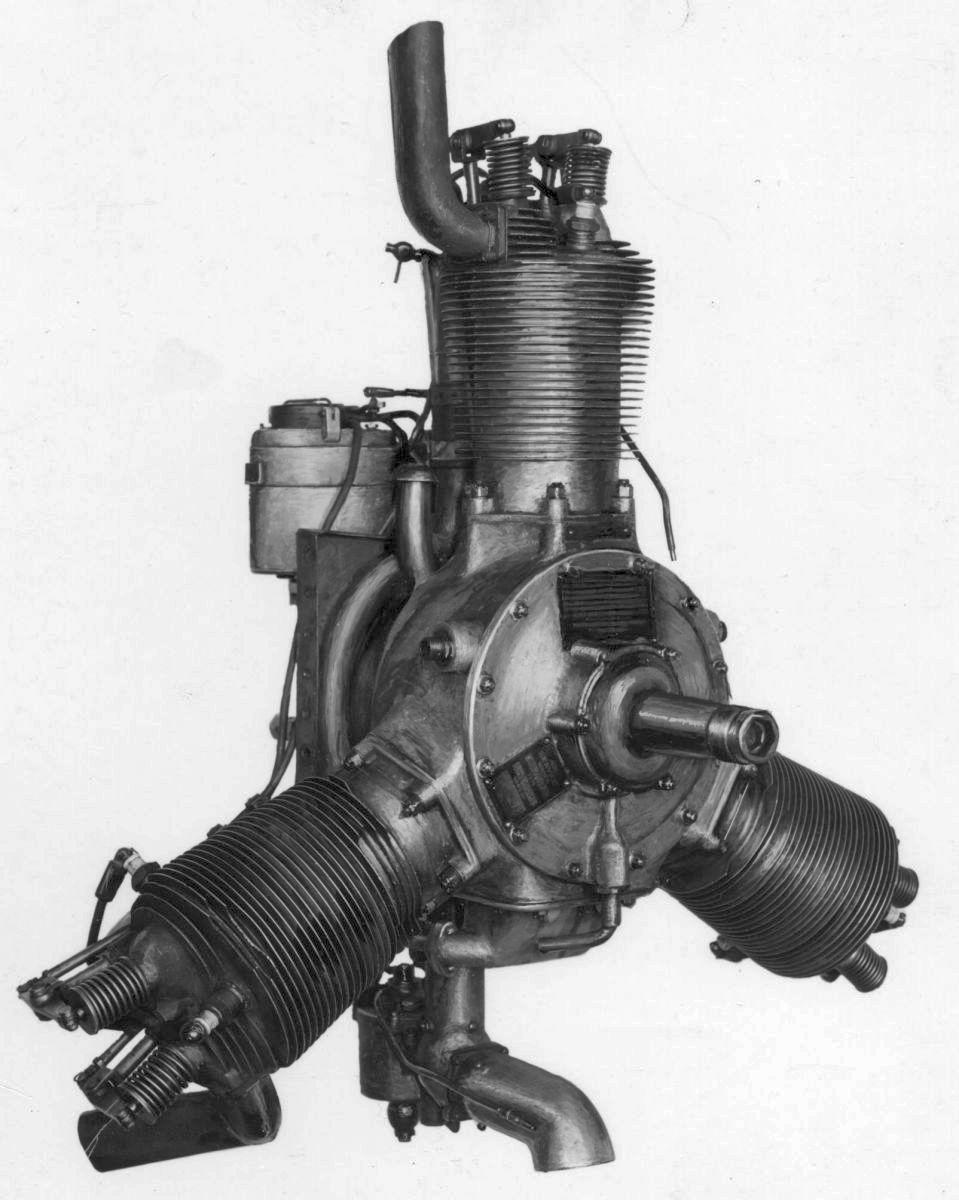
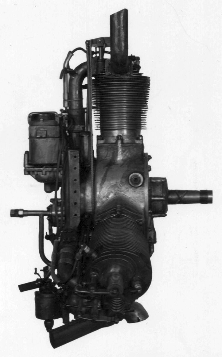
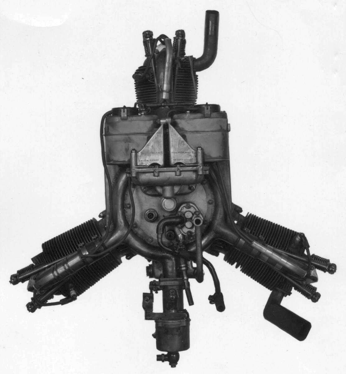
| Lawrance L-4 Equipped with Standard Stromberg M-4 Carburetor | ||
Dynamometer and Propeller Load Tests
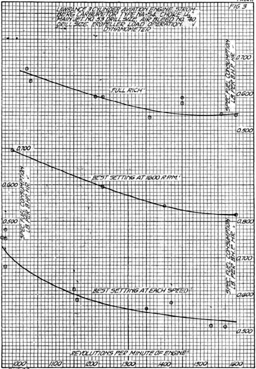
30 Nov 1921 to 7 Dec 1921. A Lawrance L-4 fitted with a NA-S4 carburetor was mounted on the dynamometer and check runs made at 1,600 rpm to determine the proper carburetor setting. Mr. Mock of Stromberg had recommended a 1.375" choke, #49 main jet, #50 air bleed. This combination gave a 0.666 lb/hp/hr fuel consumption at full rich mixture and 0.524 lb/hp/hr at full lean. Several jet combinations were tried with 1.125", 1.250" and 1.375" choke sizes. A 1.250" choke with #54 main jet gave maximum power at a reasonable fuel consumption (52.7 hp, 0.543 lb/hp/hr).
Trouble was encountered during these runs with the oil pump and oil system, and a piston head broke due to overheating. The engine was top-overhauled before the final runs for this setting determination were made.
8 Dec 1921 to 12 Dec 1921. Using settings determined in the initial testing, two full-power propeller load runs were made with the mixture control set to full rich, followed by another propeller load run with the mixture control set to best power at 1,600 rpm. A propeller load run with the mixture control set full rich, was started but not completed, due to irregular and rough operation with back-firing through the carburetor at speeds at or below 1,500 rpm. This trouble was noticed on all propeller load runs. A #53 main jet was substituted and a propeller load run made with mixture control set full rich and best power at each speed. The larger jet did not eliminate the rough operation on propeller load. Propeller load runs at full rich and best power at each speed, including 1,600 rpm, were again made. Some of the rough operation at throttled positions during extended runs were due to carburetor icing.
12 Dec 1921 to 14 Dec 1921. Propeller load runs were made with #40 main jet and #35 air bleed. The results of these runs were very erratic, probably due to carburetor ice formation and the large scale capacity, which were not sensitive enough for small quantity measurements A jacket was installed on the air scoop through which steam could be circulated to slightly heat the induction air and keep the carburetor body warm. A volumetric fuel tank was installed and used in place of the scales for determining fuel consumption.
 |
 |
 |
 |
| Fig. 1 | Fig. 2 | Fig. 3 | Fig. 4 |
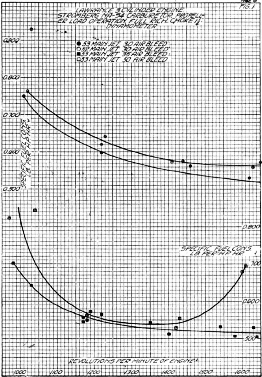
15 Dec 1921 to 17 Dec 1921. Propeller load runs were made with full rich mixture control, a l.250" choke and main jet / air bleed combinations of #53 jet, #35 bleed; #53 jet, #40 bleed; #53 jet, #30 bleed; # 52 jet, #30 bleed; #53 jet, #50 bleed (Figs. 1 and 3). Steam was used in the jacketed air snoop at all speeds below 1,600 rpm (full throttle) and was successful in eliminating the carburetor icing troubles. Check runs were made with and without the use of this heater, which indicated that the horsepower or fuel consumption characteristics were unaffected except where the engine operation was very rough without the heater.
19 Dec 1921 and 20 Dec 1921. The carburetor was fitted with a 1.250" choke, #53 jet and #40 air bleed. It was then subjected to a standard carburetor run. The idle speed with spark full advance was 400 rpm, at full retard 350 rpm. When the throttle was gradually opened from idle speed with propeller loads the engine was rough between 500 and 800 rpm. Slow opening acceleration, however, was good. No information could be obtained on quick throttle opening acceleration due to the dynamometer armature and coupling weights. Two full power runs were made with the mixture control set in the best position at each speed (Fig. 2). Two propeller load runs were made with the mixture control set in the best position at 1,600 rpm and full throttle. Engine operation was rough at 1,400 and 1,200 rpm, cutting out and backfiring through the carburetor. A propeller load run with the mixture control set full rich and "best" at each speed was also made (Fig. 3). A fuel head test as outlined in Engineering Division Report Serial No. 1507 was made, varying the fuel head at the carburetor from 0.4 to 0.8 psi. The engine showed very little power loss at the lower head pressure, but cut out completely when the head became too low for normal operation (Fig. 4). A friction horsepower run at 1,000 to 2,000 rpm completed this dynamometer run series.
Flight Tests
 |
 |
 |
| Fig. 5 | Fig. 6 | Stromberg M-4 |
5 Jan 1922. A Stromberg NA-S4 carburetor was installed on a Lawrance L-4 engine in Verville-Sperry M-1 Messenger airplane, U.S. Army Air Service No. P-225. The carburetor was equipped with a 1.250" choke, #53 main jet and #40 air bleed. Engine ground operation as very rough at practically all speeds other than that at full throttle. A #51 jet improved the operation slightly and increased the maximum speed to 1,610 rpm.
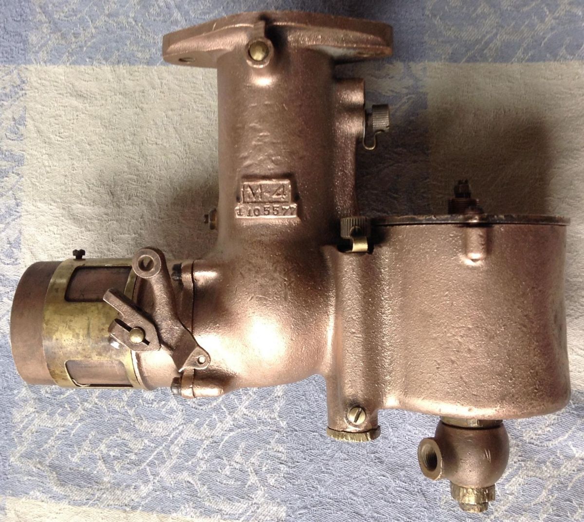
6 Jan 1922 to 9 Jan 1922. As a check on the engine, the original carburetor, a Stromberg M-4, was installed and the engine run on the ground. The operation van fairly smooth over the entire speed range although the engine vibrated badly and the fuel/air mixture distribution was poor at idling speed. A Stromberg NA-S4 carburetor with Stromberg-recommended settings (1.375" choke, #49 main jet, #50 air bleed) was installed. The operation with this setting was also rough with a lean mixture between 1,000 and 1,400 rpm causing back-firing through the carburetor. A new carburetor taken from stock with this setting gave the same results. A #47 main jet smoothed out the lean spot considerably but at the expense of fall throttle fuel economy. The air temperature during these runs was about 30 to 38°F.
12 Jan 1922. A short flight was made with the above setting. It was reported that the full throttle operation was satisfactory but that upon closing the throttle slightly the engine missed badly; this continued over the entire range of cruising speeds.
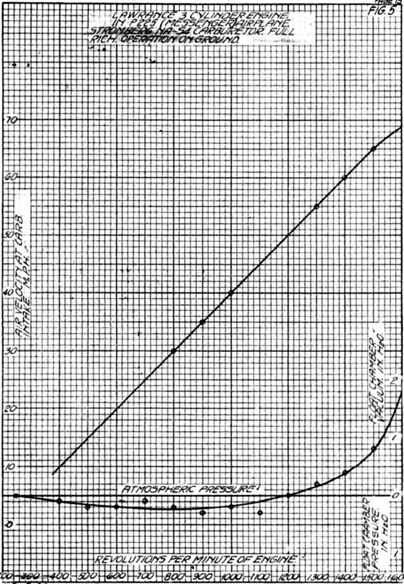
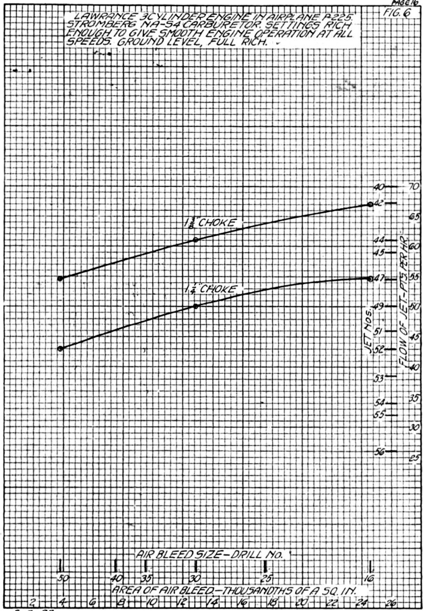
17 Jan 1922. Airplane P-225 was obtained from the Flying Section for the use of the Power Plant Laboratory in testing various carburetor settings in an effort to obtain one that would give smooth operation at all speeds. The float chamber depression and air velocity at the carburetor air intake were determined at various engine speeds on the ground (Fig. 5). Various combinations of choke, air bleed and jet sizes were tested. Two choke sizes,1.250" and 1.375" were used. With each choke size three air bleed sizes (#16, #30 and #50) were used and for each choke / air bleed combination was gradually increased from a size obviously too lean to a size that would just give smooth operation at all speeds when running the engine on the ground (Fig. 6). The discharge nozzle discharge passages were altered by reducing their area by approximately 60% and also by reducing the area of the holes in the standard nozzle add adding a #40 hole in the center of the discharge nozzle top. Neither of these changes made an appreciable improvement in engine operation.
Second Dynamometer Series
 |
 |
 |
 |
 |
| Fig. 1A | Fig. 2A | Fig. 3A | Fig. 4A | Fig. 5A |
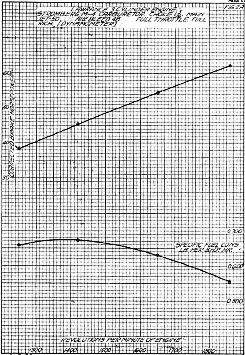
25 Jan 1922 to 26 Jan 1922. A Lawrance L-4 engine was installed on dynamometer No. 5 in order to check the propeller load fuel consumption of the settings determined during the runs with the engine carburetor unit in airplane P-225. A Stromberg M-4 carburetor was fitted to the engine and preliminary runs made, full throttle and propeller load (Figs. lA and 2A).
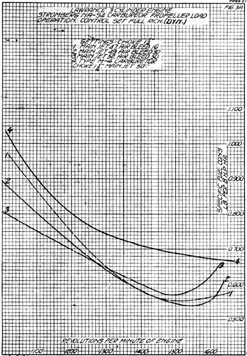
27 Jan 1922 to 2 Feb 1922. Propeller load runs were made with the six satisfactory settings determined by runs with airplane P-225 (Fig. 3A and 4A).
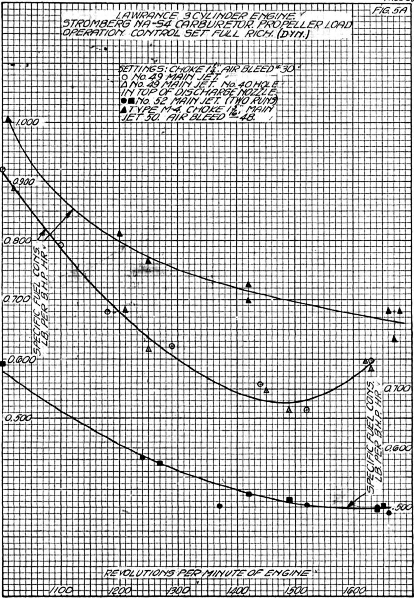
2 Feb 1922. The above results did not check with the results obtained during the first dynamometer run series with the same choke and air bleed sizes but slightly different jet size and different carburetors. Therefore, the original carburetor was installed and propeller load check runs made with 1.250" choke, #30 air bleed and #49 and then #52 main jets. Figure 5A shows the specific fuel consumption curve on propeller load for these two settings. It will be noted that the leaner setting, #52 jet, gives a flat curve from full throttle to 1,400 rpm whereas the richer #49 jet increases the specific consumption an appreciable amount at full throttle and a very small amount at 1,500 rpm, thus producing a hook in the curve's lean range.
A #40 hole was drilled in the top of the discharge nozzle and propeller load runs made using 1.375" choke, #50 air bleed and #47 main jet and also a 1.250" choke, #30 air bleed and #49 main jet. This change to the discharge nozzle showed no appreciable effect on the propeller load specific fuel consumption curve. A blank idle used with a 1.250" choke, #30 air bleed and #49 main jet showed no effect on the propeller load curve from full throttle to 1,300 rpm. A #40 drill was run thru the baffle in the accelerating well and a propeller load run made, 1.250" choke, #30 air bleed, #49 main jet, no effect being noted in the operation or the fuel consumption curve. This completed the run series and the engine was removed from the dynamometer.
8 Feb 1922. From the curves of Figures 3A and 4A, the best setting was selected and a carburetor installed on airplane P-225 with a 1.250" choke, #49 main jet and #30 air bleed. In checking the operation of this setting on the ground it was noted that the carburetor body was split at that part to which the main discharge nozzle was held by the accelerating well.
11 Feb 1922 to 16 Feb 1922. A new carburetor and a longer air scoop was installed. This scoop was approximately 12" long. The operation of this unit on the ground was smooth at all speeds although the distribution was very poor and the vibration excessive at certain speeds. Flights were made by Lt. Macready and Lt. Fairchild, the maximum altitude being 3,000 feet end the air temperature approximately 30°F. Both pilots reported full throttle operation to be satisfactory, but that missing occurred and the engine became very rough as the throttle was closed.
21 Feb 1922. Engine operation on the ground was smooth at all speeds. The float collapsed during this run causing the carburetor to flood. A #47 main jet was put in the carburetor and the engine ground run. This run indicated a rough spot at 800 rpm, apparently due to a rich mixture as it was worse after a prolonged idle that allowed the manifold to load up. A flight was made with this jet and indicated that the rough spot had not been eliminated.
3 Mar 1922. A NA-S4 carburetor with the original 1.250" choke, #49 main jet and a #30 air bleed was installed and fitted with an exhaust type air heater. This heater was one three used on an air heater test conducted on the Lawrance model R-1 9-cylinder engine. Lt. Fairchild flew the P-225 and reported the carburetion good at all speeds. The air temperature was approximately 40°F.
7 Mar 1922 to 9 Mar 1922. A #51 jet was substituted for the #49 main jet and a flight made by Lt. Wade, who reported the maximum rpm to be slightly less than obtained with the larger jet, but the general operation equally was good. The carburetor lower flange was broken around one bolt hole.
22 Mar 1922. Flights to 2,000 feet were made with #49 and #51 jets to note the difference in maximum rpm in level flight. The #51 jet showed 1,700 rpm and the #49 jet 1,690 to 1,720 rpm indicating a difference of 10 rpm, which was a very small difference to detect under flight conditions.
23 Mar 1922. The effect on speed of the two jet sizes was determined on the ground, #51 showing 1,510 rpm and #49, 1,550 rpm. The carburetor flange broke around the two rear bolt holes.
Torque Stand Runs
 |
 |
 |
 |
 |
| Fig. 1B | Fig. 2B | Fig. 3B | Fig. 4B | Fig. 5B |
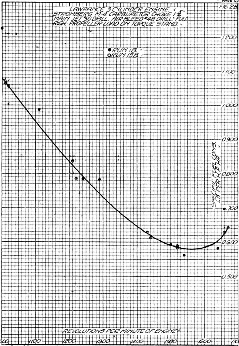
29 Mar 1922, Run 1B. The Lawrence L-4 was installed on the torque stand and a check run made using the Stromberg M-4 carburetor with the standard service setting (1.312" choke, #50 main jet. The cold, damp weather caused considerable trouble due to carburetor ice forming in the manifold just above the throttle, causing the power to drop off at full throttle and speed fluctuations at part throttle operation, The general operation of the engine was very rough and the fuel consumption results inconclusive. The specific fuel consumption on this run were plotted in Figure 2B. This run, however, indicated that the engine was in a fit condition to proceed with the test.
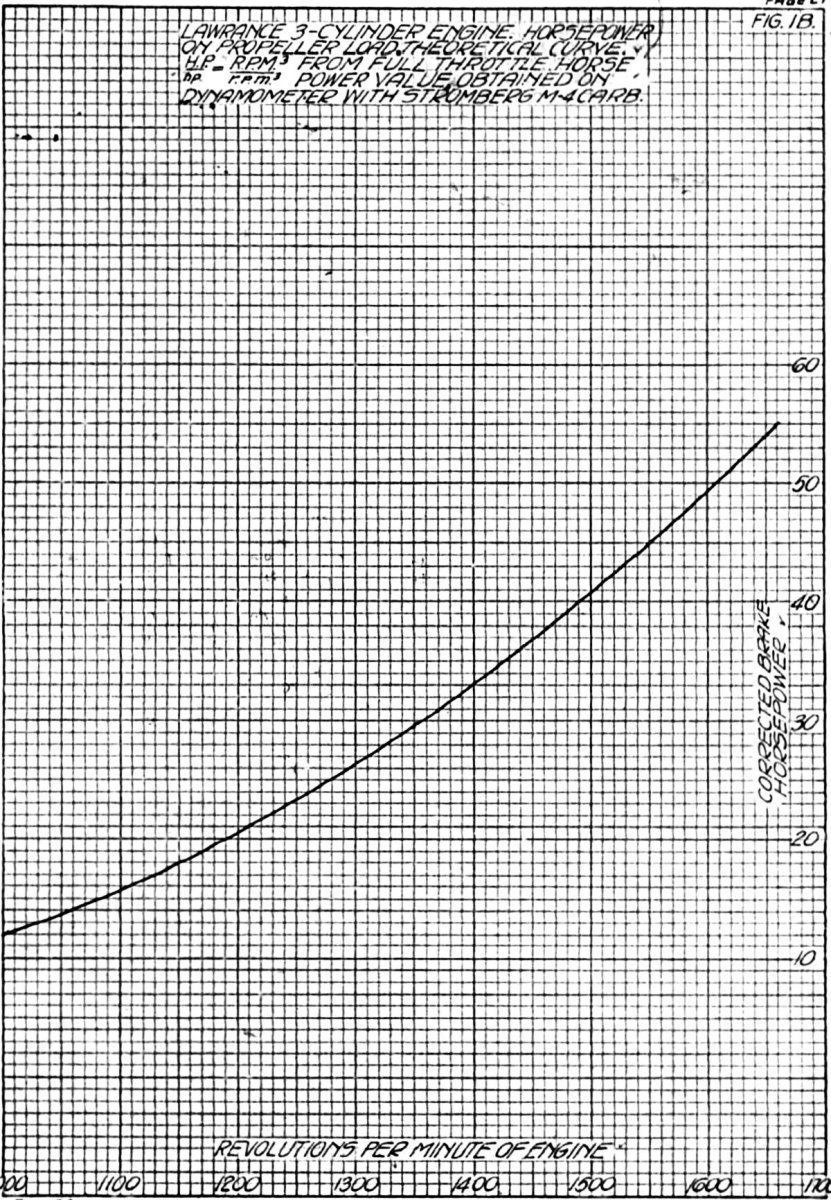
The stand on which this engine was mounted was not of the cradle type so no torque reaction could be measured. The horsepower at full throttle on the torque stand was assumed to be the same as that developed on the dynamometer at the same speed during the full power run. The Stromberg M-4 carburetor with standard setting was used on both runs. A curve of engine rpm versus corrected horsepower (Fig. 1B) was drawn, using the maximum speed on the torque stand and the corresponding horsepower quantity obtained on the dynamometer as a basis and computing the horsepower, assuming it to vary as the cube of the speed, This curve was used for all carburetor settings that were tested.
30 Mar 1922. The Stromberg M-4 carburetor was replaced by the Stromberg NA-S4 and a run started. Excessive carburetor vibration was noted at certain speeds. Upon investigation, a broken manifold proved to be the cause. The break occurred across the back of the manifold between the carburetor flange and the branch tee. The engine was removed for repairs.
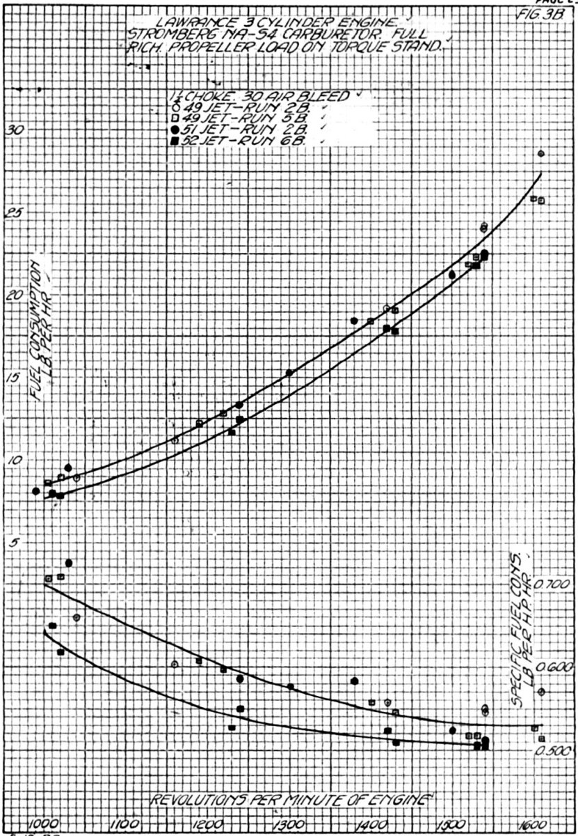
4 Apr 1922, Run 2B. The manifold was welded and the engine put back on the stand with the NA-S4 carburetor, a 1.250" choke, #51 main jet and #30 air bleed. This gave a very flat specific fuel consumption curve on the dynamometer (Fig. 3B). The results did not lie on a smooth curve, erratic readings probably being due to carburetor ice formation, which caused appreciable speed fluctuations. The maximum speed was only 1,640 rpm. as compared to 1,660 rpm obtained with the M-4 carburetor, A #49 jet was put in and a run made. Full throttle rpm was increased to 1,610, Fuel consumptions were plotted in Figure 3B. This setting was the one being used in airplane P-225. The operation in the air was rough at throttled positions without any form of air heater, but was corrected by the use of a heater. The setting showed a low specific consumption at 1,500 rpm, or a "hook" in the curve, on the dynamometer runs.
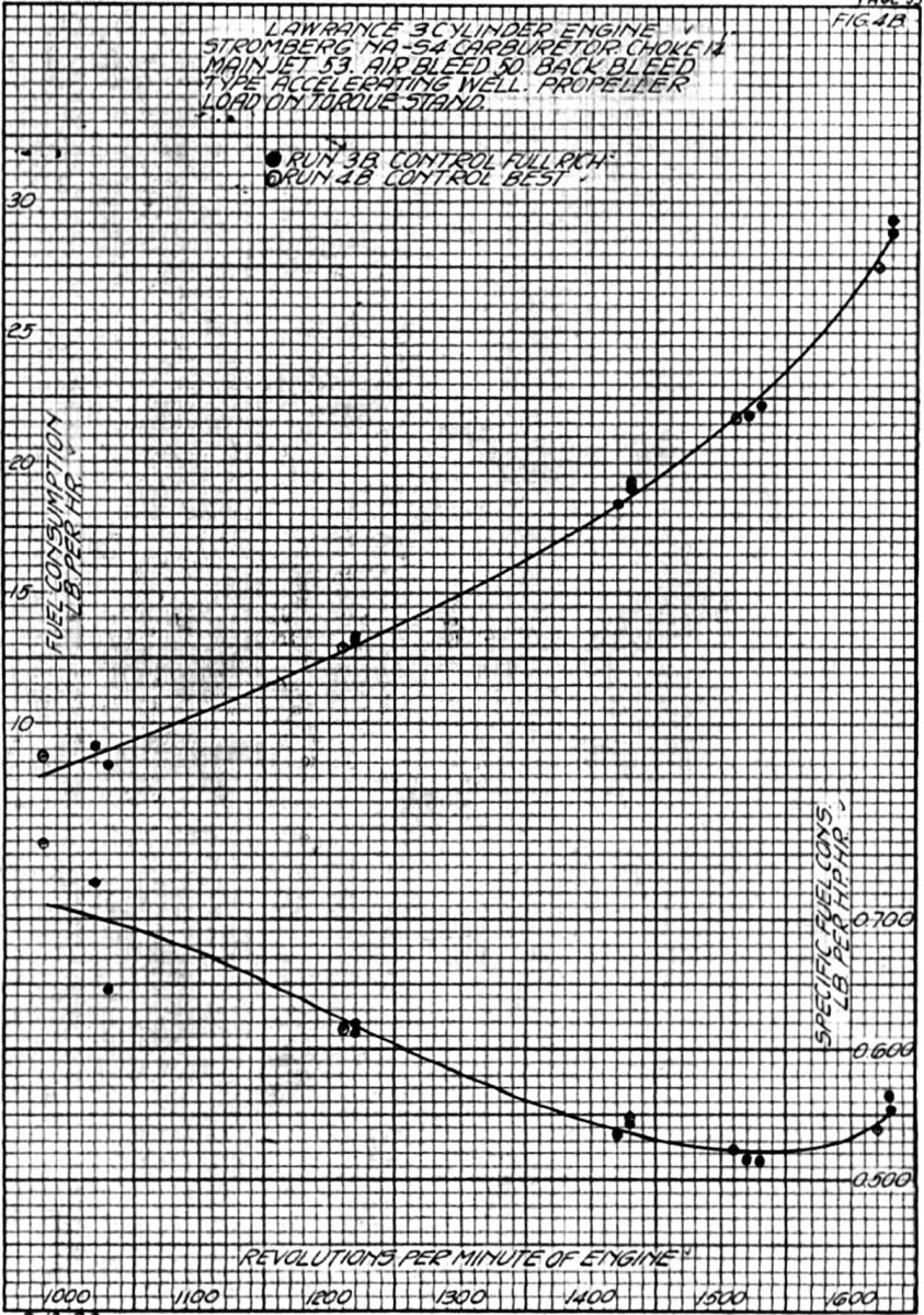
Run 3B. A special accelerating well of the idle back bleed type (Fig. 10) was put in with the standard discharge nozzle, a 1.250" choke, #53 jet and #50 air bleed. This showed more of a "hook" or lean spot at 1,500 rpm in the specific fuel consumption curve than the standard setting.
5 Mar 1922, Run 4B. The restriction just above the main metering orifice on the idle back bleed type of accelerating well was enlarged from a #38 to a #34 drill size. This change had no effect on fuel consumption. The results of runs 3B and 4B are plotted in Figure 4B.
Run 5B. This test 2-B re-run was made with the standard setting then being used for flying—1.250" choke, #49 main jet, #30 air bleed.
Run 6B. A #52 main jet was substituted for the #49 to determine the effect on maximum speed and fuel consumption. This cut the full throttle rpm to 1,540. The results of runs 5B, 6B and 2B are plotted in Figure 3B.
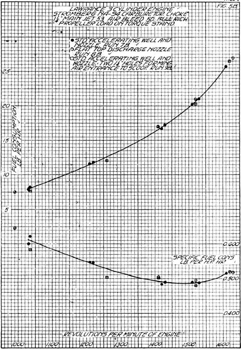
Run 7-B. The settings used in runs 3B and 4B showed the greatest amount of leaning out at approximately 1,500 rpm of any settings tried. A #50 air bleed and a special accelerating well were used during these runs, The smaller #50 air bleed gave a more marked leaning at speeds slightly below normal than the larger sizes tested. Therefore, a ran was made with 1.250" choke, #50 air bleed, and standard accelerating well and discharge nozzle. These results were plotted in Figure 5B, the specific fuel consumption curve having a slight hook. The effect of the idle back bleed accelerating well on fuel consumption may be noted by comparing curves in Figures. 4B and 5B.
 |
 |
| Fig. 10. NA-S4 Idle Back Bleed Type of Accelerating Well and Side Outlet Discharge Nozzle | Fig. 11. Standard NA-S4 Accelerating Well and Discharge Nozzle |
Run 8B. A special flat top discharge (Fig. 11) nozzle, with 4 holes drilled toward the center at a 45° angle with the center line, was substituted for the standard nozzle and a run made with the same #53 jet and #50 air bleed used during run 7-B, The results were plotted in Figure 5B and indicate that this nozzle has no appreciable effect on the fuel flow characteristics.
16 Apr 1922. Run 9B. The standard discharge nozzle, 1.250" choke, #53 main jet, and #50 air bleed were used for this run. In order to determine whether an expansion chamber below the main jet would have any effect on dampening the pulsation at the jet, a restriction was placed over the air scoop mouth. Air entered the scoop through two 1.250" diameter openings 1-1/4 inches in diameter allowed air to enter the scoop. The results of this run are plotted in Figure 5B. The restriction had no apparent effect on power or fuel consumption.
 |
 |
 |
 |
| Fig. 6B | Fig. 7B | Fig. 8B | Fig. 9B |
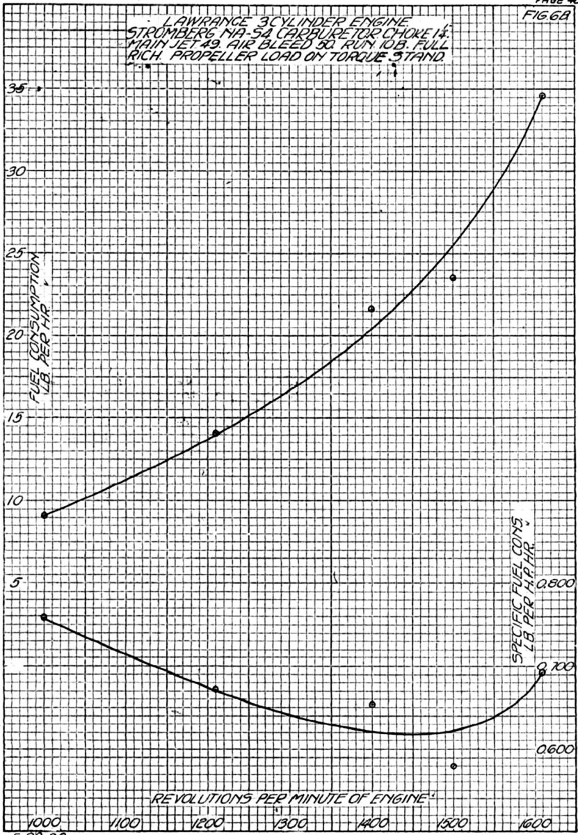
Run 10B. Dynamometer runs indicated that as the jet size was increased, other factors remaining constant, the amount of "hook" of the specific fuel consumption curve increased, the consumption at full throttle increasing appreciably, while that at about 1,500 rpm remained more nearly constant. To verify this on the torque stand, a run was made with a 1.250" choke, #49 main jet and #50 air bleed. The results are plotted in Figure 6B. Comparing the fuel flow curves in Figures 5B and 6B with #53 and #49 jets respectively, it will be noted that the larger jet increased fuel flow by about 9 lb/hr at fall throttle and only 3/8 lb/hr at 1,500 rpm and 4.2 1b/hr at 1,400 rpm; this indicating a lean spot at approximately 1,500 rpm. The fact that the points do not fall on the curve at 1,400 and 1,500 rpm was not entirely due to experimental error as this tendency was noticeable with practically all the settings tested.
7 Apr 1922. Run 11B. A run was made with the idle back bleed accelerating well, 1.250" choke, #51 jet, #40 air bleed, and an idle discharge nozzle with a #60 restriction. The results are plotted in Figure 7B. This accelerating well was designed to bleed air down through the idle passages at full throttle, The use of #60 instead of a #52 passage in the idle discharge nozzle had very little effect on fuel consumption at fall throttle. Compare the results with this Figure 7B setting, with those of practically the same Figure 4B setting. The smaller passage for the idle discharge was effective, however, in increasing the effectiveness of the air bleed used for adjusting the idling mixture proportions and in changing the form of the specific fuel consumption curve.
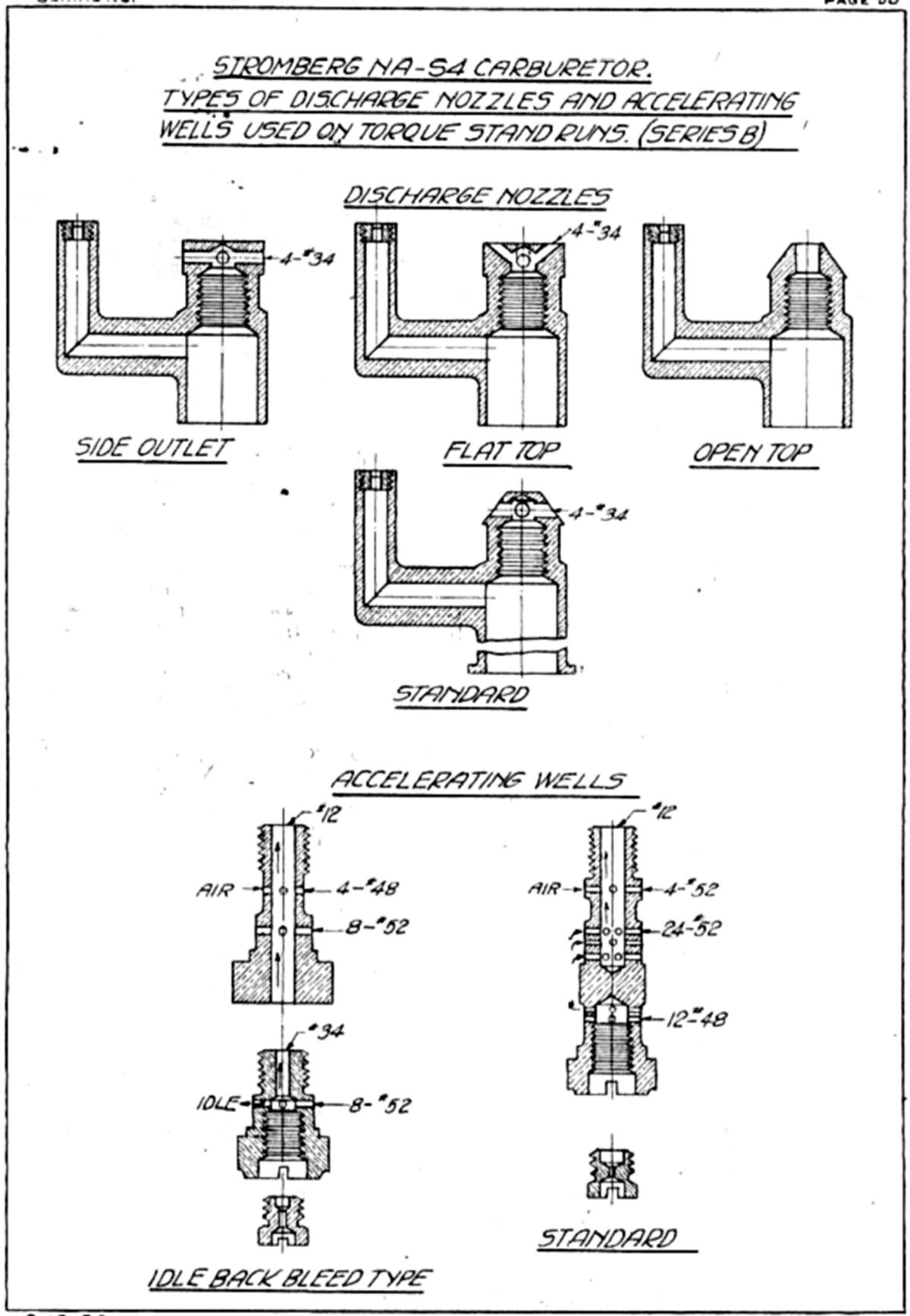 |
| Fig. 68. NA-S4 Discharge Nozzles and Accelerating Wells used on Torque Stand Runs |
Run 12B. An open top discharge nozzle (Fig. 68) was substituted for the standard nozzle; all other carburetor settings remained the same. This nozzle type increased the full throttle fuel consumption slightly, but at 1,500 rpm it remained practically the same. This run indicated that the open top type of nozzle gave a slightly a different hook than the standard, the pulsations on the open top having some effect in retarding the flow at speeds below 1,500 rpm.
8 Apr 1922. Run 13B. A side outlet discharge nozzle (Fig. 68) was substituted for the open top nozzle with no other changes made. This arrangement gave a lean mixture at full throttle and a very flat specific fuel consumption curve (See Fig. 7B). A larger #49 jet, gave a richer mixture at full throttle only, indicating that the flat curve was brought about by a lean mixture over the entire range rather than by any characteristics of the discharge nozzle. (See Fig. 7B)
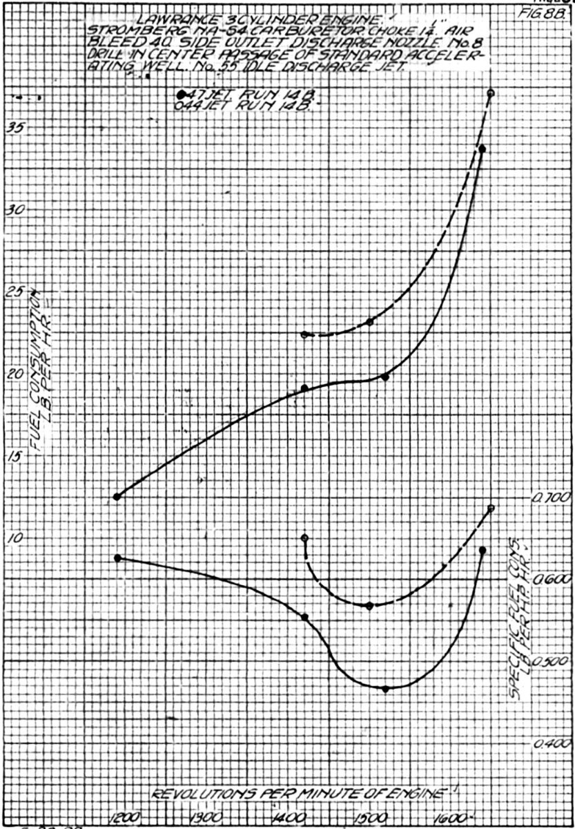
10 Apr 1922. Run 14B. A run wan made with a side outlet discharge nozzle, 1.250" choke, #40 air bleed, #55 idle discharge restriction, a standard accelerating well with the #12 central passage drilled out to #8, and #47 and then #44 min jets. The results were plotted in Figure 8B. Each jet gave a rich mixture at full throttle and the characteristic lean spot at 1,500 rpm, indicating again that the side outlet discharge nozzle did not appreciably change the fuel consumption on propeller load.
Run 15B. A Stromberg M-4 carburetor was again fitted to the engine with the standard 1.312" choke., #50 main jet, and #48 air bleed settings. A check of run 1B was made. Those results were plotted in Figure 2B.
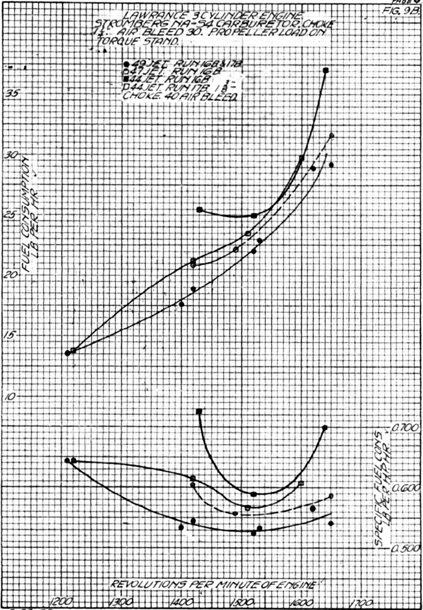
Run 16B. The NA-S4 carburetor was placed on the engine with a standard discharge nozzle and #30 air bleed; other settings remaining the same as on run 14B. Runs were then made with #49, #47 and #44 main jets. These results, plotted in Figure 9B, show a smooth flat curve for the leanest setting, (#49) and an increasing amount of "hook" as the jet size was increased.
11 Apr 1922. Run 17B. A 1.375" choke was substituted for the smaller size and a run made with a #44 main jet; no other setting changes were made. This setting gave no more full-throttle rpm and had the same fuel consumption as the 1.250" choke. A final check was made with a 1.250" choke and #49 main jet. These results were all plotted in Figure 9B. A broken carburetor flange was discovered at the end of this run and the test discontinued.
This torque stand run series indicates very plainly that a flat smooth specific fuel consumption curve was obtained with a lean setting and that with larger jets, the specific fuel consumption remains low, indicating a lean mixture at a speed of approximately 1,500 rpm. This was probably due to a critical period of air flow pulsations, and was not affected by any type of accelerating well or discharge nozzle tested.
Final Carburetor Test Chamber Runs and Flight Tests
 |
 |
|
| Fig. 1C | Fig. 2C | Fig. 3C |
17 May 1922. A NA-S4 carburetor was drawn from stock, checked and placed in the carburetor test chamber. It was set for typical flight use: 1.250" choke, #49 man jet and #30 air bleed.
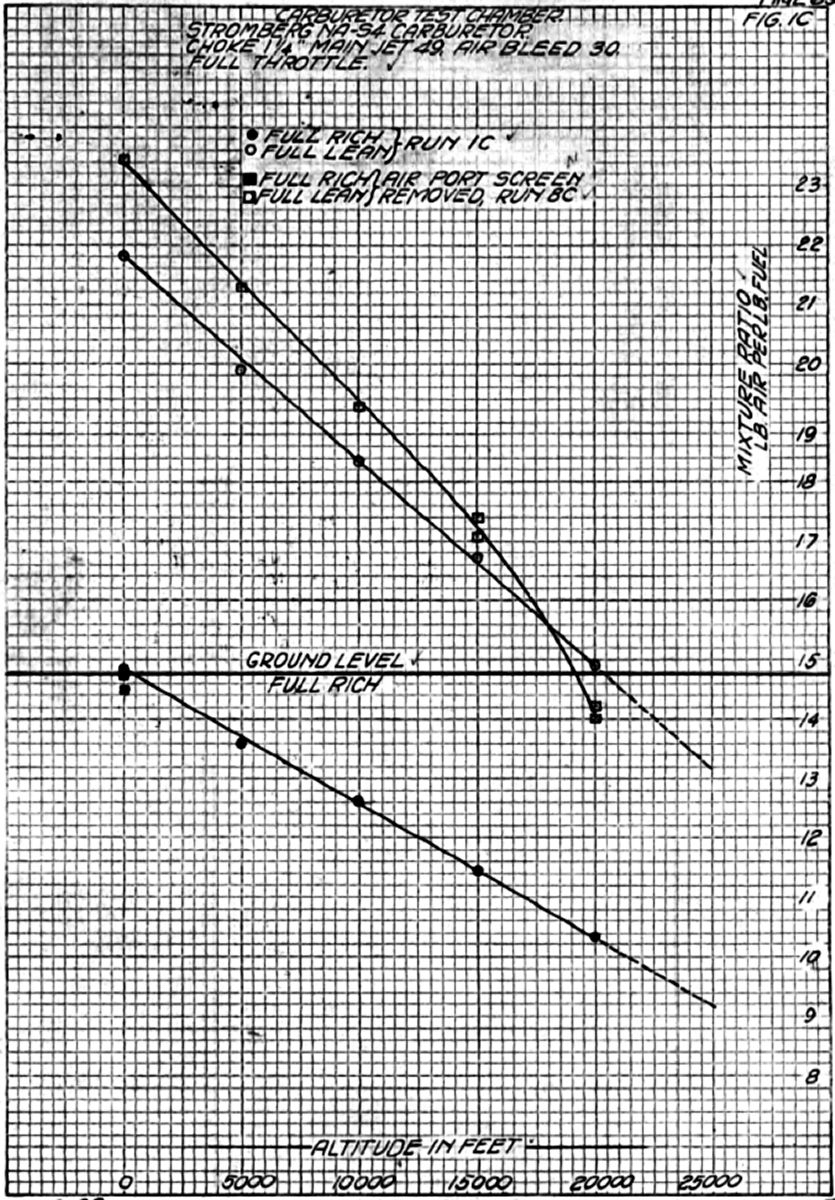
Run 1C. The mixture ratio was determined for full throttle operation at each 5,000-foot altitude increment from ground level to 20,000 feet (this was called an altitude run) with the mixture control set full rich and also full lean. Figure 1C shows the plotted results of these data indicating that the mixture control was effective in producing ground level mixture at 20,000 feet. The mixture enrichment at 20,000 feet compared to ground level mixture ratio was 43.5%.
Run 2C. The mixture control valve characteristics were determined at ground level, full throttle, by measuring the mixture ratio at various control valve positions using 10° increments of angular travel or opening from 0° (closed) to 65° (full open).
Run 3C. A similar run was made at 10,000 feet altitude. The results of runs 2C and 3C were shown in Figure 2C.
Run 4C. A propeller load run was made at ground level, full rich (see Fig. 3C). This showed no lean range as occurred during dynamometer, torque stand and flight tests, which seemed to confirm the theory that this leanness was due to the effect of manifold pulsations resonating with carburetor air and fuel flow.
1 Jun 1922. Runs 5C and 6C. Propeller load runs were made at ground level with the control in the full lean position. The results of these runs, plotted in Figure 3C, indicated that the mixture richens appreciably as the speed decreased, this effect being greater when the control was used.
Run 7C. A check or run 4C was made. The results were plotted in Figure 3C.
6 Jun 1922. Run 8C. The screen around the carburetor barrel, through which the auxiliary air for mixture control passed, was removed and an altitude run, ground level to 20,000 feet, was made. The screen's effect at ground level was small but significant and decreased with altitude (see Fig. 1C).
12 Jun 1922. Run 9C. Propeller load runs were made at 5,000 feet altitude with the mixture control set at full throttle to obtain ground level mixture. Two runs were made, one with the air port screen removed and one with installed. At this altitude an auxiliary air port throttle opening of 12° was required and the effect of the screen small. The average results of the two runs were plotted in Figure 3C.
13 Jun 1922. Run 10C. A propeller load run was made at 20,000 feet with the mixture control set full lean. The test chamber pump capacity was too low to maintain the decreased density in the chamber at nominal speeds of less than 1,400 rpm. The results were plotted in Figure 3C.
Run 11C. A propeller load run was made at 15,000 feet with the mixture control set at full throttle to give ground level mixture ratio, 40° opening being required (see Fig. 3C). Run 12C. A propeller load run was made at 10,000 feet with the mixture control set at 27° opening, which gave approximately ground level mixture ratio at full throttle (see Fig. 3C).
20 and 21 Jun 1922. Run 13C. Two runs were made at 20,000 feet altitude with full throttle readings taken for every l0° of mixture control travel. These runs were similar to runs 2Cand 3C. The results were plotted in Figure 2C.
 |
 |
 |
| Fig. 72 | Fig. 73 | Fig. 74 |
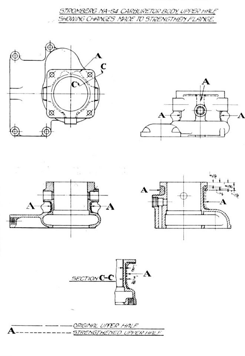
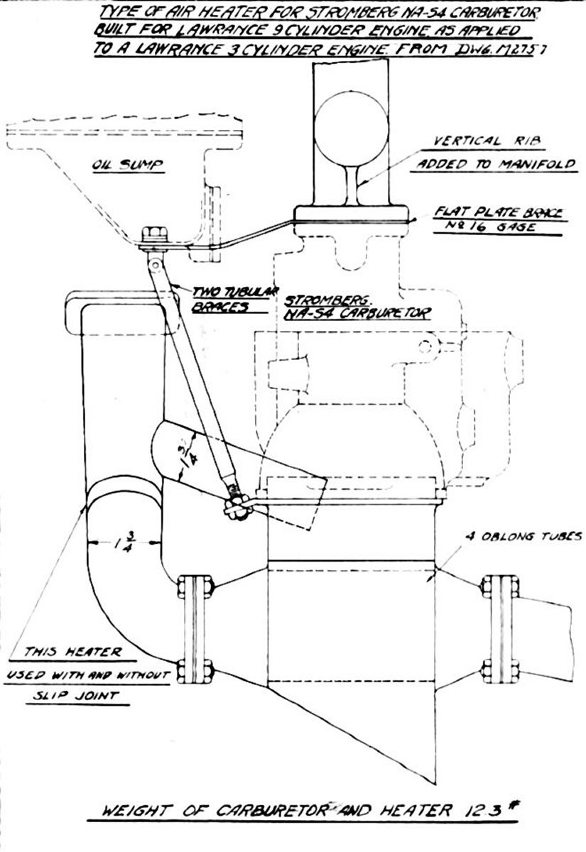
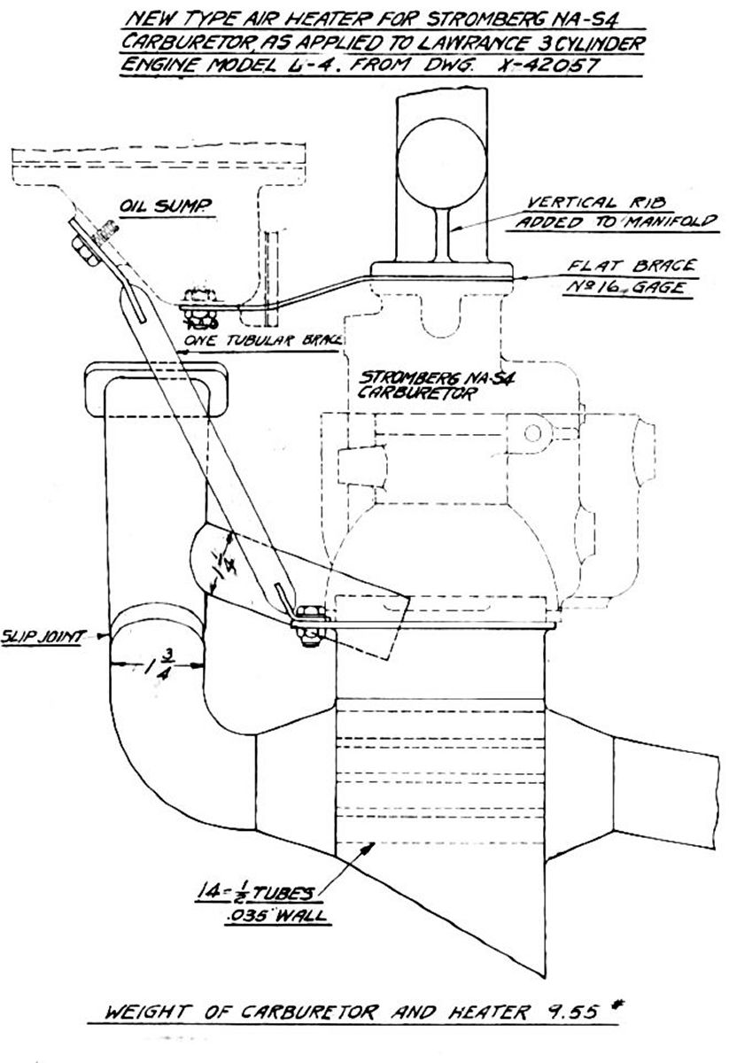
8 Aug 1922 - Airplane P-223. A Stromberg NA-S4 carburetor with a 1.375" choke, #49 main jet and #30 air bleed had been installed on P-223 since 21 Jun 1922 and was being used under service conditions. This installation also included an old type air heater with braces from the heater flange to the oil pump and one from the manifold flange to the oil sump. This carburetor and air heater were removed and a new carburetor with a new reinforced upper half (Fig. 72 ), 1.250" choke, #49 main jet, #30 air bleed, and a new type of air heater (Figs. 73 and74) fitted to the engine. The Flying Section was asked to use this snip and the carburetor installation as much as possible under service conditions and to notify the Power Plant Laboratory of any failures.
12 Aug 1922 – Airplane P-225. A new engine was installed that included a NA-S4 carburetor with a 1.250" choke, #49 main jet, #30 air bleed, and an old type air heater. Flights were made with this installation and the operation reported as satisfactory.
15 Aug 1922. The new type of accelerating well was installed in the carburetor on airplane P-225. This wall was designed to overcome the effect of intake manifold pulsations on the fuel consumption curve during propeller load operation. Flights were made with 1.250" choke, #49 main jet and #30 air bleed; no air heater was used. The operation was reported as being satisfactory at throttled speeds as well as at full throttle.
17 August 1922. The main jet size was reduced from #49 to #51 and flight tests made. Operation was reported to be satisfactory although the mixture was lean enough to be immediately affected by any mixture control lever movement.
25 Aug 1922. The following memorandum was written to the Flight Test Section regarding flight test being conducted on airplane P-225.
Flight Test Section
E.O. 519-16 – Test of NA-S4 Carburetors
- Regarding verbal conversation with Lt. Wade pertaining to the above Expenditure Order number, the Divisional planning Section has been consulted and the necessary steps have been taken to have this number reopened with the Flight Section.
- A standard NA-S4 carburetor with standard setting was first applied to the M-1 Messenger airplane P-225. This carburetor had the air heater stove attached and its performance on flight test was verbally reported as satisfactory. The carburetor was then removed and a new type of accelerating well tube applied. When remounted the air heater stove was omitted. A flight was made with this arrangement and the performance verbally reported an satisfactory. The main metering jet size in the carburetor was then reduced to the minimum possible consistent with maximum power and a flight made.
- The following information was desired from the pilot who flew this airplane:
- Remarks on engine operation at full throttle and at throttle speeds with the standard setting and air heater stove. Also any remarks thought necessary pertaining to idling.
- The same information as above on the carburetor with the new type well tube without the air heater stove and rich setting. Also the effect of use of mixture control.
- Same as above on the new type well tube without air heater stove and lean setting.
- Also any general remarks that the pilot might think pertinent to this test.
- Right at present no more specific test flights are required but it is desired that this airplane be given as much incidental flying as possible and a general record kept of the carburetor operation and any complaints that may arise. It is desired, if possible, to improve this carburetor so that it will operate under all weather conditions without the air heater stove. From present indications it can be done under these weather conditions, the final test, however, will be during the severe winter weather.
L. S. HOBBS, Test Engineer
C/C
Mr. Bussey
Mr. Bottles
Cost Dept.
[Note: The test engineer who signed the above memorandum was Leonard S. Hobbs, who would later become Pratt & Whitney Aircraft's chief engineer.]
30 Aug 1922. The following memorandum was received from the Flying Section giving the results of flight tests on airplane P-225. These tests and records were made by Mr. Art Smith, Test Pilot.
Dynamometer Laboratory — Test of NA-S4 Carburetor on P-225
- In test flights with the Messenger airplane P-225, having an air heater stove attached to carburetor, it was found that the engine ran smoothly and satisfactorily at all throttle settings.
- With air heater stove removed and new-type well tube installed, there was no change in the satisfactory engine performance at different throttle settings. There was, though, an increase of about 100 rpm at full open throttle setting.
- As last flown with mixture leaned out by size of jet used, it was found that no altitude control could be used without causing skipping at altitudes up to 2000 feet. No tests were made above this altitude.
- With the new type well tube all throttle performances was quite satisfactory without the air heater stove, while the flying qualities were much improved by the additional 100 rpm.
H.R. Harris, 1st Lt. A.S., Chief Flying Section
Copy to Mr. L.S.Hobbs.
 |
| Fig. 79 |
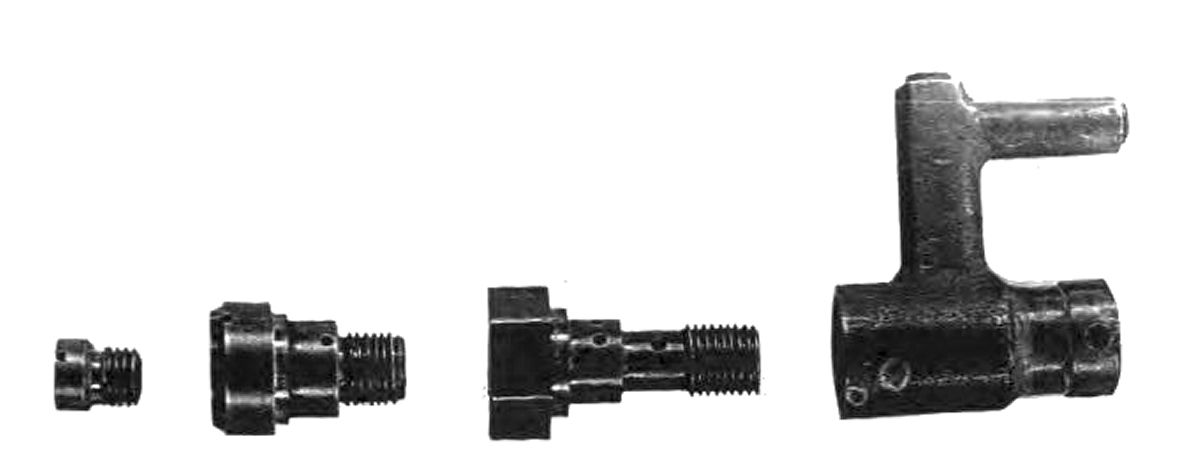
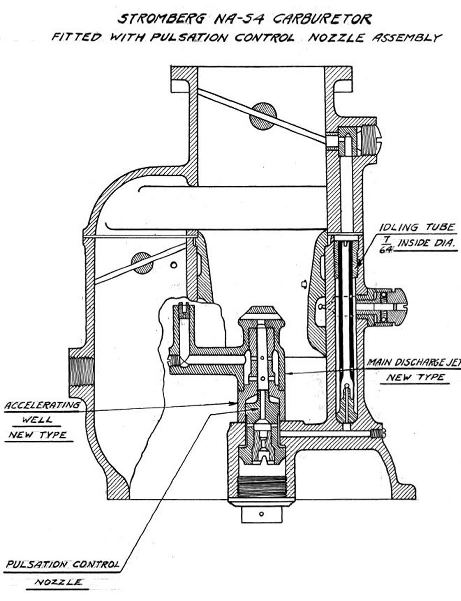
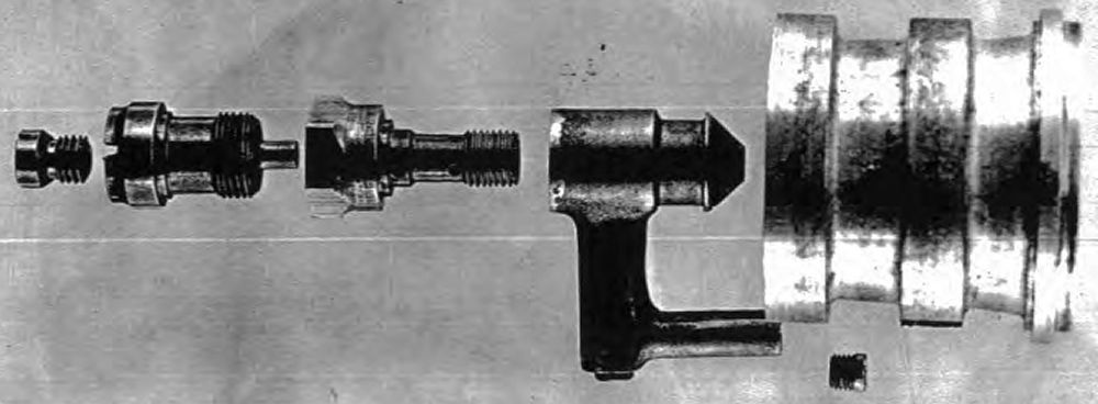
Figure 79 shows the construction of the new discharge jet furnished by Stromberg Motor Devices Company and used in the flight tests discussed in the foregoing paragraphs. In a letter of 19 Aug 1922, written by Stromberg Motor Devices Company to this Division, the theory of this type of discharge jet was given as follows:
"The principle of this now type of discharge jet structure was briefly as follows: at wide open throttle the pulsation or intermittent suction tend to make the mixture richer than at partial closings of the throttle where the suction was more nearly uniform. To offset this effect, we have taken advantage of the fact that at wide open throttle there was a reverse of flow through the idling metering nozzle, air going downward through the nozzle and over into the main discharge jet passage. In order that the small amount or air thus flowing into the discharge jet passage may exert a definitely leaning out effect upon the mixture, the fuel passage was restricted for a short distance beyond where this air enters, the leaning out effect being proportional to the restriction under conditions of this kind. This restricted passage was contained in what we have called the pulsation control nozzle and we estimate that a #25 drill passage in the pulsation control nozzle will give about the same mixture proportion as has been obtained with the previous type of accelerating well tube. We are sending you #30 and #34 pulsation control nozzles as we believe these will give all the range of action that will be safe to use. We find that if this action was carried to extremes, it results in the mixture being controlled by the idling adjustment up to the equivalent of perhaps 1,400 rpm of the motor, propeller load.
In fitting these new parts in the carburetor, we would caution you to be very careful that the idling tube seats securely on the spherical surface at its bottom, also that the pulsation control nozzle draws up absolutely tight in the main discharge jet thread. Leaks at either of these points will lean out the mixture to a surprising extent due to the frictional effect of the small passage in the pulsation control nozzle."
 |
| NA-S4 Metering System with Pulsation Control Nozzle |
31 Aug 1922. At the request of the office of the Chief Engineer, flight tests were made with airplane P-223 to determine the characteristics of the new type of air heater and compare the general operation of the carburetor with that obtained with the old type of air heater. This work was done under E.O. 416-21. A flight was made with the new air heater and one with the standard short air scoop. Weather conditions were very favorable for operation without any air heater, the average air temperature being approximately 85°F. The engine operation was satisfactory over the entire range of speeds either with or without the air heater, although the heater cut the maximum revolutions approximately 50 rpm. These tests were covered by a memorandum report issued under E.O. 416-21.
Send mail to
![]() with questions or comments about this web site.
with questions or comments about this web site.
![]()