


Stromberg NA-S4 Development
Part 4: Testing on the Lawrance J-1
Compiled by Kimble D. McCutcheon
Published 17 Jun 2024
| This phase of the Stromberg NA-S4 carburetor development was undertaken to investigate the metering and carburetion characteristics on the Lawrance 9-cylinder engine, Model J-1. The carburetors showed the same general metering characteristics and defects in flight on the 9-cylinder Lawrance Model R-1 as on the 3-cylinder L-4, but not to such a marked degree. |
| Part 1: Description | Part 3. The Fixes |
| Part 2. Testing on the Lawrance L-4 | Part 4. Testing on the Lawrance J-1 |
|
|
|
|
|
|
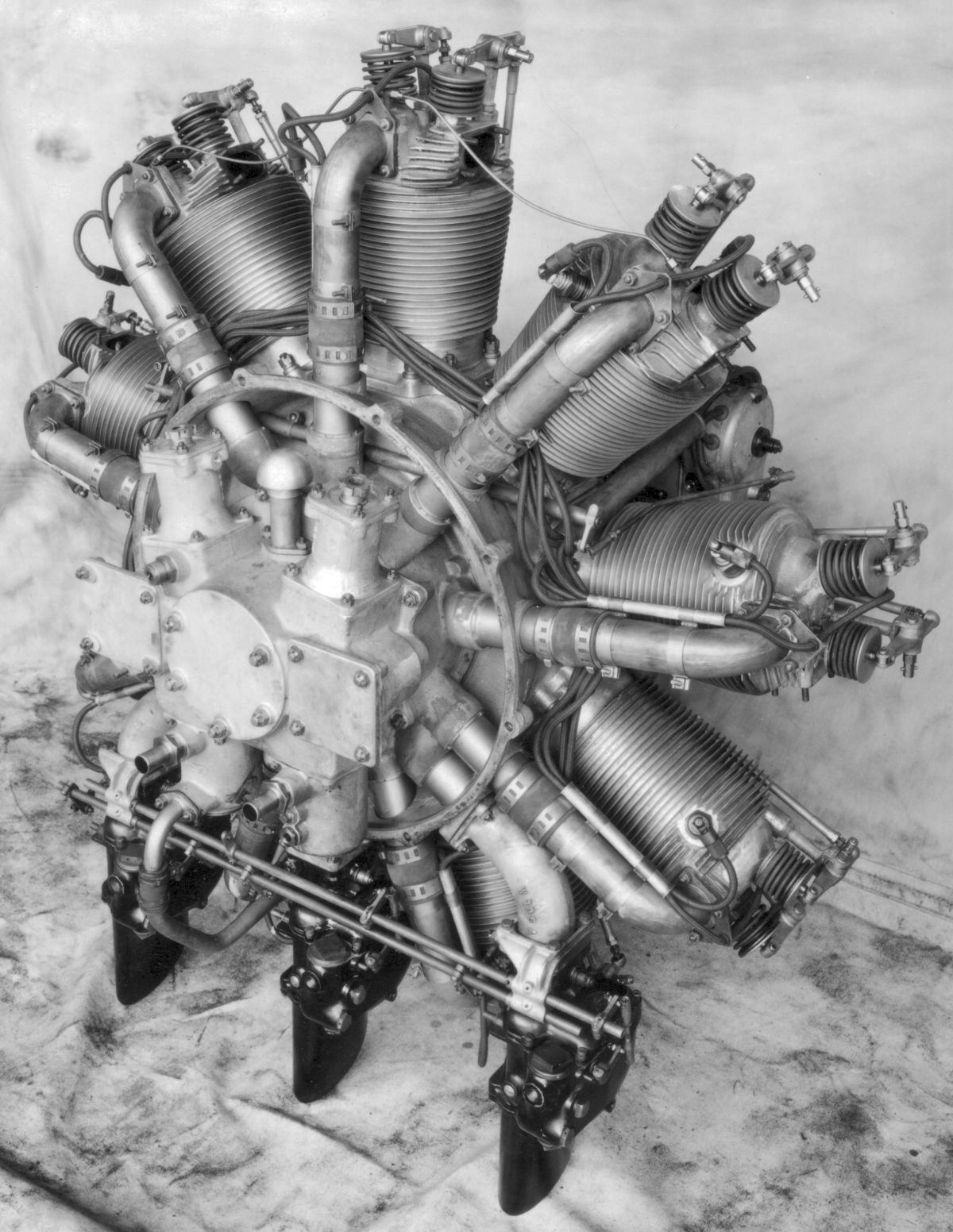
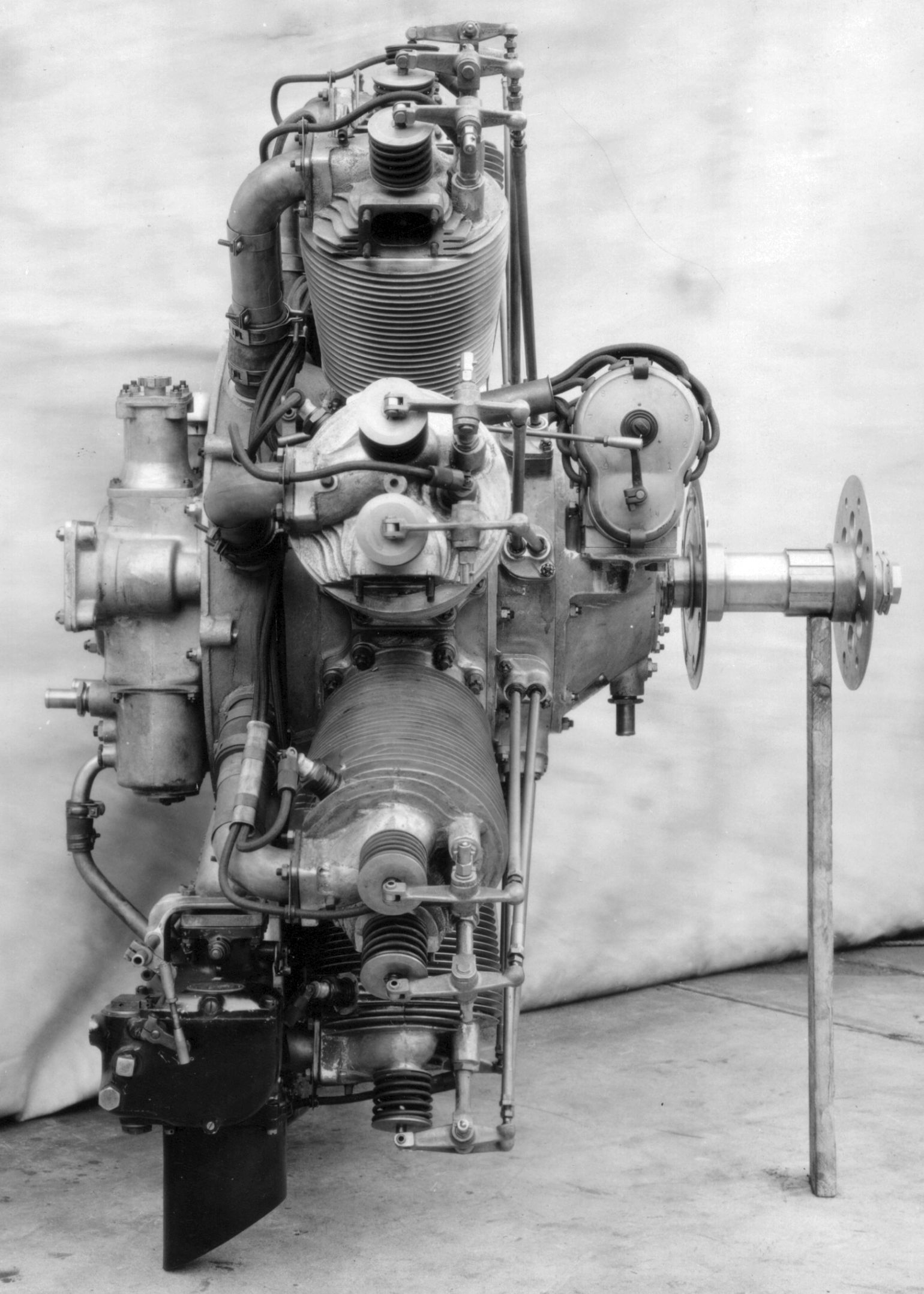
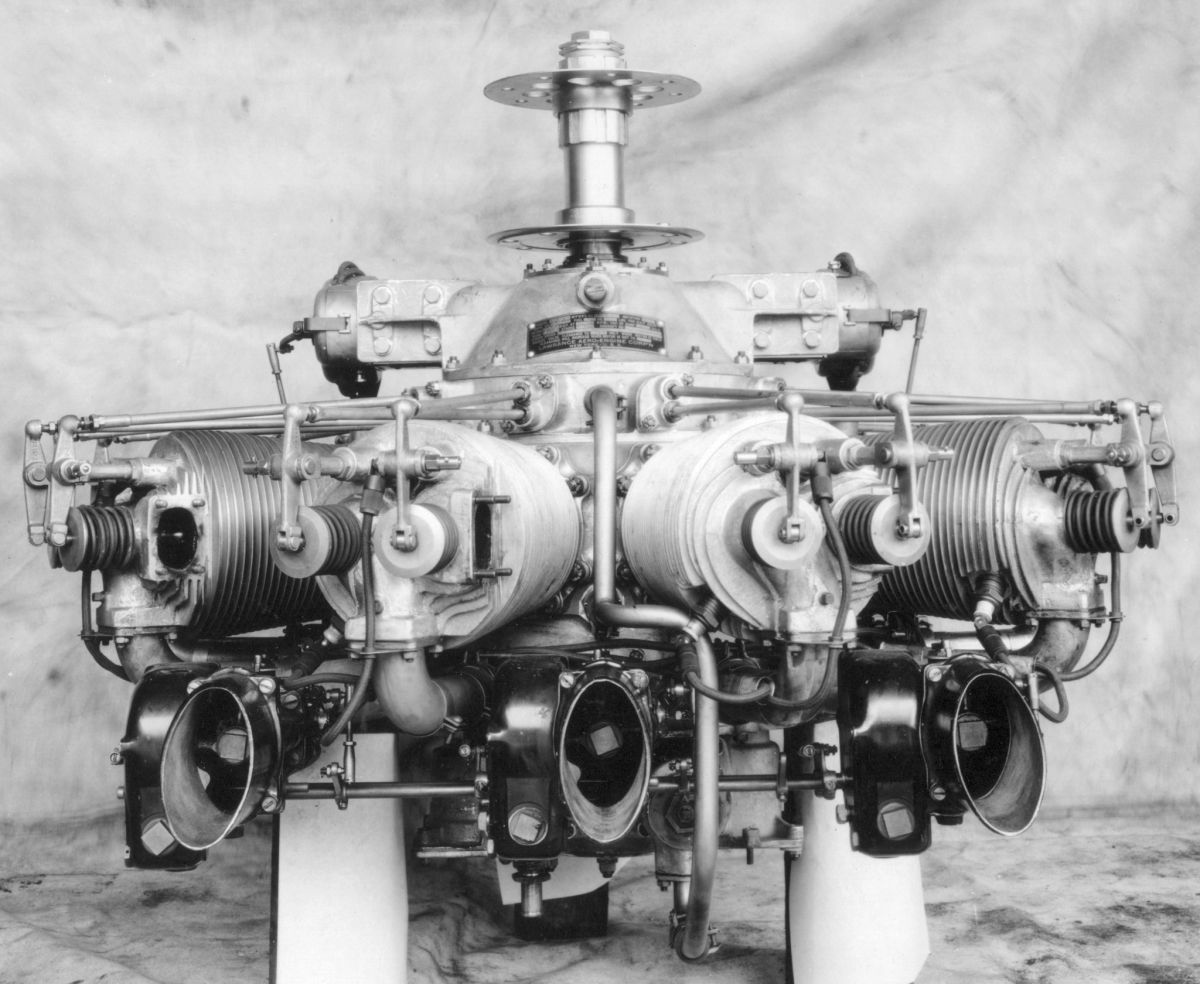
| Walk Around | Bottom View | ||||
Lawrance 9-Cylinder Model J-1 Dynamometer Runs
Several 9-cylinder Lawrence engines were being used by the Navy at Anacostia and by the Engineering Division. The difficulty of a lean and therefore rough spot at approximately 1,500 rpm was overcome on these engines by using a large jet with the resulting high fuel consumption at full throttle operation, instead of by the addition of an air heater as used on the 3-cylinder L-4 engines by the Engineering Division.
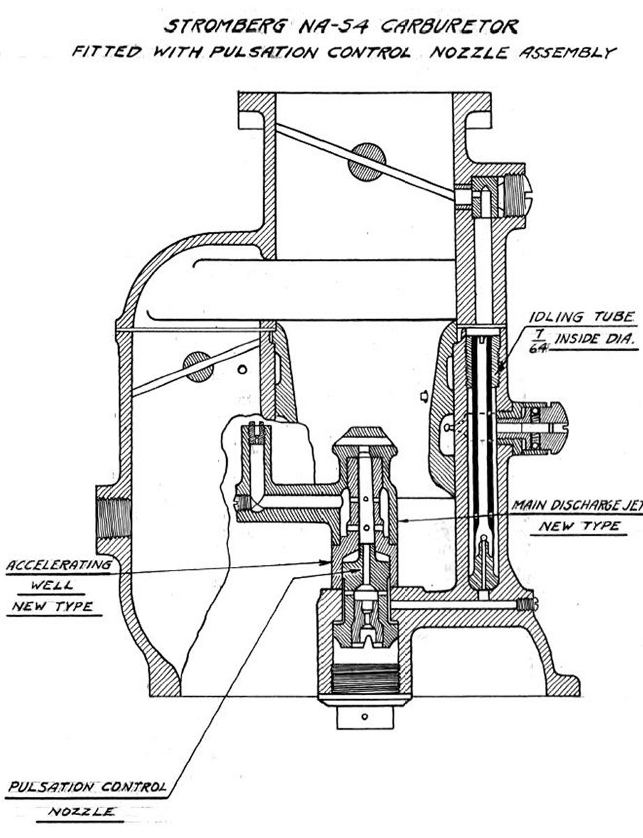 |
| Fig. 79 |
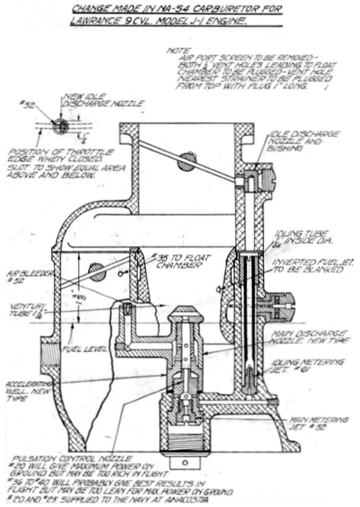
Several propeller load runs with various size air bleeds in standard accelerating wells as was done on the L-4s was planned, followed by these same air bleed sizes and new type of pulsation control nozzle (Fig. 79) furnished by Stromberg Motor Devices Company.
8 Sep 1922. Run 1D. A Lawrance J-1 was installed on the dynamometer. A check run was made at 1,800 rpm, full rich mixture. The carburetor setting comprised 1.437" chokes, #45 main jets and #50 air bleeds. A fuel mixture consisting of 20% benzol and 80% domestic aviation gasoline (hereinafter D.A.G.) , W.E. specification No. 2-40 having a 0.740 specific gravity at 80°F, was used for this and future runs. Maximum power at 1,840 rpm, full throttle, was 191.4 hp as compared with 215.8 hp corrected at 1,830 rpm obtained on a previous test.
9 Sep 1922. Run 2D. The standard-issue A.C. spark plugs were replaced by Champion Toledo plugs as they did not foul as readily as the A.C. plugs. The check run of 8 September was repeated, the results being practically the same. The power output was not decreased by setting the mixture control to the full lean position. At the completion of two runs the power was noted to have dropped off. The engine was allowed to cool and the runs repeated at 1,800 rpm, producing 180 hp compared to 195 hp previously obtained. A #47 main jet was installed in the three carburetors and check runs made at full rich and full lean mixture. The power output was still very low at 173 corrected hp.
11 Sep 1922. Run 3D. The air temperature being much lower than on 9 September, a check run was made to note the increase in power if any; the power was still low.
Run 4D. This engine had been given a top overhaul prior to installation on the dynamometer for this test. The valve timing, magneto timing and valve clearances were checked and set to the values used before top overhaul. The magneto timing was changed an appreciable amount, being set at 33° BTC for the head plug and 29° BTC for the rear plug. This brought the corrected horsepower to approximately 200 hp, which was still somewhat lower than that obtained on previous runs, but as the difference was not excessive a propeller load ran was started but not completed due to lack of time.
12 Sep 1922. Run 5D. A propeller load run was made, with readings taken every 200 rpm from 1,800 rpm to 1,000 rpm. This data showed a very high specific fuel consumption at 1,600 rpm compared with that at other speeds. To check this point on the specific fuel consumption curve a propeller load run was made 1,800 rpm to 1,400 rpm with readings taken at every 100 rpm. The load and speed varied considerably at 1,600 rpm making it difficult to obtain a stable throttle and load setting. Several plugs intermittently fouled during the 1,500 rpm reading making the operation rough and unreliable. The exhaust was smoky from excessive oil at all throttled speeds and plug fouling made it difficult to obtain good readings with smooth engine operation. This might have been due in part to the fact that during the top overhaul given this engine prior to the test, the scraper rings at the skirt of each piston were omitted. This was done because some of these rings had caught on the cylinder barrel inner end and broken off the piston bottom land Auxiliary spark gaps were made and installed on all head plugs and also an the rear plugs of cylinders 6 and 7 and 6, which were pumping the most oil. (Note: auxiliary spark gaps were inserted between the spark plug lead and spark plug terminal. The series spark gaps helped prevent plug fouling.)
 |
 |
| Fig. 1D | Fig. 2D |
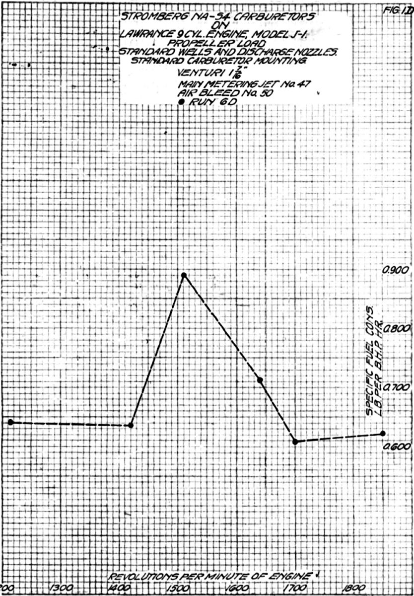
13 Sep 1922. Run 6D. A propeller load run was made to check the result of run 5D. The plugs remained clean throughout the run and the fuel flow and specific fuel consumption checked roughly with the data obtained on run 5D, that is, it was a reasonable quantity at full throttle and increased to a maximum, being very rich between 1,500 and 1,600 rpm and then back to approximately the full throttle quantity at 1,400 rpm, which was a very unreasonable fuel consumption curve (see Fig. 1D).
Run 7D. The carburetors were removed and the setting changed to 1.467" chokes, #44 main jets and #30 air bleeds. This setting proved somewhat leaner than the previous one and as the power output was low. The main jet sizes were increased to #43 and then to #40. The cylinder No. 5 exhaust valve clearance was found to be excessive, which was the cause of the loss of power and not the lean mixture. A propeller load run was then made with #40 main jets in the carburetors. The results of this run were more erratic and unreasonable than any previous run; the actual fuel flow at 1,500 rpm being greater than at 1,800 rpm full throttle. Careful observation was made of the engine vibration and in particular of the carburetors. The worst vibration period was at 1,500 rpm. At 1,600 and 1,700 rpm, the vibration was also considerable but not nearly as severe. The engine vibration on this setup seemed to take place about a horizontal axis through the crankshaft and perpendicular to the carburetor, and have a forward-backward motion.
The float chamber depression readings taken during all propeller load runs indicated a pressure above atmospheric at all speeds below 1,700 rpm. This was not the case on the Lawrance L-4 with the same NA-S4 carburetors, either on the test stand or in the airplane.
14 Sep 1922. Airplane P-185, powered by a Lawrance Model R-1 9-cylinder engine, was fitted with a manometer for reading float chamber depressions and operated on the ground. The following data were obtained:
| RPM | Float Chamber Depression, inH2O |
|---|---|
| 1,530 full throttle | 2.1 |
| 1,400 | 0.5 |
| 1,300 | 0.4 |
| 1,200 | 0.2 |
| 1,100 | 0.1 |
| 1,000 | 0.0 |
The vibration level was also noted carefully at all speeds. The most severe period was at 1,100 and 1,000 rpm, but was very little compared to the vibration of the Lawrance Model J-1 on the dynamometer test stand.
15 Sep 1922. In order to decrease the carburetor vibration at the engine's critical vibration speeds they were mounted on a common plate that was fastened to the dynamometer stand base plate by means of wooden supports and bolts. Rubber hose connections were fitted between this plate and the standard manifold flanges.
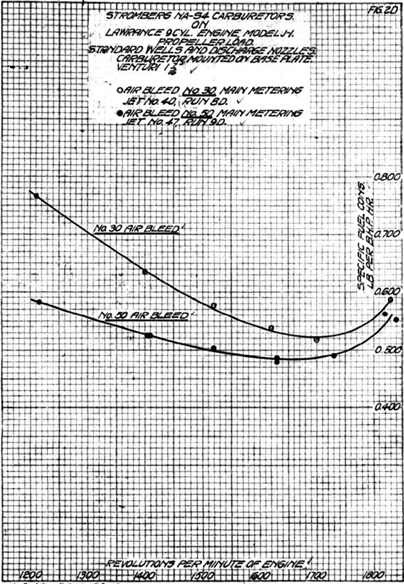
16 Sep 1922. Run 8D. A propeller load run was made with the same carburetor setting as used in run 7D (1.437" chokes, #40 main jets, #30 air bleeds, standard accelerating wells / discharge nozzles). This run indicated that most of the erratic carburetor function during previous runs was due to excessive vibration at certain engine speeds. As noted in Figure 2D the specific fuel consumption curve was smooth and it was possible to check the results very closely.
18 Sep 1922. Run 9D. The air bleed sizes were changed to #60 while the same 1.437" chokes and #40 main jets were used, A propeller load run was made from 1,800 to 1,000 rpm and an attempt made to check the readings at several speeds. As the dynamometer was being adjusted for the first check reading it was noticed that one magneto was firing. very irregularly. An investigation showed that the threads on the screws holding the distributor rotor to the distributor gear were worn. Both magnetos were than replaced with Dixie Model 900 magnetos. The readings at 1,800, 1,600 and 1,400 rpm were checked, and the specific fuel consumption curve obtained plotted in Figure 2D. It was noted that the smaller #50 air bleeda showed a lower fuel consumption at the lower speeds than the larger #30s and a little less "hook", with the point of minimum specific fuel consumption approximately 100 rpm less.
20 Sep 1922. Run 10D. The carburetors were removed and the following settings were installed: 1.437" chokes, #47 main jets, #40 air bleeds, and special #30 pulsation control nozzles and idle wells, furnished by the Stromberg Motor Devices Company. A sketch of the pulsation control nozzle and special idle well was shown in Figure 79. Two propeller load runs were made, one with the air bleed idle adjustment screwed up tight, which gave the richest idle possible, and the second with this adjustment screwed out as far as possible, or in the full lean position. Specific fuel consumption curves obtained during these two runs were shown in Figure 3D. It was noted that the idle adjustment had a very great effect on the specific fuel consumption at all speeds throughout the cruising range, not only in the curve shape, but also in the absolute values, the differences at full throttle being about 0.125 lb/hp/hr. This effect was expected as the fuel level depression at the idle adjusting needle behind the choke was much less than at the idle discharge nozzle so that when the idle adjustment was set lean or with this needle off its seat a large percentage of the air bleed thru the idle metering nozzle came from the idle adjustment, which was not affected by throttle position, rather than through the idle discharge nozzle.
 |
 |
| Fig. 3D | Fig. 4D |
Run 11D. The #30 pulsation control nozzles were replaced by #34 restrictiond. Two propeller load runs were made, one with the idle adjustments set full rich and one with the idle adjustments set 1/2 full lean, or unscrewed 20 notches from the full rich position. A run attempt was made with the idle adjustment set full lean, which was approximately 40 notches from the full rich position but the mixture was so lean that a slight full-throttle power drop appeared. Unscrewing the idle adjustment screw 20 notches from the full rich position, leaned the mixture considerably, but net enough to cause a power drop. Specific fuel consumption curves were plotted in Figure 3D.
In comparing these curves with those obtained in run 10D (with the larger pulsation control nozzles) it was noted that the "hook" was slightly less in both the full lean and full rich idle adjustment positions with a more pronounced difference in the curves evident with the idle set full rich. The absolute values were less, indicating a leaner mixture over the whole speed range with #34 nozzles than with #30 nozzles, The excessive idle adjustment effect was not affected to any extent by this decrease in pulsation control nozzle size.
21 Sep 1922. Run 12D. The special idle wells shown in Figure 79 were replaced by standard wells, the rest of the carburetor settings remaining unchanged, Two propeller load runs were then made, one with the idle set full rich and one with the idle adjustment screws turned out 20 notches from the full rich position. The results were plotted in Figure 3D. The curves indicated that the effect of the special idle well was negligible when the idle adjustment was set in the lean position and that the standard wells gave lower fuel consumption over the entire speed range with the idle adjustment set 1/2 lean, the decrease becoming greater as the spend decreased. In other words, the effect of the idle adjustment on the specific fuel consumption was less with standard wells than with the special wells. It was possible that this was caused by the increase in the amount of air flowing through the idle tube as compared with that flowing through the idle adjustment, the larger idle tube offering less resistance to air flow than the smaller or special idle tube.
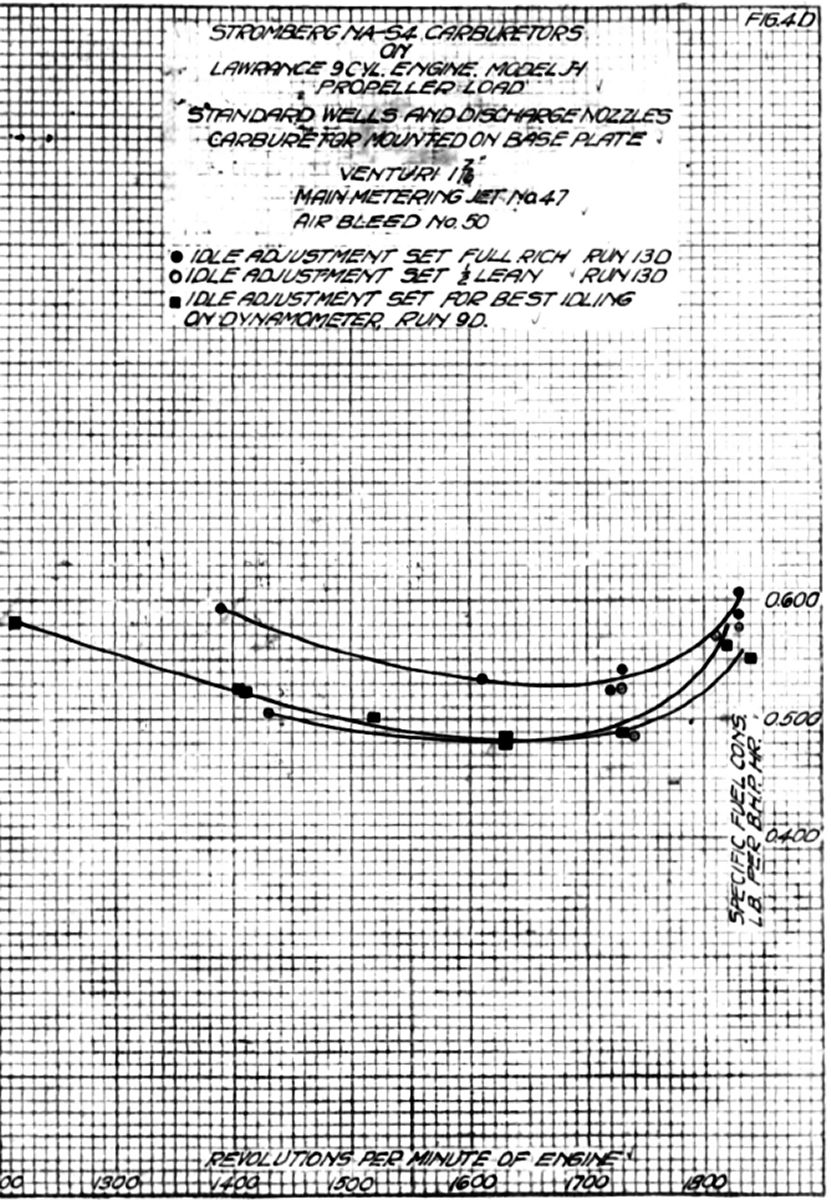
Run 13D. In order to determine the effect of the idle adjustment on the standard accelerating wells and discharge nozzles, the carburetor settings were changed as follows: 1.437" chokes, #37 main jets, #50 air bleeds, standard accelerating wells, discharge nozzles and idle tubes. Two propeller load runs were then made, one with the idle adjustment set full rich and one with it unscrewed 20 notches from full rich. The specific fuel consumption curves from these runs were shown in Figure 4D. The effect of the idle adjustment on propeller load specific fuel consumption was quite appreciable, particularly so at lower speeds. The maximum variation noted at full throttle was 0.050 lb/hp/hr. These results checked quite well with those obtained during run 9D. The idle adjustment position was not noted during run 9D, but from the data it would appear that it was comparatively lean, probably in a position that gave the best idle mixture for dynamometer operation. The idle adjustment setting of NA-S4 carburetors on Lawrence R-1 engines being used in flight was 15 to 20 notches out from the full rich position.
 |
 |
 |
| Fig. 5D | Fig. 6D | Fig. 7D |
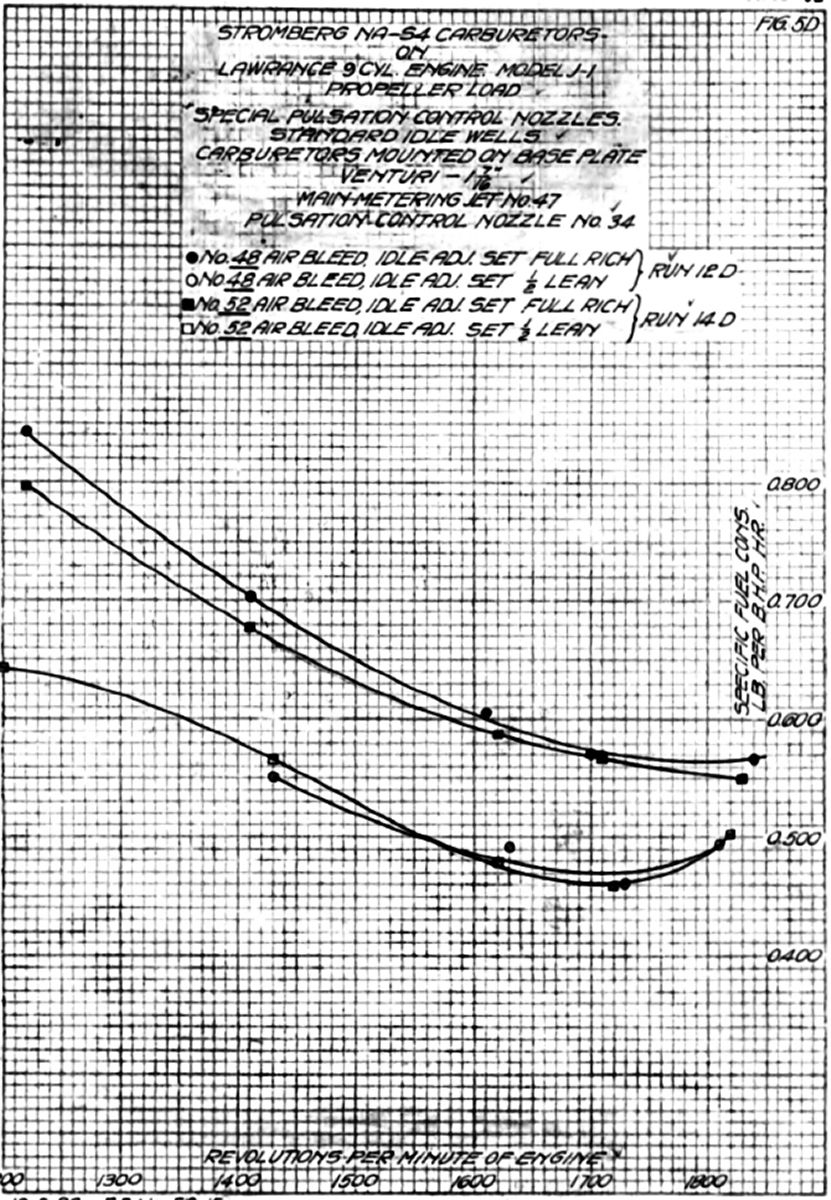
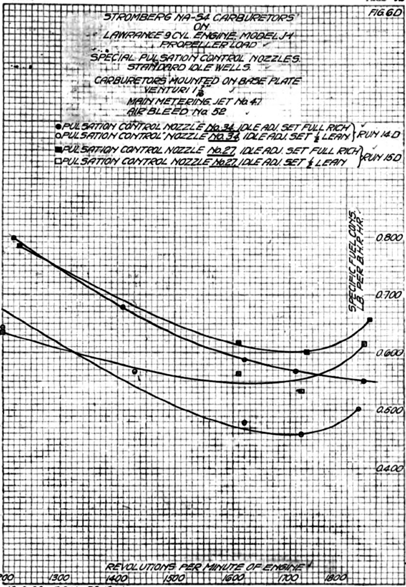
22 Sep 1922. Run 14D. The carburetor was set up with 1.437" chokes, #47 main jets, #52 air bleeds, #34 pulsation control nozzles and the standard idle tubes. An angle iron brace was placed across the engine mounting flange top and bolted to the engine stand vertical members. This was quite effective in partially overcoming the excessive engine vibration, particularly at 1,600 rpm. Two propeller load runs were made, one with the idle adjustment set full rich and one with the idle adjustment unscrewed 20 notches from the full rich position. The engine vibration was noted throughout these two runs; the angle iron brace reduced the vibration considerably, the lower cylinders seeming to vibrate more than the upper ones. The specific fuel consumption curves from these runs was plotted in Figure 5D. It was noted that the effect of the air bleed was negligible between full throttle and 1,600 rpm, becoming more apparent at lower speeds. The effect of the idle adjustment on the specific fuel consumption was practically the same with the #48 air bleeds as with the #52 air bleeds.
Run 15D. The #34 pulsation control nozzles were removed from the carburetors and replaced with #27 pulsation control nozzles. Propeller load runs were again made with the idle adjustment set full rich and full lean. Results of these runs were plotted in Figure 6D. It was noted that the larger pulsation control nozzle had three distinct effects upon the specific fuel consumption curve: fuel consumption was increased over the upper part of the speed range; the amount of curve "hook" was increased; the effect of the idle adjustment at higher speeds was decreased. The difference in specific fuel consumption at full throttle and the minimum at approximately 1,700 rpm was still less than that obtained with the standard setting.
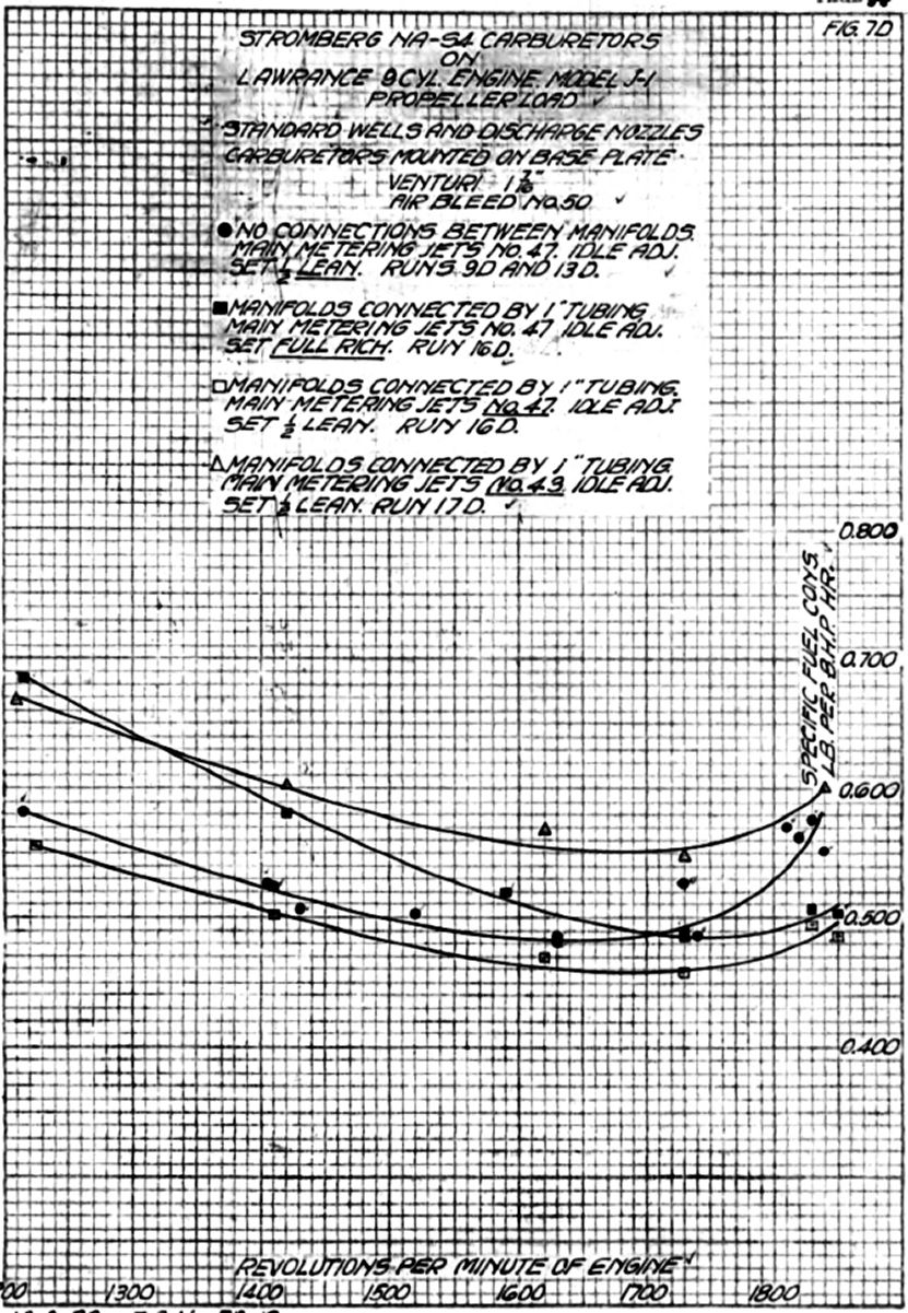
26 Sep 1922. Run 16D. The carburetors were set up with 1.437 chokes. #47 main jets, #50 air bleeds, and standard accelerating wells, discharge nozzles and idle tubes. As it was thought that the specific fuel consumption increase at full throttle and so-called "hook" in the sfc curves was due to the pulsations in the inlet manifold, the three manifolds were connected by short pieces of 1.0" tubing placed between the manifold and carburetor flanges. Propeller load runs were then made with the idle adjustment set full rich and also unscrewed 20 notches from the full rich position. Results of these runs were plotted in Figure 7D. This arrangement dampened the pulsations enough to decrease the specific fuel consumption curve hook quite an appreciably, the difference between full throttle and the minimum at approximately 1,700 rpm being approximately 0.035 lb/hp/hr as compared with 0.075 lb/hp/hr for the standard setting with no connections between the manifolds.
 |
 |
 |
| Fig. 8D | Fig. 9D | Fig. 10D |
Run 17D. In order to determine the effect of a richer mixture on the specific fuel consumption curve, the #47 jets were replaced with #43 jets. Data from the propeller load run made with this setting were shown in Figure 7D. The richer setting seemed to increase the "hook" a small amount but the curve was still much flatter over the entire range than that obtained with any other setting. The carburetor mounting used during the foregoing runs was, of course impossible for anything except dynamometer or torque stand testing but proved to give very consistent results, practically eliminating vibration effects on the carburetion.
28 Sep 1922. Run, 18D. The carburetors were mounted on the engine in the standard way and an angle iron placed across the engine supports with a brace to the engine mounting flange lower side. The manifolds were interconnected by means of 0.938" holes drilled through the manifold partitions. These holes were drilled directly behind the oil pump and the hole in the outside wall closed with a very thin shoulder-plug. This arrangement allowed about 0.016" clearance between the plug and the oil pump housing, which eliminated the necessity of any locking device. If this plug had came loose, oil or oil vapor in very small quantities would have been drawn into the manifolds. Before the propeller load runs, the carburetors were set up with 1.437" chokes, #43 main jets, #50 air bleeds, and standard accelerating wells and discharge nozzles. The results of these runs were plotted in Figure 8D. The jet size had very little effect on specific fuel consumption curve shape. The specific fuel consumption with this arrangement for balancing the manifold pulsations was considerably higher, and particularly so at lower steeds, than those obtained with the 1.0" tubing connections and the carburetors mounted separately on the dynamometer base plate.
Run 19D. In an effort to decrease the lower-speed fuel consumption, #47 main jets and #54 air bleeds were installed. The results of these runs plotted in Figure 8D indicate a slightly richer mixture from 1,600 to 1,800 rpm.
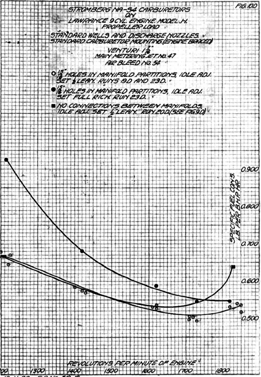
29 Sep 1922. Run 20D. From runs 18D and 19D it was apparent that the additional manifold lengths used when the carburetor were mounted on the dynamometer base plate had an appreciable effect upon the specific fuel consumption curve shape and absolute value. In order to definitely determine this effect a special plug was made that blanked off the hole in each manifold partition. This setup then corresponded to what has been termed the standard setting: 1.437" chokes and #47 main jets; #54 air bleeds replaced the #50s. A propeller load run was then made and checked, the results of which were plotted in Figure 9D. This run may be compared with runs 9D and 13D, the only setting difference being their air bleed size. The specific fuel consumption curve general forms were quite similar, the effect of the increased manifold length used with the remote carburetor mounting being to decrease the fuel consumption throughout the entire propeller load range.
30 Sep 1922. Run 21D. The #54 air bleed jets used in Run 20D were replaced with #50 jets and propeller load runs again conducted. The results of those runs were plotted in Fig. 9D. The air bleed effect was practically the some as that noted in runs 18D and 19D. See Figure 8D.
2 Oct 1922. Run 22D. Runs 17D through 21D were made with the idle adjustment set 20 notches out from the full rich position, which was referred to on curve sheets as "1/2 lean" and was very close to the normal idle adjustment used for flight. With the same carburetor setting as used in run 21D, three readings were made with the idle adjustment set 1/2 lean and a propeller load run made with the idle adjustment set full rich. Results of these runs were plotted in Figure 9D. The idle had very little effect upon full-throttle specific fuel consumption, the effect increasing gradually with engine speed decrease until at 1,200 rpm the specific fuel consumption difference was about 0.250 lb/hp/hr. Comparing these curves with those of Figure 4D, obtained with the same settings but different carburetor mounting, it was noted that the idle adjustment effect was more marked with the carburetors mounted on the engine than when mounted separately on the dynamometer base plate.
Run 23D. Reviewing all carburetor setting combinations tested, those of run 19D gave the flattest specific fuel consumption curve combined with the minimum idle adjustment effect with a service type of carburetor mounting. The carburetors were set up with a 1.437" chokes, #47 main jets and #54 air bleeds. The plugs in the 0.938" manifold partition holes were removed and final check runs made with the idle adjustment set 20 notches out from the full rich position (Fig. 10D). An effort was made to determine the effect of a backfire through one carburetor on the operation of the other two. The top cylinder (No. 1) usually ran the leanest. The mixture control lever on the middle carburetor that furnished the cylinder No. 1 mixture, was disconnected from the cross shaft so it could be operated independently. With all mixture controls in the full rich position, the load and speed were set at 1,700 rpm propeller load, which was the leanest setting on propeller load operation. The middle carburetor's mixture control was then set to full lean. This apparently had no effect on engine operation other than a slight decrease in speed. A #51 main jet was then substituted for the #47 jet in the middle carburetor and the procedure repeated. Even with this lean setting it was impossible to cause a backfire through the carburetor. This was probably due in part to the air temperature being rather high, approximately 80°F. A run of this kind was planned for when the air temperature was considerably lower.
| Run No. | Main Jet # | Air Bleed # | Special Carburetion Setting | Purpose and Remarks | Plotted Results Fig. No. |
|---|---|---|---|---|---|
| 1D | 45 | 50 | None | Check runs at full throttle to obtain nor mal engine operation. | --- |
| 2D | 45,47 | 50 | None | --- | |
| 3D | 47 | 50 | None | --- | |
| 4D | 47 | 50 | None | --- | |
| 5D | 47 | 50 | None | Std. propeller load run | --- |
| 6D | 47 | 50 | None | Check on run 5D. Erratic results | 1D |
| 7D | 44, 43, 40 | 30 | None | Propeller load run, #40 jet | --- |
| Carburetors Mounted on Base Plate to Eliminate Vibration | |||||
| 8D | 40 | 30 | None | Data obtained as comparison basis | 2D |
| 9D | 47 | 50 | None | Data obtained as comparison basis | 2D, 4D, 7D, 9D |
| 10D | 47 | 48 | #30 PCN, special idle well | FR, FL Idle. | 3D |
| 11D | 47 | 48 | #34 PCN, special idle well | FR, 1/2L Idle. Shows effect of smaller PCN | 3D |
| 12D | 47 | 48 | #34 PCN | FR, 1/2L Idle. Shows idle well effect | 3D, 6D |
| 13D | 47 | 50 | None | FR, 1/2L Idle. Shows idle adj. effect | 4D, 7D, 9D |
| 14D | 47 | 52 | #34 PCN | FR, 1/2L Idle. Shows smaller air bleed effect | 5D, 6D |
| 15D | 47 | 52 | #34 PCN | FR, 1/2L Idle. Shows larger PCN effect | 6D |
| 16D | 47 | 50 | Manifolds connected by 1" tubing. FR, 1/2 Lean Idle | Shows pulsation balancing effects | 7D |
| 17D* | 43 | 50 | Manifolds connected by 1" tubing. 1/2 Lean Idle | Shows rich setting effect | 7D |
| Carburetors Mounted on Engine | |||||
| 18D | 43,47 | 50 | 0.938" manifold partition holes | A possible pulsation-balancing service method | 8D |
| 19D | 47 | 54 | 0.0938" manifold partition holes | Shows effect of smaller air bleed | 8D, 10D |
| 20D | 47 | 54 | Manifold partition holes plugged | Shows effect of manifold partition holes | 9D |
| 21D | 47 | 50 | Manifold partition holes plugged | Shows effect of larger air bleed | 9D |
| 22D | 47 | 50 | Manifold partition holes plugged | FR and 1/2 Lean Idle | 9D |
| 23D | 47 | 54 | 15/16" manifold partition holes | FR and 1/2 Lean Idle. Final check on best carburetor setting and manifold combination. | 10D |
| *Runs 17Dthrough 21D were run with idle adjustment set 1/2 lean. | |||||
| FL = Full Lean; FR = Full Rich; 1/2L = 1/2 Lean; PCN = Pulsation Control Nozzle | |||||
5 Oct 1922. Airplane P-223 made a forced landing, wrecking the landing gear, wings and propeller. The Stromberg NA-S4 carburetor and air heater were not damaged. This ship had completed approximately nine hours flying since 6 Sep 1922, at which time the heater was installed. As this airplane was to be salvaged, the carburetor and air heater were removed and the expenditure order under which this teat was being conducted (E.O. 416-21), was temporarily closed out with the flying section.
11 Oct 1922. Airplane P-225, which was fitted with a Stromberg NA-S4 carburetor with a #37 pulsation control nozzle, was run up to determine the effect of the idle adjustment upon full throttle and cruising range operation. The maximum engine speed was 1,620 to 1,640 rpm. The idle adjustment showed no appreciable effect on the engine speed at full throttle, although the difference in the mixture strength could be detected by means of the mixture control, as a very slight opening causing an immediate drop in speed when the idle adjustment was set in the full lean position. The engine would idle with the idle adjustment set either full rich or full lean. The operational difference was changed very little, however, by changing the idle adjustment from full lean to within several notches of the full rich position.
19 Oct 1922. Airplane P-225 had completed approximately 17 hours flying since 25 August, at which time the pulsation control nozzle was installed. No complaints were received from the Flying Section concerning its operation. The following comments briefly summarized the results of the foregoing propeller load runs, made on the dynamometer stand with a Lawrance 9-eylindor Model J-1.
Vibration of the carburetors has a very marked effect upon the fuel flow and therefore the metering characteristics of the NA-S4 carburetor. During this test the carburetor vibration materially increased the specific fuel consumption.
The use of pulsation control nozzles decreased the amount of "hook" in the specific fuel consumption curve, increased the specific fuel consumption at the lower engine speeds and increased the effect of the idle adjustment upon the specific fuel consumption throughout the propeller load range. These effects were roughly inversely proportional to the size of the pulsation control nozzles. The use of the special idle tube in place of the standard idle tube increased the effect of the idle adjustment upon specific fuel consumption throughout the propeller load range. Enriching the mixture by means of the idle adjustment, with the pulsation control nozzle setting, had a tendency to increase the specific fuel consumption at the lower speeds of the propeller load range.
Small air bleeds were desirable in connection with the pulsation control nozzles, as this partially overcame the effect of this nozzle in increasing the specific fuel consumption at the lower speeds.
Inter-connecting the three manifold systems by means of 0.938" holes in the separating partitions was very effective in reducing the amount of "hook" in the specific fuel consumption curve. This arrangement did not appreciably increase the effect of the idle adjustment upon the propeller load operation, nor did it increase the specific fuel consumption at the lower propeller load speeds to the same extent as the pulsation control nozzle. The run made to determine the effect of a backfire in one manifold system upon the other two, was inconclusive.
12 Oct 1922. The following; memorandum was received on 11 Oct 1922 outlines the general policy as to the future development of the NA-S4 carburetor:
11 Oct. 1922
Mr. L.S. Hobbs:
Development of Stromberg NA-S4 Carburetor.C.C.
- I have discussed the question of future development of the Stromberg NA-S4 carburetor with Mr. Jones and Mr. Lawrance and the following conclusions have been reached.
- It was inadvisable to rely on interconnection of the manifolds on the model "J" engine to give a satisfactory metering curve for the following reasons:
This method will therefore have to be eliminated from consideration.
- This system cannot be used in the 3 cylinder engines.
- The fire risk was considerably increased.
- Mr. Lawrance states that the carburetion of the Navy Model J-1 engine was then quite satisfactory in regard to altitude control and operation throughout the engine range, but he still admits that the idle adjustment has a very great effect on the carburetor's mixture ratio up to full throttle. The Navy engines were using the new type pulsation control nozzles and an auxiliary passage between the float chamber and the mixture control passages.
- It would appear from the above considerations that the most promising way to obtain a satisfactory metering curve without the use of interconnected manifolds would be by means of the Stromberg pulsation control nozzle. Since this introduces the very serious defect of making the whole metering range subject to the idling adjustment, it was believed advisable to develop a fixed orifice type of idle adjustment similar to that on the U.S. 52 carburetor. It was believed that this would be a perfectly satisfactory method, provided the idling metering orifice size was determined for each engine type on which the carburetor was used.
- Mr. Lawrance claims that a recent Navy NA-S4 flight tests indicate that the carburetor with the auxiliary passage between the air passage and the float chamber possessed inherent altitude control. This was not believed probable since the results of flight tests were always unreliable, but it appears at least worth investigating.
- It was requested that you take up with the Stromberg Company the matter of e1iminating the effect of the idle adjustment on the metering range of this carburetor when using the pulsation control nozzle. It was also requested that you obtain complete information from Stromberg as to the exact size and position of the drilled hole between the control passage in the float chamber. Upon receipt of this latter information, a carburetor should be prepared with this change and tested in the carburetor test box for inherent control characteristics.
- To sum up the situation, we should continue our efforts to make the model NA-S4 carburetor satisfactory for the Lawrance Models J-1 and L-4 engines, without using such auxiliary devices as air heaters or manifold interconnections. We should also endeavor to find out immediately whether the arrangement flown by the Navy possessed inherent altitude control.
C.F. Taylor, Engineer in Charge, Power Plant Laboratory
Mr. Miller
Mr. Jones
18 Oct 1922. A letter was written to the Stromberg Motor Devices Company requesting definite information concerning the settings used in the Stromberg NA-S4 carburetors on the Lawrance 9-cylinder, Model J-1 engine that was used for Navy flight tests at Anacostia. These carburetors were supposed to possess inherent altitude control and were the ones referred to by Mr. Lawrance in his recent visit to the Engineering Division. (See paragraph 5 of the foregoing letter).The following memorandum covers several flight tests made by the Navy at Anacostia with a Lawrance 9-cylinder Model J-l engine:
Memorandum
30 Sep 1922.
Subject: J-1 Engine Flight Tests,"TS" Airplane
- On 25,26,27, and 28 Sep 1922, flight tests were conducted with "TS" airplane to determine altitude and general performance characteristics of Model J-1 engine. The original object of these tests was to determine whether the engine's altitude performance was satisfactory, it having been unofficially reported from several sources that there was an undue falling off in power at altitudes.
- Carburetor Altitude Characteristics. In the course of these flight tests, the carburetor control characteristics were thoroughly explored from sea level to 20,000 feet. The possibility of freak performance was eliminated due to the fact that these tests extended over four (4) days, and due to the fact that the performance noted was uniform on every occasion. Performance of the carburetor not installed on the production J-1 engines was normal in that with a given indicated air speed, the engine rpm at full throttle remained practically constant from 0 to 20,000 feet, there being only a very gradual and apparently uniform falling off in engine rpm amounting to not more than 30 rpm at 20,000 feet. The carburetor performance was remarkable in that the altitude control position for best performance remained constant throughout the entire range of altitudes from 0 to 20,000 feet; in other words, with the mixture control set for proper performance at sea level, no change in the altitude control lever position was required at any time from idling speed to full throttle and from 0 to 20,000 feet altitude
- No attempt was made to explain this carburetor characteristic. Suffice it to say this was an ideal characteristic and one that, so far as was known, did not occur in any other carburetor type yet built. There was nothing to indicate that the designer of the carburetor anticipated any such characteristics and it was believed that such characteristics has not heretofore been achieved without the provision of special automatic mechanisms,
- This matter should be very carefully studied and an attempt made to determine the underlying reasons for the peculiar altitude characteristics of this particular carburetor in an endeavor to duplicate these characteristics in carburetors used in other types of service engines.
- The engine idled poorly and there was some indication of poor metering characteristics at about 1,450 rpm. However, this was not believed to be a carburetor the fault, which will be mentioned later.
- In general, the carburetor performance on this engine was at least as satisfactory as that of other types in general service use.
- Engine Idling. This engine idled very poorly; in order to get smooth idling without danger of engine stoppage it was necessary to get the idling adjustment to a minimum of about 600 rpm on the ground. Attempts to adjust the engine to lower idling speed were unsuccessful. This was a most undesirable characteristic as the thrust delivered by the propeller at this speed to only slightly less than that actually necessary to overcome the rolling resistance of the airplane on the ground. The consequence was that, after landing, the airplane rolled along the ground (unless there was a strong head wind) for a distance of 400+ yards. In order to get into a reasonably small landing field, or to land on an airplane carrier deck, it was probably necessary to cut the engine switch unless this difficulty was overcome. This most undesirable condition had to be corrected if satisfactory engine service operation was to be realized. There was reason to doubt that the poor engine idling was attributable to the carburetor. It was suggested that the poor idling might be attributable to small air leaks in the intake manifold joints . This appears to be reasonable inasmuch as there were many joints between the carburetor and the cylinders. This matter should be immediately taken up with the manufacturer, which should suggest definite steps to provide better idling characteristics. The Engineering Division believed that this engine should be capable of idling at 300 rpm without loading up or stopping.
- Range of Operation. At certain times during the flight tests it was noted that when reducing the throttle from 1,700 rpm at full power to 1,500 rpm and below, and particularly in the 1,400 to 1,500 range, the engine missed intermittently and operated raggedly. Particular attention was paid to this during the last two days of the flight tests. The following conditions were noted. After starting the engine and while still on the ground, the engine operated smoothly at all speeds from idling to full power. After takeoff and climbing at full power to 5,000 feet the engine continued operating smoothly from idling to full power. The same conditions were noted at 10,000, 15,000 and 20,000 feet. However, after attaining altitude and gliding down, the rough operation at and below 1,500 rpm were noted, more at same times than others. It did not seem to coincide with any particular atmospheric conditions, nor was it continuous. Two possible causes were offered:
It was doubtful that spark plug fouling was the cause; after gliding in each case, the engine would pick up to its full power, and was left at full power for a sufficient time, it was believed, to completely clear the plugs, following which the same roughness was noted particularly in the range from 1,400 to 1,500 rpm. Additional flight tests were contemplated to determine the conditions under which this anomaly was expected to occur; it was possible that during the glide in cold temperature at and below freezing (on all tests altitudes reached were ay temperatures below 0°C) there may be a slight ice formation in the intake pipes, which may momentarily upset the carburetors metering characteristics at reduced throttle without seriously affecting it at full throttle. This was hardly likely, however, owing to the fact that in each case, after gilding, the engine at full throttle operated quite satisfactorily and up to its original power. It would be interesting in this respect to make parallel flight tests using air intakes heaters. The conditions noted above were not bad enough to cause serious concern, but the performance of the engine in this regard can be improved upon and attempts should be made to trace the cause of this action and to eliminate it if possible,
- Partial spark plug fouling due to idling during glide.
- Cooling during the glide.
- General Performance. In general, the engine operated smoothly and accelerated well. Oil temperature remained practically constant at 100° to 110°F. Performance might have been improved by use of a smaller oil radiator or lower viscosity oil. Oil pressure remained constant at about 25 psi.
- No fuel consumption measurements were made, inasmuch as no facilities were available. It was presumed, however, that the fuel consumption did not depart from that which was normally expected from ground test results.
- It may be concluded, therefore, that the J-1 engine's general performance was excellent. The metering characteristics of the particular carburetors that were used in this engine, the Stromberg NAU type, were excellent, and from indications obtained in these, the carburetor metering characteristics of this carburetor at varying altitudes were superior to any carburetor that has yet been developed. This may be accidental or peculiar to the particular carburetor used and should be verified through tests with other engines of the same type. The engine operation at throttled speeds was, in some conditions, not entirely satisfactory, although it was not worse in this regard than the some other engine types notably the Liberty 12, which was in general service use and considered to be reasonably satisfactory. The idling characteristics of thin particular engine were very poor. Wile th4 t his was inherent in the engine as a type, or whether it was due to a peculiar combination of circumstances which may be present in the particular engine used, remains to be determined. It may be said that this condition can be corrected by a little investigation and experimentation and tint the correction of this characteristic will not involve any change& in the general design of the engine.
- Finally, therefore, it may be said that the J-1 performance was, in general, satisfactory and that we may proceed to manufacturing airplanes using the J-1 engine with every assurance that no serious difficulty will be encountered with the engine as a type.
Note: The foregoing memorandum was received from Mr . F. Q. Mock of the Stromberg Motor Devices Company and was a copy or the memorandum written by Lt. Leighton of BuAer. The results of this flight series was discussed personally with Lt. Leighton during his recent McCook Field tour.
19 Oct 1922. The following letter was written to the Stromberg Motor Devices Co. briefly summarizing the results of the dynamometer runs on the Lawrance 9 cylinder, Model J-1, engine and enclosing the curve sheets from this run series.
19 Oct,1922
Stromberg HA-S4 Carburetors
Stromberg Motor Devices Company
56 -68 East 24th ST
Chicago, ILLAttention: Mr. F. C. Mock
- A dynamometer run series has just been completed by this Engineering Division on a Lawrance 9 cylinder engine, Model J-1, fitted with Stromberg NA-S4 carburetors. This test was conducted to investigate the motoring characteristics of this carburetor when fitted with the special pulsation control, nozzles furnished by you.
- The attached specific fuel consumption curves indicate the results obtained with various carburetor settings. These will be considered separately in order to dive briefly the conditions under which the data were obtained.
- Figure 1D shows the specific fuel consumption curve obtained with the standard setting with the carburetors subjected to rather severe vibration due to the use of a type of engine mounting that was not particularly rigid.
- Figure 2D shows the results obtained with the same carburetor setting and also with a larger air blood with the carburetors mounted separately on the dynamometer base plate and connected to the standard manifolds by short lengths of rubber hose. From these two curve sheets it was quite evident that serious carburetor vibration has a very appreciable effect upon the mixture strength.
- Figure 3D shows the results obtained with the special pulsation control nozzles both with the standard idle well and with the special idle well. Comparing the two curves obtained with the same size pulsation control nozzle and the same idle adjustment but with different idle wells, it appears that the standard idle well has an advantage over the special idle well in that it reduces the effect of the idle adjustment on the fuel consumption absolute values and also has a slight tendency to flatten the specific fuel consumption curve. Your opinion on the use of the special idle well with the pulsation control nozzle was desired.
- Figure 4D indicates the effect of the idle adjustment upon the standard carburetor setting and was much less than that with the pulsation control nozzle.
- Figure 5D shows the results of the runs made with special pulsation control nozzles and standard idle wells but with slightly different size air bleeds.
- Figure 6D shows the curves obtained with #34 and #27 pulsation control nozzles. With the carburetors still mounted on the base plate, the short manifold sections between the carburetors and the standard manifold flanges were connected by 1.0" tubing. Figure 7D shows the effect of these connections on the carburetor metering characteristics and also the effect of a large jet size on this arrangement. The specific fuel consumption curve obtained with connected manifolds and a #47 main jet was a closer approach to a straight line than any other setting tested.
- In order to determine the effect of this manifold interconnection , the engine was more rigidly braced to prevent vibration, 0.938" boles were drilled in the partitions between the manifolds, and the carburetors were mounted in the standard manner. Figure 8D shows the results obtained with the foregoing arrangement using two main metering jets and two air bleed sizes.
- The holes in the manifold partitions were plugged and several runs made with the standard carburetor mounting so that a comparison could be made between the carburetor metering characteristics of carburetors separately mounted on the dynamometer base plate and when mounted on the engine with a brace. Figure 9D shows the results of these runs.
- Figure 10D shows the results of final check runs made with holes in the manifold partitions open and closed and also the effect of the idle adjustment upon the fuel consumption with the manifolds interconnected.
- Although equalizing the pulsations at the carburetor by means of interconnecting the manifolds gave a very flat specific fuel consumption curve, it was thought that it would materially increase the fire hazard and the tendency for the engine to cut out completely in case of a backfire starting in one manifold system. This method of improving the metering characteristics was, of course, impossible for the 3-cylinder Lawrance engine. It was therefore desirable to use the pulsation control nozzle in these carburetors provided the effect of the idle adjustment on the fuel consumption throughout the cruising range could be reduced to at least as small an amount as that of the standard setting being used at the present time. The elimination of the idle adjustment would undoubtedly be the better method of obtaining a definite specific fuel consumption on propeller load that was unaffected by idle conditions. Three methods of accomplishing this suggest themselves: plugging the idle adjustment holes into. the idle well; drilling a definite size hole through the idle well wall or inserting an air metering plug in the idle well wall. The 1atter method appeared to be the easiest to accomplish and would probably give the best results as to smooth idling.
- Stromberg's ideas and cooperation on this matter were requested. It was hoped that Stromberg's Mr. Mock would visit the Division in the near future at which time this matter could be discussed in more detail.
For the Acting Chief of Divisions, E.T. Jones, Acting Chief, Power Plant Section
 |
| Fig. 113 |
23 Oct 1922. A letter received from the Stromberg Motor Devices Co. in reply to the Engineering Division's 16 Oct letter enclosing a blueprint (Fig. 113) showing in detail the carburetor setting and changes made for the Navy's flight test work at Anacostia, during which these carburetors apparently showed inherent altitude control. There was some doubt as to exact size of the pulsation control nozzle used for this flight as both #20 and #25 nozzles were given to the crew chief by Stromberg's Mr. F. C. Mock during his visit to Anacostia.
28 Oct 1922. A carburetor was fitted with the setting as show in Figure 113 with #25 pulsation control nozzles and placed in the carburetor test chamber to check the altimetric compensation characteristics.
31 Oct 1922. Run 1E. Altitude runs were made with the #25 pulsation control nozzle and the mixture control set full rich and then full lean, readings being taken at ground level, 5,000, 10,000, 15,000 and 20,000 feet altitude.
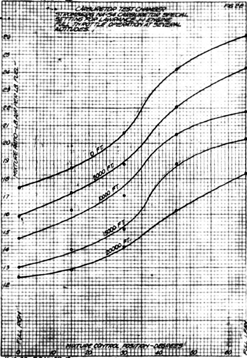
Run 2E. Mixture control runs were made at ground level, 1,000, 10,000, 15,000 and 20,000 feet altitude, with five setting of the mixture control at each altitude, Those two runs provided the data for the curves plotted in Figures 1E, 2E and 3E.
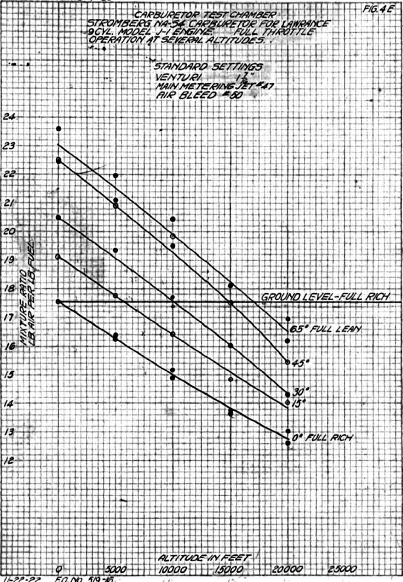
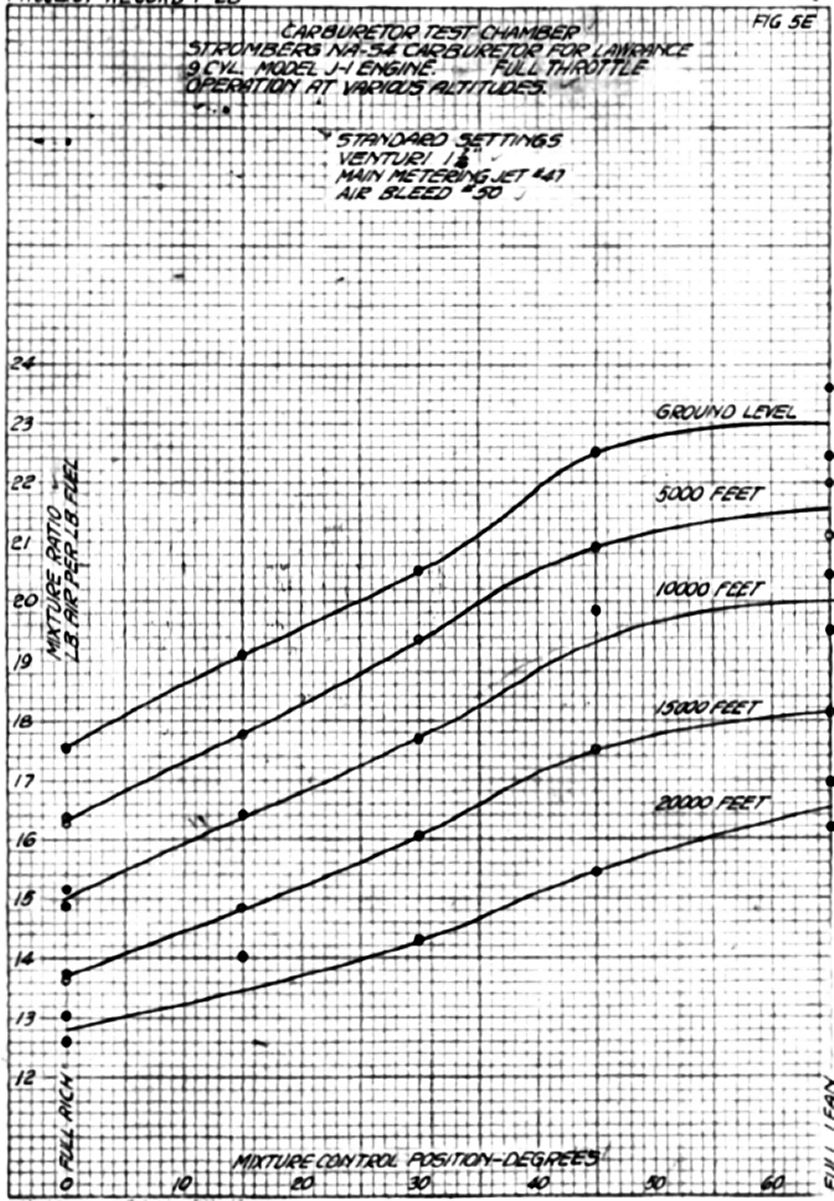
3 Nov 1922. The carburetor with the special settings was removed from the box and a carburetor with the following settings put in its place: 1.437" choke, #47 main jet, #50 air bleed, all other settings and parts were standard.
Run 3E. Altitude runs were made with the mixture control set full rich and full lean.
 |
 |
 |
 |
 |
 |
| Fig. 1E | Fig. 2E | Fig. 3E | Fig. 4E | Fig. 5E | Fig. 6E |
Run 4E. Mixture control runs were made at ground level, 5,000, 10,000, 15,000 and 20,000 foot altitude. Data from these two runs were plotted in Figures 4E, 5E and 6E. In comparing Figures 1E and 4E it was noted that the slope of the curves was practically the same but that the range of the mixture control was increased by means of the special setting. The standard setting indicated the maximum altitude at which ground level mixture could be obtained by means of the mixture control to be 17,000 feet, whereas the special setting increased this to approximately 24,500 feet. Figures 2E and 5E again indicate the greater range of mixture control obtained with the special setting and also indicate the effect of the float chamber venting method upon the mixture ratio for a given position of the mixture control valve. Figure 3E shows the variation of float chamber vacuum with mixture control position for various altitudes, indicating a very marked increase as the control was moved from 30° open to full open, or the full lean position. Figure 6E shows the same curves for the standard setting and indicates that the float chamber vacuum was approximately consistent for all mixture control positions at given altitude. The results of these runs with non-pulsating air flow, do not indicate in any way that this carburetor has inherent altitude control, although it was quite possible that pulsations might produce this effect to a certain degree.
3 Nov 1922. The engine from P-225 was brought into the shop for overhaul and the carburetor removed, overhauled and placed on the engine being conditioned for this airplane. The following setting was installed: 1.250" choke, #51 main jet, #30 air bleed, special idle well and #36 pulsation control nozzle.
6 Nov 1922. A carburetor with the following settings was placed on the engine in airplane P-249: 1.250" choke, #54 main jet, #50 air bleed, #34 pulsation control nozzle and a standard idle tube.
9 Nov 1922. The jet size in airplane P-249 was increased to #52. This was made necessary by the rough operation during cold weather.
22 Nov 1922. The main jet in airplane P-225 was changed from #51 to #50.
The following letter was received from the Stromberg Motor Devices Co.:
16 Nov 1922
Air Service, McCook Field, Dayton, Ohio.Gentlemen: Attention Power Plant Section
We have just received a copy of your letter of October 19th, the original apparently having been lost in the mail, and wish to thank you for the information contained therein. We note that the special pulsation control nozzle apparently has the same effect upon the mixture curve in actual operation of the motor that it has upon the mixture proportion under steady air flow in our suction machine. The somewhat undesirable characteristics of this type of nozzle, namely that it has a tendency to enrich the mixture at the lower end of the cruising range, also that it gives the idling adjustment an undue control of the power range, had already been indicated in our teats here, although the latter named effect was considerably stronger on the motor than in our suction test.
We think it probable, as your tests indicate, that these disadvantages can be nullified by the use of small size compensating bleeders and a modification in the idle adjustment.
The writer now expects to visit Dayton about the 20th or 21st of this month and will at that time show you some samples of an idling adjustment which will permit a limited adjustment of the mixture at extreme idle, and permit the selection of the desired mixture range from idling up to 800 rpm, but will not affect the mixture in the cruising and full power range. All our experience indicates that an adjustment of the idle alone was desirable, this being particularly the case on the Lawrance motor, as due to their construction, they have different degrees of manifold leak. The idling adjustment we propose to use would be such that it might be safety wired in place after being once set.
It seems to us that the information gained in this test regarding the effect of suction pulsations upon the mixture range, and the results obtained from connecting the different manifolds, was very important indeed. If you have not already transmitted this information to the Lawrance Company, we would like to have your permission to do so and also to the Naval Bureau of Aeronautics.
We note that with this new type of jet no difficulty to experienced in getting an enriched mixture between 1,550 and 1,700, whereas some trouble was experienced at this point on our previous test with the standard NA-S4 type of nozzle.
Fig. 122 Trusting that we may take up the further points of this subject on the writer's next visit, we are,
Yours very truly,
FCM.,FR Stromberg Motor Devices Company Engineering Department.
28 Nov 1922. Mr. F.C. Mock of the Stromberg Motor Devices Company arrived. bringing with him the special equipment noted in the foregoing letter, that is, a special adjustable idle discharge nozzle and a fixed idle air bleed (Fig 122). The new idle adjustment was installed on airplane P-249 and #52, #48, #30 and #35 air bleeds tested. The #30 air bleed gave the most satisfactory results. The idle adjustment had no appreciable effect on operation above 800 rpm. The approximate air temperature during these tests was 32°F.
 |
| Fig. 123 |
13 Dec 1922. A #49 main jet was installed in the carburetor of airplane P-225.
15 Dec 1922. An air heater as shown in Figure 74 was placed on airplane P-225 after it was reported that it was impossible to fly either airplane P-225 or P-249 during severe winter weather, the operation being very poor at temperatures of 25°F or below.
2 Jan 1923. As has been noted, the use of an air heater cut the full throttle speed appreciably, which was a very serious disadvantage as the maximum power possible from this engine was required for taking off with full fuel tanks and a heavy pilot. The tubes of the heater shown in Figure 74 were placed very close together thus restricting the air intake. A rearrangement and a decrease in the tube number in order to reduce this restriction was being constructed.
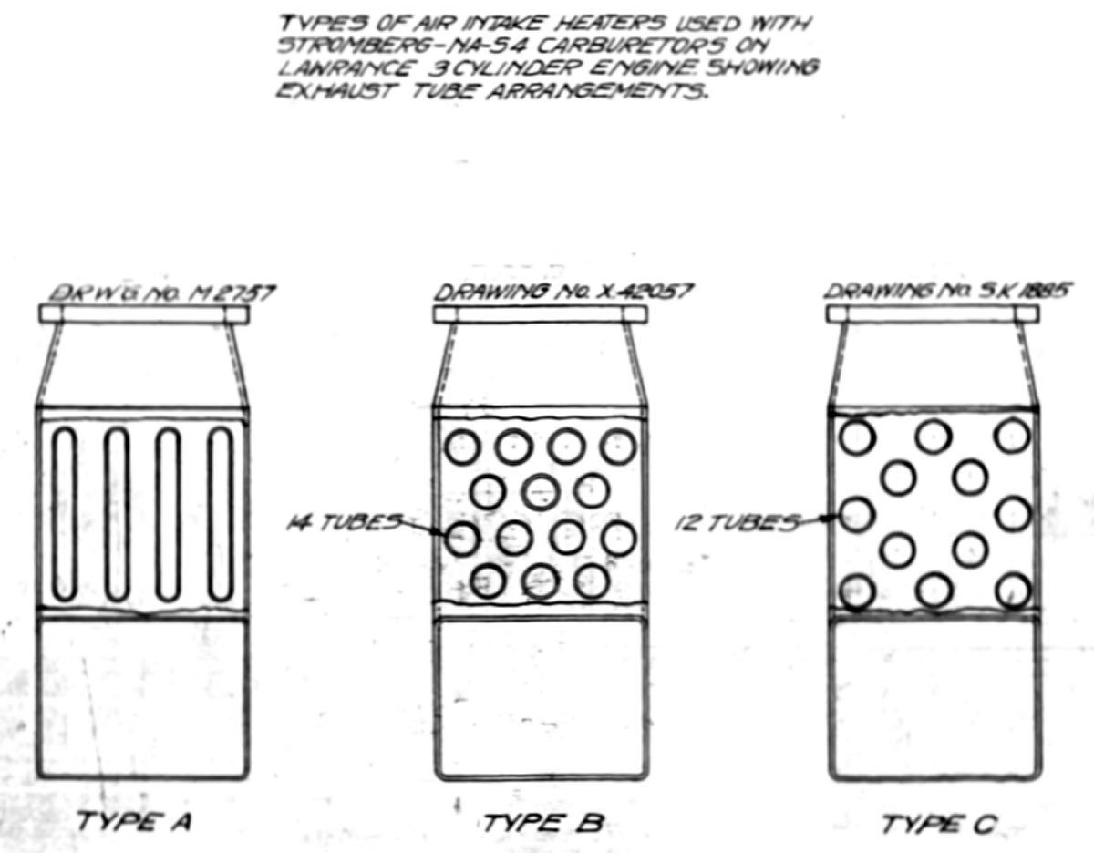
11 Jan 1923. A new air heater built according to drawing 8-42057 with 12 tubes spaced as shown in drawing SK-1885 (see Fig. 123) was completed and placed on airplane P-249. Airplanes P-225 and P-249 were run on the ground under various conditions.
The following carburetor settings were used:
| Airplane P-225 | Airplane P-249 | |
|---|---|---|
| Choke | 1.250" | 1.250" |
| Main Jet | #50 | #49 |
| Pulsation Control Nozzle | #36 | #34 |
| Air Bleed | #30 | #50 |
| Idle Air Bleed | Adjustable | #30 |
| Idle Tube | Special* | Standard |
| Idle Discharge Nozzle | Special* | Standard |
| *See Figure 113 | ||
The air pressure drop across the tubes at full throttle as measured by a manometer connected to the air heater just above the tubes and balanced against the atmosphere was 0.2 inches of water for the 12 tube heater on P-249 and 0.9 inches of water for the 14 tube heater on P-225.
The following observations concerning engine operation were made:
A comparison of the maximum speeds with the three air intake combinations tested seems to indicate that the addition of heat to the mixture increases the power output and that an appreciable decrease in power was caused by the restriction of the heater. This was not consistent with the results obtained with airplane P-225. This difference may be due in part to the fact that P-225 was very rich at full throttle, whereas P-249 was lean, and also showed a much smaller pressure loss due to the tubes than P-249. The number of variables between the two engines makes a direct comparison of the heaters based on maximum rpm inclusive. The air temperature during the foregoing runs was approximately 28°F.
9 Feb 1923. A carburetor with 1.625" choke, #49 main jet, #50 air bleed, #30 idle bleed, #34 pulsation control nozzle, standard idle tube and special idle adjustment was overhauled for installation on airplane P-225.
10 Feb 1923. The operation of the engine in P-225 with the new carburetor was noted at ground level with an air temperature of 21°F. The maximum rpm was 1,540 with the control set full rich. Operation between 600 and 1,000 rpm was very smooth. A slight rough spot could be detected at 1,100 and 1,200 rpm if the heater was not warm as after a prolonged idle. After running wide open and then throttling to these speeds the operation was smooth. The idle was good but would load up if idled for a few minutes. The acceleration was very good when the throttle was opened quickly after a abort period of idling when the manifolds had not loaded up. The engine would not stall, however, when accelerated with the manifolds loaded, but operation was very rough until the manifolds were cleared. If the idle adjustment was set too loan a flat spot appeared at the "transfer point" at 500 to 550 rpm where the engine would stop. This setting performed as well on the ground as any setting tried on the Lawrance 3-cylinder engine and it operation was to be checked in flight.
12 Feb 1923. Several air heater changes were approved by Mr. W.E. Donnelly, Assistant to Chief Engineer. Service tests with this carburetor and air heater have shown that the strengthened carburetor upper half and a brace between the bottom of the oil sump and the manifold flange were sufficiently strong so that the brace between the oil sump and air heater flange could be eliminated. In making this charge the projection at the front of the air heater flange became unnecessary. However, it was recommended that this brace be added anyway. Rearranging the tubes as shown by drawing SR-1885, Figure 123 was also recommended.
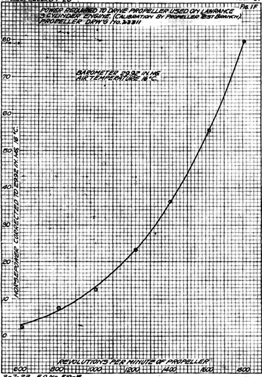
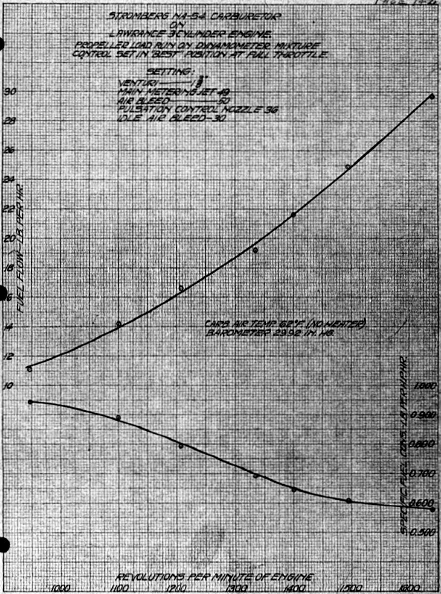
16 Feb 1923. In order to check the fuel consumption of the carburetor settings with pulsation control nozzles then used in flight a Lawrence L-3 with battery ignition was placed on the torque stand; no L-4 was available at the time. A standard propeller No. X-23311, A.S. No. 111046 was used as a load for the engine. This propeller type was being used on Lawrance L-4 engines installed in Messenger airplanes. A speed horsepower curve of this propeller was shown in Figure 1F. The volumetric fuel measuring tank was installed to take the place of the ordinary fuel scales for measuring fuel consumption. A –Stromberg NA-S4 carburetor with 1.375" choke, #49 main jet, #50 air bleed, #30 idle air bleed, #36 pulsation control nozzle, special adjustable idle discharge nozzle (Fig. 122) and standard idle tube. The 12 tube air heater that was being used by the Flying Section on Airplane P-249 was obtained for use during these runs.
Run 1F. Runs were made from full throttle to 800 rpm, with the heater installed and heated. Operation throughout this run was comparatively smooth. Considerable vibration was noted at 1,000 rpm but this seemed to be a critical speed rather than caused by any defect in carburetion or distribution. The heater pipe was then removed but the heater body left in place and a run attempted. The maximum speed was slightly greater with no heat than with heat, indicating that the drop in rpm previously noted was due to the heat supplied to the mixture rather than to any restriction or air flow change to the carburetor. At 1,300 rpm operation was so rough that readings were impossible. This irregular operation consisted of one or more cylinders misfiring, which occasionally caused a back fire through the manifold and carburetor, leading to all three cylinders cutting out momentarily. Average air temperature was 22°F.
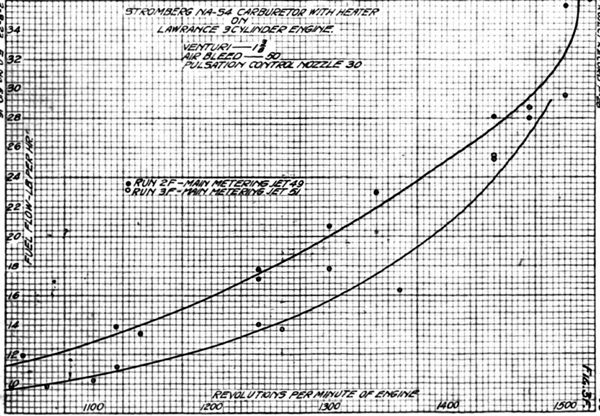
17 Feb 1923. Run 2F. The #36 pulsation control nozzle was removed and replaced with a #30. Runs were made from full throttle to 1,000 rpm The heater was used throughout these runs and the operation was smooth. This setting was considerably richer than that used on the previous day. Average air temperature was 18°F.
19 Feb 1923. Run 3F. In order to bring the fuel consumption down to approximately that obtained during run 1F, a #52 main jet was placed in the carburetor. This setting was too lean to run smoothly under throttled conditions so a #51 main jet was put in the carburetor. This jet size was satisfactory and two runs were made. Average air temperature was 26°F.
Run 4F. The #30 pulsation control nozzle was replaced by a #38, which was probably the smallest size that was safe to use. Runs were made with the heater from full throttle to 1,000 rpm and check runs made at full throttle with the standard air intake. The results of these runs were very erratic, giving points that were widely scattered on the speed/fuel consumption curve and therefore not forming a definite curve. In order to locate this trouble the fuel system was carefully checked, the valves inspected for leakage and several minor changes made, such as replacing valves not in use by pipe plugs or caps. Removal of the flowmeter made it possible to use a different control valve, which eliminated the fuel strainer from that part of the fuel system used in taking the fuel readings. The volumetric fuel tank was replaced by the more accurate volume gauge from the carburetor test chamber. Average air temperature was 32°F.
21 Feb 1923. Run 5F. Check runs were made with the same settings used in run 4F, the heater being used for all readings. These results were also rather erratic and seemed to indicate that some unstable condition existed in the carburetor fitted with the smaller pulsation control nozzle. This engine showed a very definite characteristic during this run that had also been observed during previous runs to a lesser degree, which was an appreciable speed loss after the engine warmed up. This amounted to 30 or more rpm and usually occurred within the first two or three minutes of full throttle operation. Average air temperature was 28°F.
Run 6F. The #36 pulsation control nozzle was again placed in the carburetor and a check run duplicating Run 1F conditions made. Average air temperature was 40°F.
Run 7F. The pulsation control nozzle setting was removed and the standard accelerating well and discharge nozzle substituted. A run was attempted at full throttle to 1,000 rpm Although the heater was used with this setting it was impossible to obtain readings at speeds below 1,300 rpm due to the irregular and very rough engine operation. The fuel flow readings showed very plainly that with this setting the full throttle consumption was greater and the consumption at approximately 1,300 rpm much less than that with the pulsation control nozzles tested with the same size main jet. Average air temperature was 40°F.
23 Feb 1923. Run 8F. The #36 pulsation control nozzle was again put in the carburetor and check runs made at full throttle with the heater and with the standard stack. Several consecutive readings were taken at full throttle under each condition and the engine allowed to warm up thoroughly. These runs show a marked decrease in rpm with the use of the heater as compared with the standard air intake. Average air temperature was 24°F.
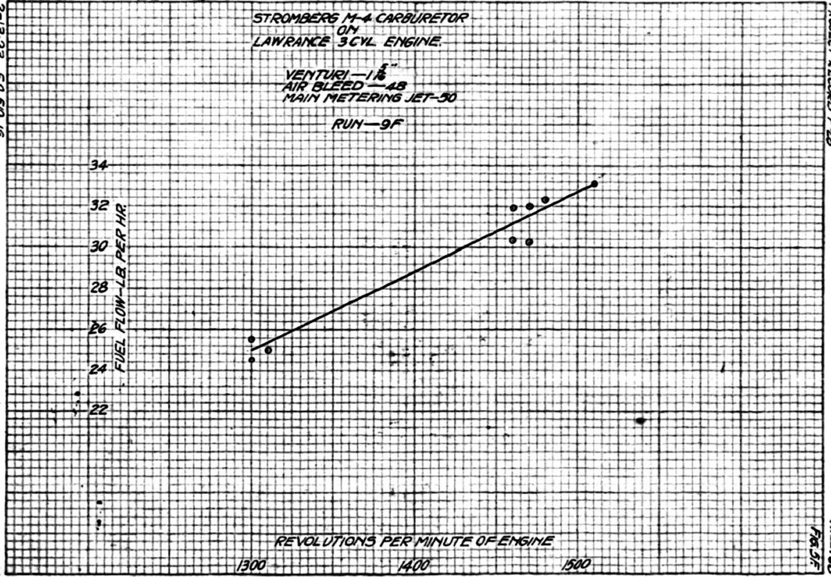
Run 9F. The Stromberg NA-S4carburetor was replaced by a Stromberg M-4 and runs attempted from full throttle to 1,000 rpm This carburetor was fitted with the standard setting that has been used in flight: 1.313" choke, #50 main jet, #48 air bleed. With this carburetor the engine was too rough for satisfactory readings at speeds below 1,300 rpm. This carburetor with its service setting gave a much richer mixture at all speeds than did the NA-S4 with settings that were satisfactory even in cold weather with the air heater. The distribution was so poor with the M-4 carburetor that the two bottom cylinders ran excessively rich at the throttled speeds and the top cylinder approximately normal as judged by the exhaust appearance. Average air temperature was 26°F.
24 Feb 1923. Run 10F. A second attempt was made to obtain fuel consumption readings from full throttle to 1,000 rpm with the M-4 carburetor but with the same results, the operation being very rough at the speeds below 1,300 rpm. Average air temperature was 25°F.
26 Feb 1923. Run 11F. The weather during the foregoing runs had been clear and cold, with air to temperatures ranging from 18°F to 32°F, with the exception of 21 Feb 1923 when the air temperature went up as high as 40°F. With the air temperature up to about 44°F. it was thought that the air heater could be dispensed with, therefore the standard air intake and #36 pulsation control nozzle was placed on the carburetor and a run started. Operation at 1,400 rpm was rather rough although not enough to affect the fuel consumption readings, but when a reading was attempted at 1,300 rpm the same distribution troubles as in all previous cases were again evident and readings were impossible. A #47 jet was used to replace the #49 and a second run attempted. At 1,300 rpm a very decided rpm decrease was observed before the completion of the fuel reading and the manifold exterior was covered with frost. The atmospheric conditions were very favorable to ice formation either outside or within the manifold, as it was raining slightly, the ground was thawing and considerable fog was evident. A steam line was run to the engine and placed with the open end very close to the manifold just above the carburetor. A very small amount of steam projected against the manifold in this way eliminated all troubles due to frost or ice formation on the throttle or in the manifold, allowing the completion of a successful run. Air temperature was 43°F.
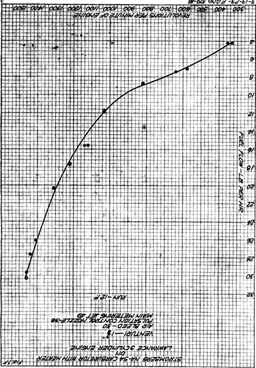
Run 12F. A #49 main jet was put back in the carburetor and a final check run made with the #36 pulsation control nozzle and air heater. Readings were taken from full throttle to idling speeds. Check runs at full throttle were also made with the adjustable idle discharge nozzle set "full rich" and "full lean". No appreciable difference in fuel flow was caused by the idle adjustment setting change. Average air temperature was 42°F.
 |
 |
 |
 |
 |
 |
 |
| Fig. 1F | Fig. 2F | Fig. 3F | Fig. 4F | Fig. 5F | Fig. 6F | Fig. 7F |
| Run No. | Main Jet # | PCN* # | Special Settings | Results | Results Fig No. |
|---|---|---|---|---|---|
| 1F | 49 | 36 | Heater with and without heat | For comparison with larger PCN | 2F |
| 2F | 49 | 30 | Heater with heat | Considerably richer than run 1F | 3F |
| 3F | 52, 51 | 30 | Heater with heat | Leaner setting to approximate 1F sfc | 3F |
| 4F | 49 | 38 | Heater with heat, std stack | Erratic results | |
| 5F | 49 | 38 | Heater with heat | Check of run 4F; still erratic | |
| 6F | 49 | 36 | Heater with heat | Check run of 1F | 2F |
| 7F | 49 | None | Standard discharge nozzle | Too lean to run smooth below 1,300 rpm | 4F |
| 8F | 49 | 36 | Heater with heat, std stack | Check run on 1F, 6F | |
| 9F | 50 | None | Stromberg M-4, 1.313" choke | Very rough below 1,300 rpm | 5F |
| 10F | 50 | None | M-4 | Rough operation below 1,300 rpm; no fuel readings | |
| 11F | 49, 47 | 36 | Std stack | Air temp 44°F. Icing until steam applied | 6F |
| 12F | 49 | 36 | Heater with heat | Final run. Full throttle to idle | 2F, 7F |
| * PCN = Pulsation Control Nozzle | |||||
Summary of Series F Torque Stand Runs
1 Mar 1923.The foregoing table indicates the torque stand runs made a Lawrance 3-cylinder engine fitted with the Stromberg NA-S4 carburetor and also the plotted data.
Figure 1F shows the power variation with rpm for the propeller used as an engine load during these runs.
Figure 2F shows the results of three runs made with a #36 pulsation control nozzle. These results were rather erratic compared with the results obtained on other engines with the same test equipment. This may be due to the greater effect of atmospheric conditions and carburetor combination, or to an unstable condition that may have existed in an air bleed jet and pulsation control nozzle when operating under pulsating air flow.
Figure 3F shows the data obtained with a #30 pulsation control nozzle and two jet sizes. The fuel flow curve with the #30 pulsation control nozzle and larger jet shows greater "hook" at high, speed and was somewhat 'flatter over the remainder of the propeller load range than that obtained with the #36 pulsation control nozzle. The form of the fuel flow curve with the #30 pulsation control nozzle and the leaner setting was practically the sane shape as that obtained with the No. 36 pulsation control nozzle.
Figure 4F show the fuel flow curve of the standard accelerating well and discharge nozzle over as great a range as it was possible to run with this setting, Although the air heater was used during this run, operation was so rough below 1,300 rpm that readings were impossible. This roughness was due to a lean mixture.
Figure 5F show the some type of curve obtained with the Stromberg M-4 carburetor. This carburetor, however, with the service setting gave a mixture that was too rich to fire the lower two cylinders regularly at speeds below 1,300 rpm. This carburetor was not provided with any means for heating the intake air.
Figure 6F shows the fuel flow curve obtained with a #36 pulsation control nozzle and slightly larger jet size put in to obtain smooth operation without the use of an air heater. This curve checks very closely with that shown in Figure 2F. The full throttle rpm, however, was considerably higher than that obtained with the heater. The effectiveness of a small quantity of heat added between the carburetor and the manifold tee was very forcefully demonstrated during the run made to obtain this data. A steam line, arranged so that steam projected against the manifold just below the tee, made it possible to put the mixture control in the full lean position and obtain smooth engine operation with a #49 jet in the carburetor. Without the use of steam the operation was very rough at the throttled speeds with the mixture control set full rich.
Figure 7F shows the fuel flow curve from the same data as that in Figure 2F, but over the full speed range, idling speed to full throttle. Comparison of Figures 2F, 4F, and 5F show that the fuel flow with pulsation control nozzle settings was between that obtained with the standard accelerating well and discharge nozzle on the lean side and the Stromberg M-4 carburetor on the rich side. The pulsation control nozzle setting gave the minimum fuel consumption that it was possible to operate the 3-cylinder Lawrence engine under various atmospheric conditions encountered in service, provided the heater was used when the air temperature was less than 40 or 50°F. A comparison of Figures 2F and 3F show that the difference in the fuel flow curve shape was very slight for the range of pulsation control nozzle sizes tested. This series of runs, most of which were made during cold weather, air temperatures between 20° and 30°F, indicates that the distribution on the Lawrence 3-cylinder engine was the limiting factor in obtaining low fuel consumption. The mixture distribution on this engine was vary sensitive to temperature changes. An air temperature of a few degrees changed the engine operation at cruising speed from very rough to comparatively smooth. This was more noticeable, of course, when the heater was not in use but could also be detected with the heater when throttling down from fall throttle when the heater was very hot or opening the throttle from idle when the heater was practically cold. It was recommended that the following setting be used for the Lawrance L-4 engines with the NA-S4 carburetor: 1.375" choke; #36 pulsation control nozzle; #49 main jet, #50 air bleed; #30 idle air bleed; standard idle well and special adjustable type of idle discharge nozzle.
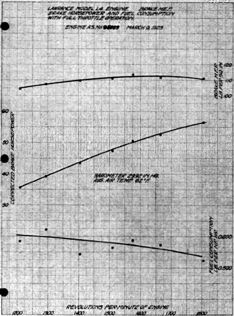 |
 |
| Fig. 141 | Fig. 142 |
9 Mar 1923. At the request of the Flying Section, a Lawrance L-4 engine with a Stromberg NA-S4 carburetor using the above settings was submitted for a calibration run. The results appear in Figures 141 and 142. The engine was to be installed in Airplane P-225 for tests to be conducted by the Flight Test Branch on different types of airplane wings.
Summary of Conclusions and Recommendations
Below are summarized the more important test results and the changes made during these tests.
Mechanical Failures and Changes. Both the 3-cylinder and the 9-cylinder Lawrence engines had critical speeds at which the vibration was very severe. This vibration caused numerous failures of the carburetor flanges during flight test work with the 3-cylinder engines Model L-4 in Messenger airplanes. The addition of an air heater to the carburetor increased the stress in the carburetor flange, making it almost impossible to operate the 3-cylinder engine for any length of time without carburetor flange failures. This matter was taken up with the Stromberg Motor Devices Company and the upper halves made with thicker carburetor barrel sections, larger fillets in all corners and the addition of strengthening vertical ribs. Ten spare upper halves were ordered for replacements and it was agreed that the strengthened upper halves would be used on all new carburetors manufactured by Stromberg.
Engine vibration, together with the increased weight of the carburetor and air heater also caused manifold failures just above the flange. This matter was taken up with the Lawrence Aero-Engine Corporation with the result that a flat plate acting as a fillet in the manifold tee was welded in place on all new three-cylinder manifolds.
In order to overcome these failures with the old type of carburetor flange and manifold, a brace was placed between the carburetor flange and the oil sump and also between the air heater flange and the oil sump when an air heater was used. At this Field the brace between the carburetor and the oil sump was a flat plate bolted at one end to the oil sump with the other end placed between the carburetor and manifold flanges. The Lawrance Aero-Engine Corporation incorporated a brace for the same purpose but of a slightly different design. Their brace, which was used on all new engines, was to be placed between the oil pipe flange on the oil sump and one corner of the carburetor flange, one point of fastening being used at each end. With the strengthened carburetor upper halves it was found unnecessary to use the brace between the air heater flange and the oil sump.
Three carburetor air intake heaters were tested. The original heater had four flat tubes, was considerably heavier than necessary and as the flat tube construction did not lend itself to production, a new heater using 0.5" steel tubes in place of the welded flat tubes was made up. The arrangement of these tubes was such that they offered considerable resistance to the air flow, making a tube rearrangement necessary. This last heater design (See Dwg. No. X-42057 with changes incorporated) was light enough to be used without mechanical failures, was effective in heating the air sufficiently to give smooth engine operation during cold weather and was recommended for service use.
Metering Characteristics. Fuel metering in this carburetor under various 1oad conditions was obtained by the standard Stromberg method of an air bleed jet. A "series" idle system was used; that is, all the fuel for the main and idle discharge nozzles passed through the main metering jet. Several types of main discharge nozzles were tested, the results indicating that the main discharge nozzle design had very little effect on the metering characteristics over the propeller load range. The standard type of accelerating well and discharge nozzle shown in Figures 57 and 58 gave a leaner mixture on propeller load at 100 to 200 rpm below full throttle speed than at full throttle, and under certain atmospheric conditions this mixture was too lean for smooth operation on propeller load. In order to overcome this and obtain flatter specific fuel consumption and fuel flow curves, the pulsation control nozzle was designed and tested (Figs. 79 and 80). In operation, the pulsation control nozzle, which took the place of the standard accelerating well, decreased the effect of pulsations producing a rich mixture at full throttle as compared with that at speeds immediately below full throttle. The theory of the operation of the pulsation control nozzle has already been described.
The idle adjustment on this carburetor, as originally designed, consisted of an air bleed to the idle well containing the idle tube. Due to the fact that at engine speeds at which the main discharge nozzle functioned, air was taken in through the air bleed and also through the idle discharge nozzle, and passed out through the main discharge nozzle. Thus, the setting of the idle adjustment had an effect on the fuel flow at full throttle and over the propeller load range. With the pulsation control nozzle, this effect was very appreciable and extended over the entire propeller load range with the tendency to cause a greater increase in fuel consumption at the lower speeds when set full rich than at intermediate speeds. To overcome this difficulty, the new type of idle adjustment (Fig. 122) was designed and tested. This consisted of a fixed idle air bleed and an adjustable idle discharge nozzle. The idle discharge nozzle adjustment affected the mixture strength from idle to approximately 750 rpm. The volume of fuel provided in the idle well to facilitate starting could be readily drawn up into the manifold by turning the propeller with the throttle closed and was effective in producing an easy start.
The metering system of this carburetor had sufficient variables, including pulsation control nozzle, main air bleed, idle air bleed, idle adjustment. and main metering jet sized so that practically any type of specific fuel consumption or fuel flow curve could be obtained on propeller load operation. The only changes in these variables that should ever be made in service were the idle adjustment and the main metering jet size.
The condition that existed throughout practically all of the tests, especially with the 3-cylinder engine and which seemed to be an inherent characteristic of this carburetor and engine combination was that of erratic fuel flow readings. The runs with the 9-cylinder Lawrance engine with the same carburetors showed definitely that the carburetors were materially effected by severe vibration. It was possible, that under certain circumstances an unstable condition existed in the metering system that would change the fuel flow. It may have also be caused by peculiarities of the manifold system. The manifolds on both the 3- and 9-cylinder engines showed very poor mixture distribution at all speeds with the possible exception of full throttle. The distribution at idle was so poor that it was almost impossible to obtain a carburetor setting that would fire all of cylinders evenly. This was most noticeable on the 3-cylinder engine where the operation became very ragged if one cylinder did not fire properly. A very rich setting was required for the top cylinder to get a rich enough mixture to fire. With this setting the lower two cylinders ran very rich and the lower part of the manifold loaded up with liquid fuel that made acceleration very poor after a prolonged idle as this liquid fuel had to be cleared before the engine would came up to speed. If the engine was not idled long enough for the manifolds to become loaded the acceleration with very rapid as well as slow throttle opening was excellent, there being no hesitation or missing as the engine accelerated to maximum speed. On propeller load operation, particularly during cold weather, this poor distribution showed up by causing a backfire in the carburetor due to a lean mixture in one cylinder. The backfire caused all cylinders to momentarily cut out. The carburetor and manifold combination on the 3-cylinder engine and also to a lesser degree on the 9-cylinder engine was very sensitive to changes in air temperature, poor distribution causing rough operation with lower temperatures, in some instances noticeable at 40°F.
Interconnecting the manifolds on the 9-cylinder engine reduced the effective pulsations on the carburetor, giving a very flat specific fuel consumption curve, and was much more effective in this respect then the pulsation control nozzle. The effect of the fuel head on the watering characteristics of the carburetor was very slight between 20" of gasoline and eight psi pressure, which was approximately 320" of gasoline.
The Mixture Control used in this carburetor design was of the air-port type, air being admitted between the main discharge nozzle and the throttle valve. The air-port passage had an area equal to 73.9% of the area of a 1.375" choke. Carburetor test chamber tests indicated this control to be effective in producing ground level mixtures to 20,000 feet altitude. Other carburetor test chamber results showed that the carburetor gave a normal mixture enrichment with increase in altitude both with the float chamber vented to the air intake and to the air-port passage.
Air Heaters: As noted briefly under the metering characteristics discussion, this carburetor/engine combination ran very rough at throttled speeds on propeller load with lean mixtures and also with fairly rich mixtures during cold weather and was very sensitive to air temperature changes. During the 1922 winter it was found impossible to operate the 3-cylinder Lawrance engines with Stromberg NA-S4 carburetors in Messenger airplanes without air heaters of some sort when the temperature dropped below 32°F. Air intake heaters were effective in producing smooth engine operation over the entire range of propeller load speeds, with the exception of extreme idle but reduced the full throttle rpm a slight amount. These heaters were not needed when the air temperature exceeded 50°F as the pulsation control nozzles produced a rich enough mixture to give smooth engine operation over the propeller load range.
6 Apr 1923. The following letter was received from the Lawrance Aero-Engine Corporation answering the Division's inquiry of 19 Mar 1923, concerning the carburetor settings furnished by the Lawrence Company on engines delivered to the Air Service.
April 3, 1923.
From: Lawrance Aero-Engine Corporation
To: Chief, Engineering Division, Chief of Power Plant Section, McCook Field, Dayton, Ohio.
Subject: Stromberg NA-S4 Carburetor SettingsIn reply to your letter of March 19th, in reference to the above subject, all the Lawrance engines supplied by us to the Air Service were equipped with Stromberg NA-S4 carburetors. Although some of the L-4 engines wore not originally equipped with them, they have since been converted and equipped with NA-S4 carburetors.
The L-4 engines were furnished with one NA-S4 carburetor having a 1.375" choke, #49 main jet, #61 idling jet and #52 air bleed. J-1 engines were furnished with three NA-S4 carburetors, the left hand one having a 1.437" choke, #46 main jet, #61 idling jet and #52 air bleed. The center and right hand ones had a 1.437" choke, #49 main jet, #61 idling jet and #52 air bleed.
The above covers the carburetor specifications for the J-1 engines furnished the Air Service on Air Service Order No. 408-22. On the first three J-1s furnished on Contract 558, all three carburetors were the same having a 1.437" choke, #49 main jet, #61 idling jet and #52 air bleed.
Lawrance Aero-Engine Corporation
HBR/B H.B. Ring.
25 Apr 1923. In order to determine the proper size of fixed idle air bleed plug for use it carburetors on the Lawrance J-1 engine, permission was secured from the Flight Test Branch to experiment with the idle setting in the carburetors on the Model J-1 engine in Airplane P-283. Adjustable idle discharge nozzles were borrowed from the Model L-4 engines in airplanes P-225 and P-249 and also from an engine awaiting overhaul in the dynamometer laboratory. This type of adjustment were installed in the carburetors on airplane P-283 and a #40 idle air bleed plugs tried. The mixture on extreme idle with this setting was very rich, an excessive amount of black smoke issuing from all exhaust ports and most of the cylinders fired only on every other compression stroke. Next, #35 and #30 idle air bleed plugs were tried, with the #30 air bleed giving a very smooth idle with practically no smoke in the exhaust. The adjustable idle discharge nozzles showed quite an appreciable effect upon the idling mixture when changed from the fall rich to the full lean position.
The type of fixed idle air bleed previously used on the Lawrance L-4 engine (Fig. 122) was unsatisfactory from an installation point of view. The chief difficulty in installing this typo of air bleed was the lack of proper clearance between the idle air bleed plug and the idle tube, which made it very difficult to start the air bleed plug straight into the carburetor body threads. When the air bleed plug diameter was reduced enough to provide proper clearance y, it was likely to be crushed at the end if screwed in tightly. A new type of air bleed plug was made up and tried in a carburetor (Fig. 148). This consisted of a smaller plug that was took the place of the old type idle adjusting needle, This was screwed in tightly and then soldered to the needle valve screw bushing, thus becoming in effect a part of it.
| Setting | Lawrence Model L-4 | Lawrance Model J-1 |
|---|---|---|
| (3-cylinder) | (9-cylinder) | |
| Venturi tube (choke) | 1.375" | 1.437" |
| Air bleed plug | #50 | #50 |
| Idle air bleed | #30 | #30 |
| Main metering jet | #49 | #47 |
| Idle well | Standard | Standard |
| Idle adjustment | New type* | New type* |
| Pulsation control nozzle | #36 | #30 |
| *see Figures 122 and 148 | ||
9 May 1923. The following information received from Mr. W. E. Donnelly, Assistant to the Chief Engineer, indicated the number and location of the Lawrance Model J-1 and Model L-4 engines that were purchased by the Air Service as of 17 Mar 1923.
| Type J-1 - 9-cylinder Lawrance engines - Engineering Division Contract No. 535 for three (3) engines: | |
|---|---|
| A.S. No. | Location of Engine |
| 68843 | Stock "E" |
| 68844 | At Lawrance Aero-Engine Corporation for remodeling as called for on P.O. 44665 |
| 68845 | At Dayton-Wright for TA-5 airplane - Contract 613 |
| Washington Order 408-22 for ten (10) engines, Air Service numbers 22-99 to 22-108, inclusive. | |
| A.S. No. | Location of Engine(s) |
| 22-99 | In P-280 - Huff-Daland TA-6 Airplane now in Assembly Bldg. |
| 22-100 | At Thomas-Morse Plant for Training Airplane on Contract 619. |
| 22-101 | At Dayton-Wright for 2nd PS-1 Airplane - Contract 408. |
| 22-102 | At Dayton-Wright for 3rd PS-1 Airplane - Contract 408. |
| 22-103 | Stock "E" |
| 22-104 to 22-108 | Not received - Will be shipped to Fairfield. |
Lawrence L-4 Engines
In the following report on the L-4 engines no attempt was made to show their location. In fact the information cannot be compiled as the record of deliveries was not available on the Washington Contracts.
| Quan | Type | CN or PO* | A.S. No. | Point of Delivery |
|---|---|---|---|---|
| 1 | L-2 | Eng. Div. PO 28279 | 94765 | McCook Field |
| 3 | L-2 | Eng. Div CN 228 | 94565,6,7 | Lawrence Sperry for Messengers |
| 1 | L-2 | Eng. Div PO 30603 | 94569 | McCook Field |
| 2 | L-3 | Eng. Div PO 32258 | 94595, 6 | Lawrence Sperry for Messengers |
| The above engines were all been remodeled into L-4s. | ||||
| 2 | L-4 | Eng.Div CN 387 | 95044,5 | McCook Field |
| 14 | L-4 | Eng. Div CN 388 | 95015 – 28 | 10 to Lawrance Sperry, 2 to Scott Field, 2 to Airship Mfg. Co. |
| 9 | L-4 | Eng. Div CN 403 | 95046 – 95054 | Lawrence Sperry |
| 9 | L-4 | Washington 113-22 | 22-1 – 22-9 | Scott Field |
| 25 | L-4 | Washington 342-22 | 22-54 – 22-78 | 20 to Lawrence Sperry for Messengers on CN 341-22, 1 to Mitchell Field, 1 to Langley Field, 1 to Boiling Field, 1 to Ellington Field, 1 to Kelly Field |
| 10 | L-4 | Washington 408-22 | 22-89 – 22-98 | Fairfield |
| 2 | L-4 | Washington 450-22 | 22-109, 110 | 1 to Langley Field, 1 to Ross Field |
| 78 | Total | |||
| *Contract Number or Purchase Order Number | ||||
In addition there were about nine (9) L-2 and L-3s that were purchased direct by the Goodyear Company and installed in Pony Blimps purchased by the Government; these were at the various lighter-than-air activities. However, Property Maintenance and Cost Compilation have been directed to obsolete these and replace them by L-4s.
The foregoing tabulation indicated that at the time there were 13 Lawrence Model J-1 engines fitted with a total of 39 Stromberg NA-S4 carburetors and 78 Lawrance Model L-4 engines fitted with 78 Stromberg NA-S4 carburetors in service or in the possession of the Air Service, representing a total of 117 NA-S4 carburetors. It was recommended that equipment be purchased to alter these carburetors to incorporate pulsation control nozzles and new type of idling adjustment. For this purpose, the following equipment was required, along with an allowance of thirteen sets for spares, six sets for carburetors to go on Model J-1 engines and seven carburetors to go on Model L-4 engines.
130 Idle air bleed plugs, Dwg No. X-44670.
130 Adjustable idle discharge nozzle assemblies, Dwg No. 44673.
130 Accelerating well discharge nozzle assemblies, Dwg No. X-44672.
85 Pulsation control nozzles, #36, Dwg No. X-44671.
45 Pulsation control nozzles,#30, Dwg No. X-44671
130 Pulsation control nozzle gaskets.
130 Accelerating well gaskets.
50 Main metering jets, #49.
50 Main metering jets, #47.
Instructions and drawings for the installation of this equipment by the various Air Service activities were prepared and forwarded with the equipment.
5 Jun 1923. Mr. F.C. Mock of the Stromberg Motor Devices Company visited the Engineering Division on 4 and 5 June . The matter of standardizing the Stromberg NA-S4 carburetor settings was discussed with him and he stated that no standard setting had been used in the carburetors delivered to the Air Service through the Lawrance Aero-Engine Corp. This was because that the carburetor operation on both three- and nine-cylinder engines Was not entirely satisfactory so that the setting was continually changed for experimental purposes both by the Engineering Division and the Lawrance Aero-Engine Corp. during a period when engines were being delivered to the Air Service. The service setting recommended as standard for the Air Service was, according to Mock, entirely satisfactory. He also told of his experiences with the idle on the Lawrance model J-1 engines.
According to Lawrance, the proper method for setting valve clearance was to set them at 0.010" cold. This clearance then became 0.055" when the engine became hot. The valve timing created a considerable valve opening overlap. The inlet valves opened 55° before the exhaust valves closed when the engine was cold and 19° when the engine was hot; the hot and cold timing was due to the valve clearance change. The manifold vacuum was greatly reduced at idle speeds by the valve overlap because air was drawn in past the exhaust valve on the suction stroke. This was undoubtedly an engine characteristic that made any carburetor adjustment for a smooth idle practically impossible. Mock recommended taking up the matter with the engine manufacturer for correction in future models.
Instructions for installing the new pulsation control nozzle and idle equipment for Stromberg NA-S4 carburetors and instructions for the installation, care and operation of these carburetors in service, together with the necessary drawings had been completed in preliminary form.
Instructions for the Installation of New Equipment on Stromberg NA-S4 Carburetors
Lawrance Model J-1 (9-cylinder) and L-4 (3-cylinder) engines fitted with Stromberg NA-S4 carburetors were somewhat rough at throttled spends with a propeller load, especially during cold weather. This roughness was primarily due to the lean mixture at certain speeds. In order to overcome this difficulty without excessive full-throttle a new type of accelerating well was designed and tested. The new accelerating well required new idle adjustment procedure, which was effective at speeds of 800 rpm or less and had no effect on the mixture strength at higher speeds.
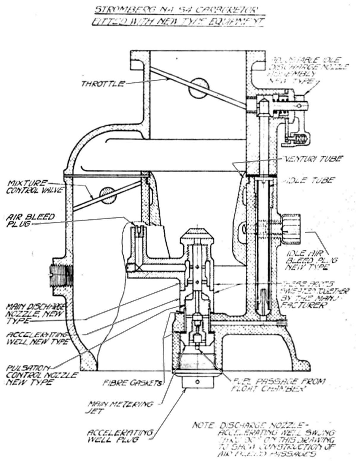 |
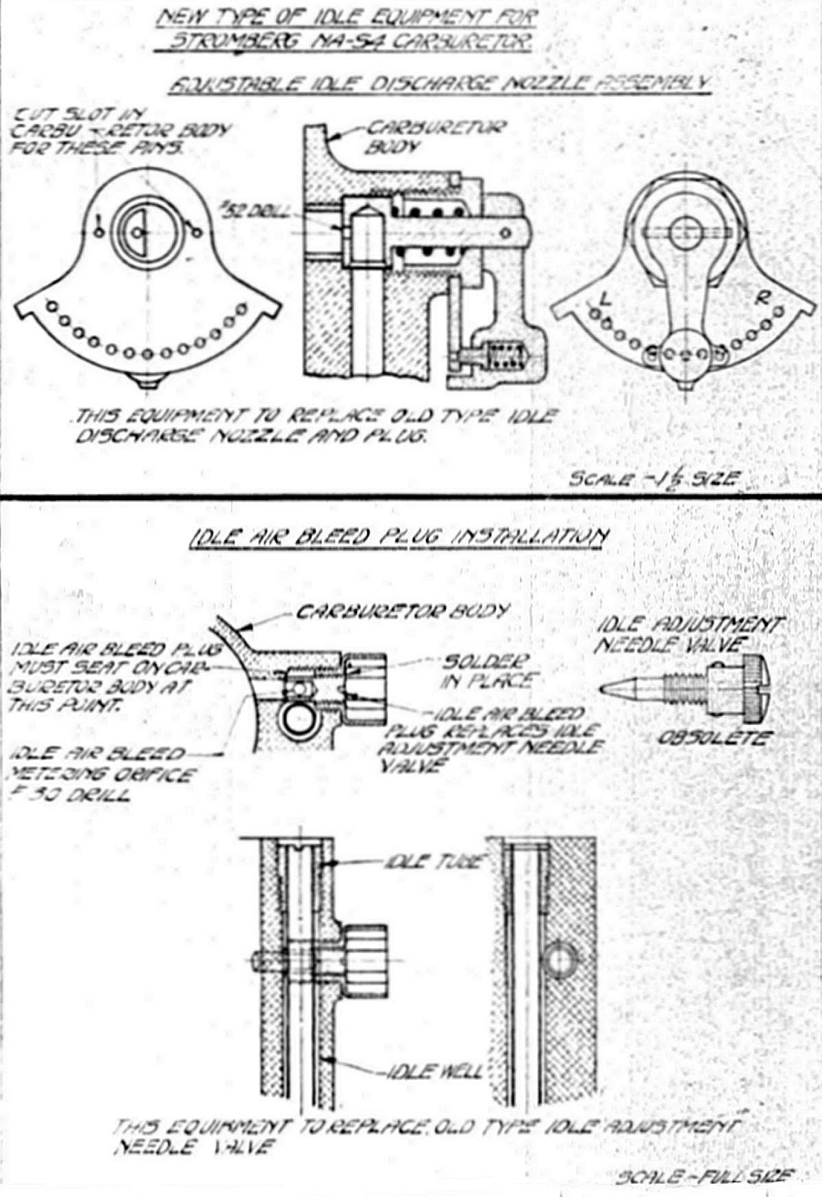 |
| Fig. 166 | Fig. 167 |
The new NA-S4 carburetor equipment appears in Figures 166 and 167, and consists of (1) an accelerating well – discharge nozzle assembly, (2) pulsation control nozzle, (3) adjustable idle discharge nozzle, (4) an idle air bleed plug and the necessary gaskets. The accelerating well – discharge nozzle assembly and pulsation control nozzle replaced the old type accelerating well and discharge nozzle. The adjustable idle discharge nozzle replaced the old type idle discharge nozzle and idle discharge nozzle plug. The idle air bleed plug replaced the idle adjustment needle valve.
Installation. Remove the carburetor(s) from the engine. Separate the carburetor body upper and lower halves. Remove the upside down jet, which passes through the venturi, the venturi, the plug under the main discharge nozzle, the main metering jet, the accelerating well and the discharge nozzle from the lower body half in the order named.
Assemble in the carburetor the pulsation control nozzle and accelerating well discharge nozzle assembly as shown in the Figure 166 drawing. Use a #36 pulsation control nozzle in carburetors for the Lawrance L-4 engine and a #30 in carburetors for the Lawrance J-1 engine. Be sure in assembling this equipment to use two gaskets, one under the pulsation control nozzle and one under the accelerating well discharge nozzle assembly. Place the main metering jet in the pulsation control nozzle using a #49 for the Lawrance L-4 and an #47 for the Lawrance J-1. Replace the plug under the main discharge nozzle, the venturi and the upside down jet.
Remove the idle discharge nozzle plug and idle discharge nozzle from the carburetor upper half. File or chip two notches in the idle discharge nozzle boss to take the idle discharge nozzle quadrant holding pins. Screw the idle discharge nozzle assembly into the carburetor with the adjustable arm pointing toward the air intake. Remove the idle adjustment needle valve from the carburetor lower half and screw the idle air bleed plug into its place, ascertaining that the plug end seats firmly against the carburetor body. Lock the idle air bleed plug in this position by soldering as shown in Figure 167. This idle air bleed plug assembly method produces a unit that will not be interchangeable with all carburetors without again soldering as the distance between the old type idle adjustment boss and that part of the carburetor body on which the idle air bleed plug seats varies in production. Assemble the upper and lower carburetor halves, safety wire all screws and plugs and the carburetor will be ready for installation on the engine.
Idle Adjustment. Before starting the engine, adjust the idle discharge nozzle to mid-position, half way between the rich (R) and lean (L) positions on the idle discharge nozzle quadrant. This idle adjustment was very easily adjusted to obtain smooth engine operation at idling speeds. The throttle stop and idle discharge nozzle adjustment should be so set that the engine idles smoothly at approximately 350 rpm. In order to insure smooth operation at speeds of 650 to 650 rpm the idle adjustment should be set as rich an it was possible without impairing smooth operation at extreme idle. If difficulty was encountered in getting the engine to operate smoothly at idle speeds the manifold system was to be checked for leakage. Air leaks could occur at any of the flanges or hose connections between the manifold and cylinders. On the Model J-1 each carburetor fed three cylinders so that rough operation or misfiring in a given cylinder was to be traced back to the carburetor feeding that cylinder. When facing the propeller as for engine starting, the cylinders were numbered consecutively in the direction of propeller rotation starting with No. 1 at the top. The center carburetor fed cylinders 1, 4 and 7, the right carburetor fed cylinders 2, 5 and 8, and left carburetor fed cylinders 3, 6 and 9. The valve timing and clearance on this engine was such that with a cold engine the inlet valve opened before the exhaust valve closed so that at idling speeds some air was drawn in through the exhaust valve during the first park of the suction stroke. If valve clearances were not uniform all cylinders, this amount of valve overlap would differ among the cylinders, producing a lean mixture in those cylinders with smaller clearances. The valve clearances therefore were to be correctly set correctly if idle adjustment difficulty was encountered.
With the release of these carburetor update, installation and adjustment instructions, Stromberg NA-S4 carburetor development was considered complete and the report closed.
Send mail to
![]() with questions or comments about this web site.
with questions or comments about this web site.
![]()
