Stromberg NA-S4 Development
Part 3: The Fixes
Compiled by Kimble D. McCutcheon
Published 16 Jun 2024
| As of early July 1922 the Stromberg NA-S4 carburetor, when installed on the Lawrance L-4 engine, was suffering from mechanical breakage and fuel/air metering issues. The attempts to fix these problems are described here. |
| Part 1: Description | Part 3. The Fixes |
| Part 2. Testing on the Lawrance L-4 | Part 4. Testing on the Lawrance J-1 |
Summary of Carburetion System Mechanical Failures , 30 Nov 1921 to 1 Jun 1922
Dynamometer: None
Torque Stand: Manifold broken across rear half above carburetor flange; no heater used
Airplane P-225, Carburetor Fitted with Heater
Manifold broken, at underside of tee.
Carburetor body cracked vertically through boss to which discharge nozzle was held by accelerating well.
Carburetor lower flange of broken around one stud hole.
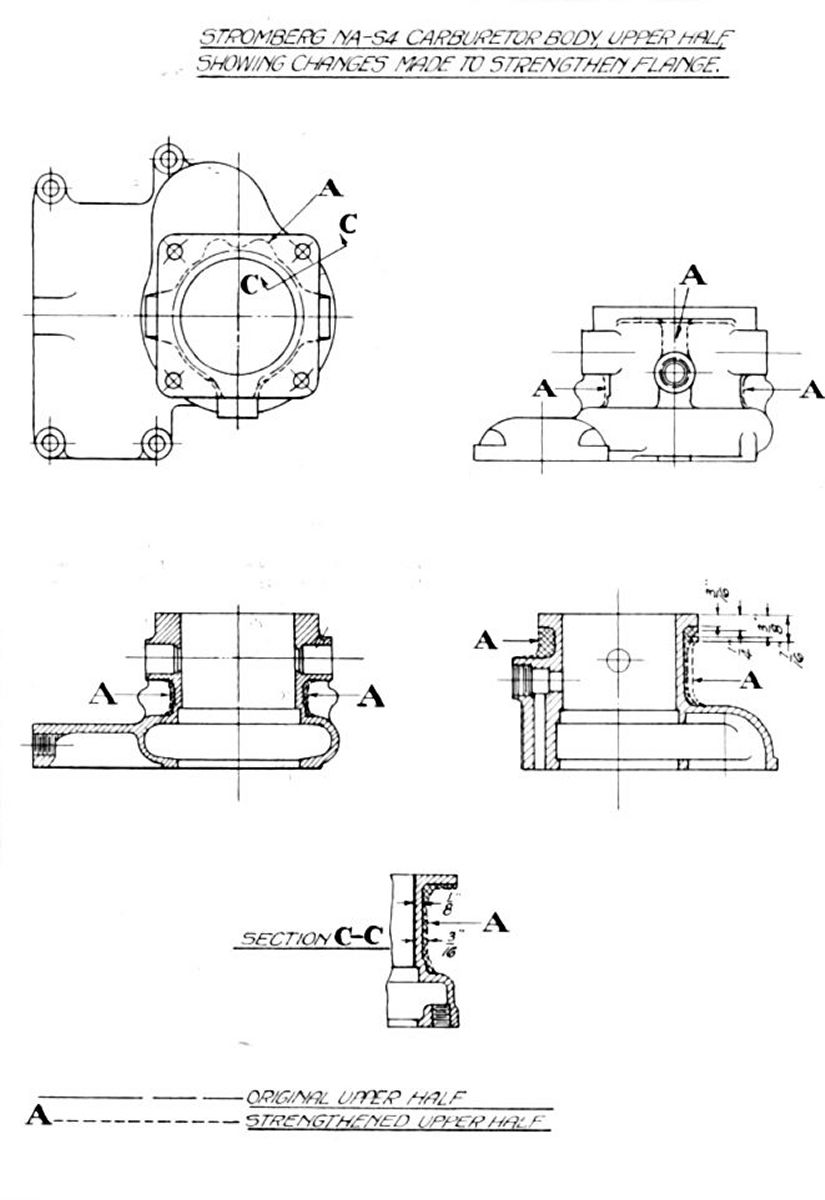
Five carburetors broken at upper flange around bolt holes.
Airplane P-223, Carburetor Fitted with Heater
One upper carburetor flange broken.
Note: very little flying was done with this ship.
Summary of Action Taken to Avoid Further Mechanical Failures
11 Jul 1922. The matter of carburetor and manifold mechanical failures was taken up with the Stromberg Motor Devices Company and the Lawrance Aero-Engine Corporation.
Ten carburetor upper halves, with the above changes. were ordered on 31 May 1922, under Purchase Order No. 41409, and received by the Division on 11 Jul 1922. These were to be used as replacements for carburetors broken was service. The weight increase caused by the upper-half changes was 0.17 lb, the old ones weighing 0.87 lb and the new 1.04 lb. As a precaution against breakage with the old type upper half, a brace was used between the air heater flange or the lower carburetor flange and the oil sump. A slip joint in the exhaust piping to the air heater was also used to prevent stresses at the carburetor flange due to the expansion and contraction of this pipe.
In a 14 Apr 1922 letter, the Lawrance Aero-Engine Corporation was notified of the Model L-4 engine manifold failures during flight and torque stand work. The Power Plant Laboratory asked for suggestions concerning a revised manifold design or a manifold brace of some kind. Several letters were exchanged, the results being that a vertical fin or brace was added to the manifold in a plane perpendicular to the crankshaft center line and a brace between the manifold flange and the oil sump designed. Lawrance was also notified that a brace was being used between the lower carburetor flange and the oil sump.
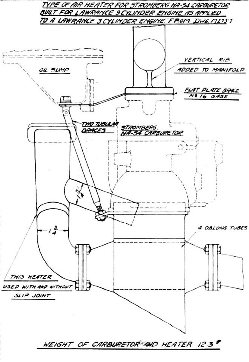
The air heaters used during flight tests on this carburetor were designed and built for experimental torque stand work on the Lawrance R-1 engine and were heavier than necessary. A memorandum report issued under Expenditure Order 516-14 covered the tests conducted with these heaters on the 9-cylider Lawrance engine.
|
|
|
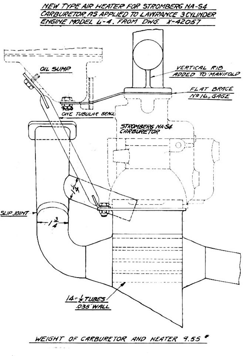
| Fig. 72 | Fig. 73 | Fig. 74 |
A new air heater design by Design Branch No.3 under the direction of Mr. Sheehan and with the cooperation of the Power Plant Laboratory, with a view to reducing the weight without impairing the heating qualities and also to produce a better production job. Drawing No. X-42059 was an installation drawing of this heater white No. X-42057 shows the air heater assembly and X-42127 the heater brace. Two of these heaters were made by the Division under Expenditure Order 416-21.
This design incorporated a tubular brace between an extension on the air heater flange and the oil sump (Dwg. No. 42127). Blue prints of drawings No. X-42059, No. X-42057, and No. X-42127 were sent to Lawrence along with a request that a boss be located on the oil sump, as shown on drawing No. X-42059, to accommodate the brace. Before receiving the above drawings, Lawrance had added a boss to the oil sump just below the sump flange and had castings made for the engines then on Washington order No. 408-22. This boss location made it impossible to use an elongated hole in the brace upper end as shown on drawing No. X-42127. This type of fastening, an elongated hole and cap screw, was used to decrease the possibility of setting up initial stresses In the carburetor flange by improper fitting of the brace.
As it was hoped to use the strengthened carburetor and manifold and the lighter air heater without any brace, Lawrance took no action to have new sumps made with the boss in the location shown on drawing X-42059. The above changes are shown in Figures 72, 73 an 74.
Summary of Metering Anomalies
Load compensation. Extensive dynamometer, torque stand, carburetor test chamber and flight tests conducted on the NA-S4 carburetor were necessary to investigate the unsatisfactory metering characteristics of the carburetor on the Lawrance L-4 under throttled conditions (propeller load). As noted in the detailed account of the tests, the first indication of any poor operation on propeller load was noted on the dynamometer during; the winter months when the air temperature was near 32°F. As fuel readings were being taken on propeller load at the loner speeds (1,000 to 1,200 rpm), the power dropped off and the engine backfired through the carburetor, hesitated and missed, indicating a lean mixture. This was attributed to ice formation in the manifold or carburetor. A steam jacketed air scoop eliminated the difficulty, as did higher air temperatures, say 60°F. The setting that gave good dynamometer operation was applied to a NA-S4 carburetor on a Lawrance L-4 engine in a Messenger airplane. Ground operation was rough at practically all speeds below full throttle, so larger jets were successively installed until smooth ground operation was obtained. This, however, was very rough below full throttle in flight. This roughness became apparent immediately upon closing the throttle slightly before sufficient time had elapsed for ice formation. The use of a carburetor air heater, utilizing exhaust heat from one cylinder corrected this fault in flight, making the carburetion comparable to that of the Stromberg M-4 carburetor.
Subsequent dynamometer and torque stand tests with carburetor settings that give smooth ground operation on the Messenger airplane showed a very definite hook or leaning out on propeller load with the lowest specific fuel specific fuel consumption at about 1,500 rpm. That this characteristic was the effect of pulsations or peculiarities of the manifold design was indicated by data obtained in the carburetor test chamber with smooth non-pulsating air flow. The curve of mixture ratio versus nominal rpm was practically a straight line (see Fig. 3C), the mixture becoming richer as the speed decreased. The mixture leaning was not apparent with the lean settings first used on the dynamometer. However, as the jet size was increased, the specific fuel consumption curved changed form, increasing at full throttle as expected but only very slightly at 1,500 rpm (see Fig. 16B). The larger the jet the more apparent this effect was.
Stromberg NA-S6, NA-S7 and NA-U6 accelerating wells, discharge nozzles, idle circuits, mixture controls, etc. have the same general construction as with the NA-S4 carburetor. The NA-S6 was tested in the Air Service W-1A engine and the NA-U6 on the Wright H-3. None of these show the unusual characteristics described above.
The use of an air heater on the NA-S4 so improved its operation that a comparatively lean setting (about 0.54 lb/hp/hr at full throttle) could be used for flight. The Stromberg M-4 fuel consumption was about 0.630 lb/hp/hr at full throttle.
Mixture Control. In the carburetor test chamber, the air port type of mixture control producing ground level mixture ratio to an altitude of approximately 10,000 feet. No flights had been made to determine the mixture control range. The air port screen had very little effect on the control range at any altitude. The mixture control's effect on propeller load mixture ratios also had not been observed in flight, but test chamber data indicated that the mixture control could produce a slight enrichment at lower speeds, which increased with the amount of control used.
Idling and Starting. Two idle adjustments were provided—idle discharge nozzle position and air bleed to the idle well were effective in providing a mixture ratio range but were not nearly equal in effectiveness as the air bleed adjustment produced very little mixture strength change. A smaller metering orifice in the idle discharge nozzle increased the air bleed idle adjustment sensitivity.
The extra large idle well provided for starting was very effective if the throttle was correctly handled. By turning the propeller over several times with the throttle completely closed and ignition off, a fuel charge was drawn into the cylinder. If the throttle was then opened slightly and ignition enabled an easy start could be made.
Stromberg was conducting tests on the NA-S4 in an effort to overcome the load compensation difficulties described above. It was hoped the improved carburetor would be satisfactory without the use of an air heater. Changes recommended by Stromberg were expected to be incorporated into several carburetors, and standard flight test made with and without the air heater. Dynamometer or torque stand runs were also planned to determine fuel consumption.
| Item | Weight, lb | |
|---|---|---|
| Old Type | New Type | |
| Heater box with extended flange for brace | 3.40 | |
| Exhaust pipe, lower | 0.95 | |
| Tail pipe | 1.10 | |
| Total of above items | 5.45 | 2.85 |
| Exhaust pipe, upper | 1.05 | 0.90 |
| Brace | 0.40 | |
| Carburetor | 5.80 | 5.80 |
| Total Assembly | 12.70 | 9.55 |
| Area, in² | ||
| Heating surface | 90.60 | 78.50 |
| Exhaust passages | 2.50 | 2.03 |
| Air passages* | 6.85 | 4.42 |
| Exhaust bypass | 2.07 | 1.11 |
| *The new heater used 0.5" tubes instead of the 0.563" tubes specified by drawing No. X-42057. The 0.5" tubes were in stock, while the 0.563" tubes were special. | ||
Send mail to
![]() with questions or comments about this web site.
with questions or comments about this web site.
![]()