Stromberg NA-S4 Development
Part 1: Description
Compiled by Kimble D. McCutcheon
Published 5 Jun 2024; Revised 14 Jun 2024

Stromberg NA-S4 Carburetor |
Carburetor development in the early 1920s rivaled engine development in difficulty. Although the aircraft carburetors then in use were simple in concept, the process of making them run correctly across an engine's power range was devilishly complex and extremely time consuming. The plodding cut-and-try methodology is almost painful to read at times. Yet Stromberg and the U.S. Army Air Service persevered and ultimately produced a viable carburetor for Lawrance engines.
This article was made possible through the generous material donation by John Riend. It is extracted from U.S. Army Air Service Report P-28, which documents testing accomplished under expenditure order number 519-65. The original is in the U.S. National Archives at College Park, Maryland, part of Record Group 342, RD Number 2655. |
Background
Charles Lanier Lawrance (30 Sep 1882 – 24 Jun 1950) was responsible for the first successful American air-cooled fixed radial aircraft engines. By 1919, Lawrance had built the Model L-2, a 3-cylinder radial with a 4.250" bore, 5.250" stroke, and 223.43 in³ displacement that produced 56.5 hp at 1,600 rpm and weighed 147 lb. Lawrance refined this engine and by 1923, the Model L-4 was producing 60 hp at 1,800 rpm from 175 lb.
Both the U.S. Army and Navy were interested in a larger engine, so Lawrance used nine of the L-4 cylinders to produce an engine displacing 670.30 in³ that produced 147 hp at 1,600 rpm and weighed 428 lb; This was known as the Lawrance Model R-1. The Navy wanted a still larger engine, which led Lawrance to design a new cylinder with a 4.500" bore, 5.500" stroke and 787.26 in³ displacement that produced 200 hp at 1,800 rpm and weighed 426 lb. This was the Model J-1. [Schlaifer, 163 – 166]
Lawrance initially used a Stromberg Model M-4 carburetor in the L-4. With the advent of the R-1 and later J-1, it was logical to use three carburetors, each of which fed three cylinders as with the L-4. This gave rise to the Stromberg NA-S4 carburetor. Rotary induction and superchargers were still in the future.
Description
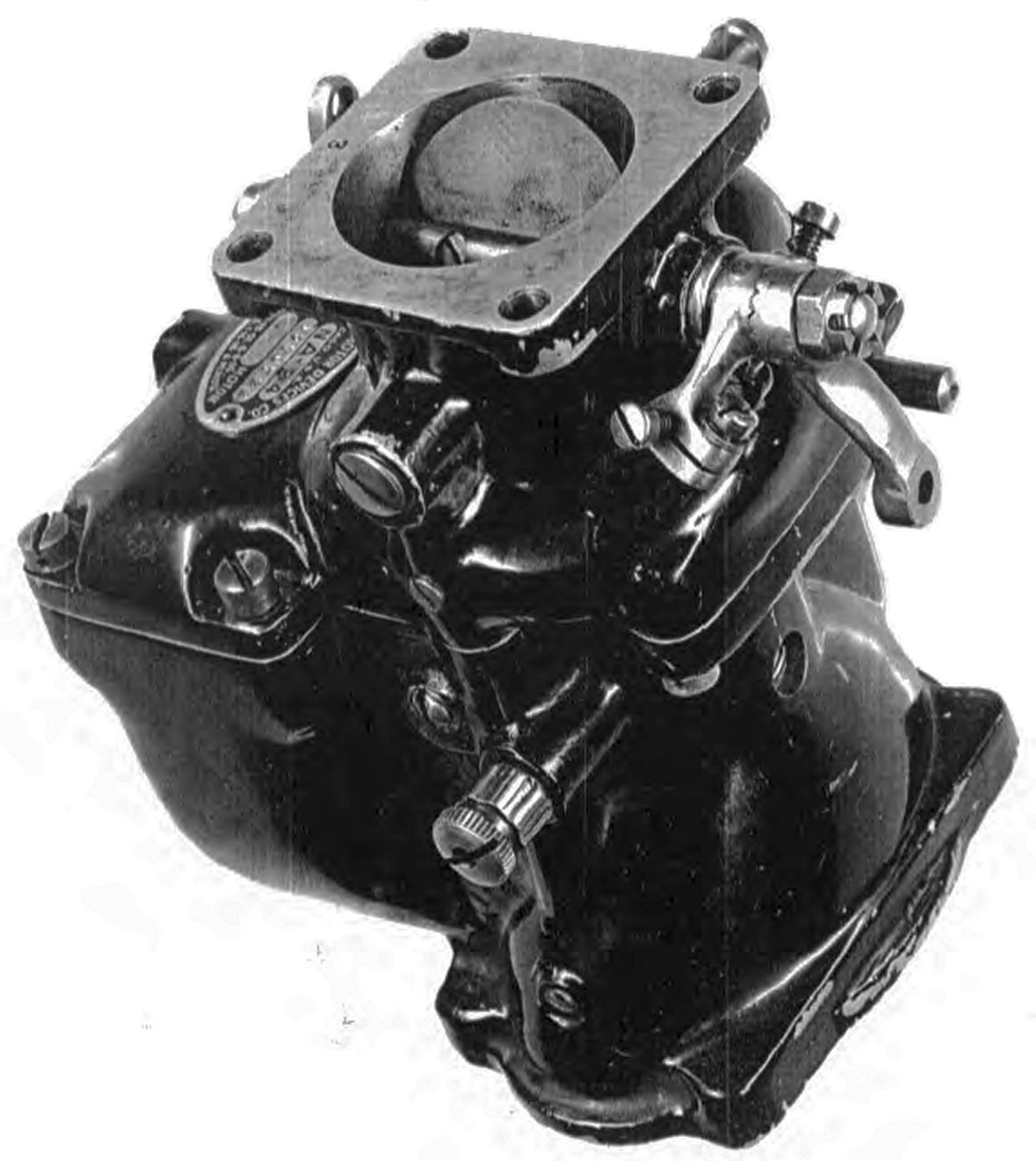
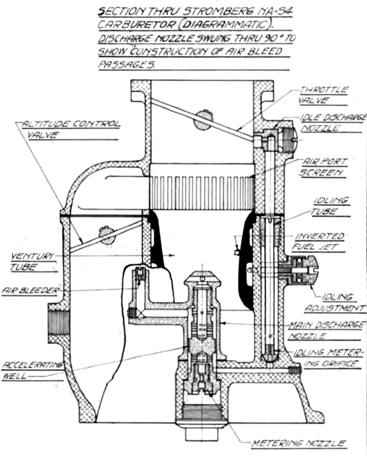
The Stromberg NA-S4 carburetor was designed and built by the Stromberg Motor Devices Company, Chicago, Illinois, for use on Lawrance three- and nine-cylinder engines. It was a single barrel, single venturi carburetor using the standard Stromberg method of load compensation, an air bleed jet. The removable air metering orifice was screwed into a vertical section projecting up behind the venturi and cast with the main discharge nozzle, The accelerating well passed through a projection of the carburetor body and was screwed into the discharge nozzle, thus holding it in place. The main metering orifice was screwed into the lower end of the accelerating well. Fuel passed through drilled passages in the carburetor body from the float chamber to the main metering orifice and into the central passage of the accelerating well. From this passage it passed through 12 holes in the well, through the narrow annular passage between the well and the discharge nozzle inside wall, through 24 holes in the well to the central passage, past the air bleed holes in the well and out the discharge nozzle.
Fuel for idling passed through the main metering orifice, out through the well and through the idling metering orifice at the lower end of the idle tube and through the idle discharge nozzle. Two idle adjustments were provided, one consisting of a needle valve that, when open, allowed air to enter the idling well into which the idling tube wais fitted, thus reducing the effective suction on the idle metering orifice. A coarser adjustment was obtained by rotating the idle discharge nozzle, thus changing its position relative to the edge of the butterfly throttle valve.
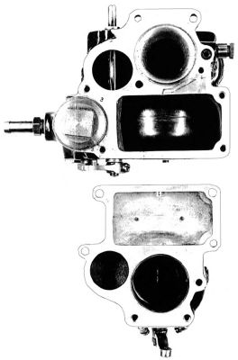
The mixture control was of the auxiliary air port type. By manually opening a butterfly valve, air flowed from the air scoop through an auxiliary air passage to the carburetor barrel between the throttle valve and the main discharge nozzle and venturi, thus decreasing the fuellevel at the discharge nozzle and leaning out the mixture,
An upside down or inverted fuel jet was provided to maintain engine operation when flying upside down. This was a jet screwed into the carburetor body, projecting into the venturi near the throat and connected by fuel passages to the float chamber. The engine was supposed to function normally in the inverted position until the fuel in the float chamber was exhausted.
Stromberg NA-S4 Carburetor
 |
 |
| Halves Parted Showing Auxiliary Air Port Mixture Control |
Longitudinal Cross Section |
Stromberg NA-S4 Leading Particulars
| Venturi (also choke) |
Single, sized in inches |
|
|
| Main Metering Orifice |
Stromberg, new type, drill size numbers |
|
|
| Main Discharge Nozzle |
|
|
|
| Discharge Openings |
Four #32 drill size |
|
|
| Air bleed passages |
#6 drill size. |
|
|
| Idling systems |
|
|
|
| Type |
Series with main jet, with adjustable air bleed to idle well |
|
|
| Idle tube mtering orifice |
#62 drill size. |
|
|
| Air bleed needle seat |
#16 drill size |
|
|
| Discharge nozzle metering orifice |
#52 drill size. |
|
|
| Mixture control |
|
|
|
| Type |
Auxiliary air port |
|
|
| Butterfly valve passage diameter |
1.375" |
|
|
| Butterfly valve passage area |
1.485 in² |
|
|
| Air port opening in percent of choke area |
| |
|
Percent choke area |
| Choke Size |
Choke Area |
with screen |
without screen |
| 1.125" |
0.994 in² |
110.2 |
149.4 |
| 1.250" |
1.227 in² |
89.3 |
121.0 |
| 1.375" |
1.485 in² |
73.9 |
100.0 |
| Upside down jet |
#45 drill size |
|
|
| Float needle seat |
#9 drill size |
|
|
| Weight without air scoop |
5.75 lb |
|
|
References
Schlaifer, Robert. Development of Aircraft Engines (Boston, MA: Harvard University, 1950).