U.S. Manned Rocket Propulsion Evolution
Part 8.31: The Saturn Instrument Unit (IU)
Compiled by Kimble D. McCutcheon
Published 15 Aug 2021; Revised 12 Nov 2025
|
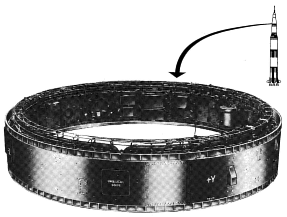
The Saturn Instrument Unit (IU), a squat cylindrical structure atop the Saturn IB and Saturn V S-IVB stage, contained the guidance, navigation, and control equipment responsible for managing all Saturn stage functions from the launch pad, into earth orbit and in the case of the Saturn V, on to a lunar trajectory. It also contained telemetry, communications, tracking, crew safety , electrical power and environmental control systems. Three IU Versions were built; Version 1 and 2 was used on Saturn I rockets, while the larger-diameter Version 3 (discussed here) was used on Saturn IBs and Saturn Vs. The Version 3 IU was 260" in diameter, 36" tall and weighed about 4,400 lb. Twenty two IUs flew. | |
| Saturn IB and V IU | ||
IU Structure
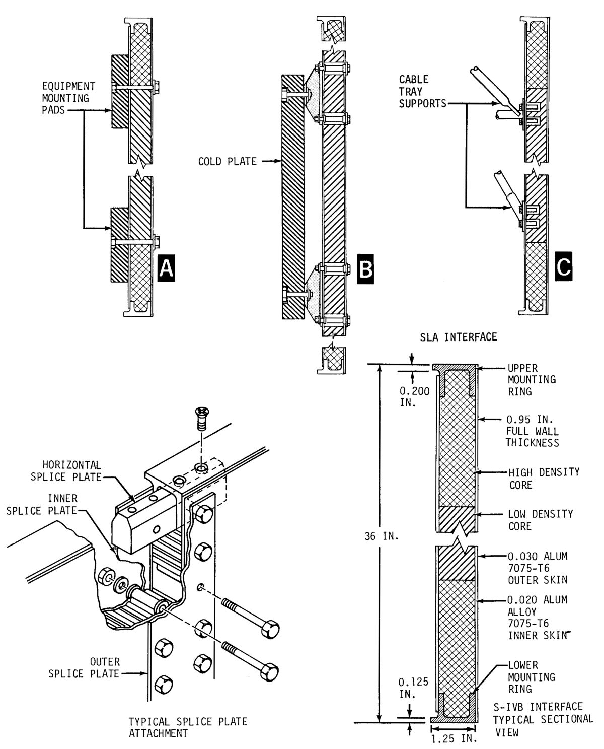 |
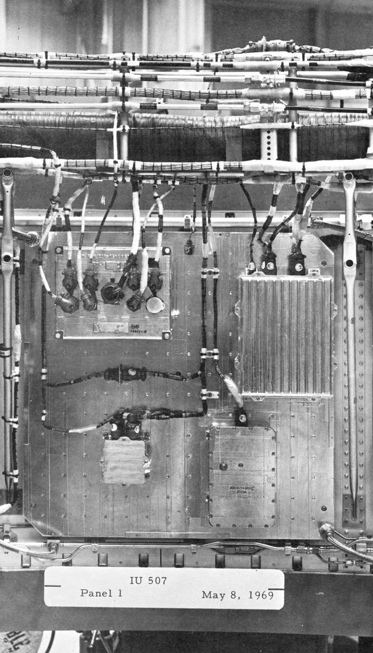
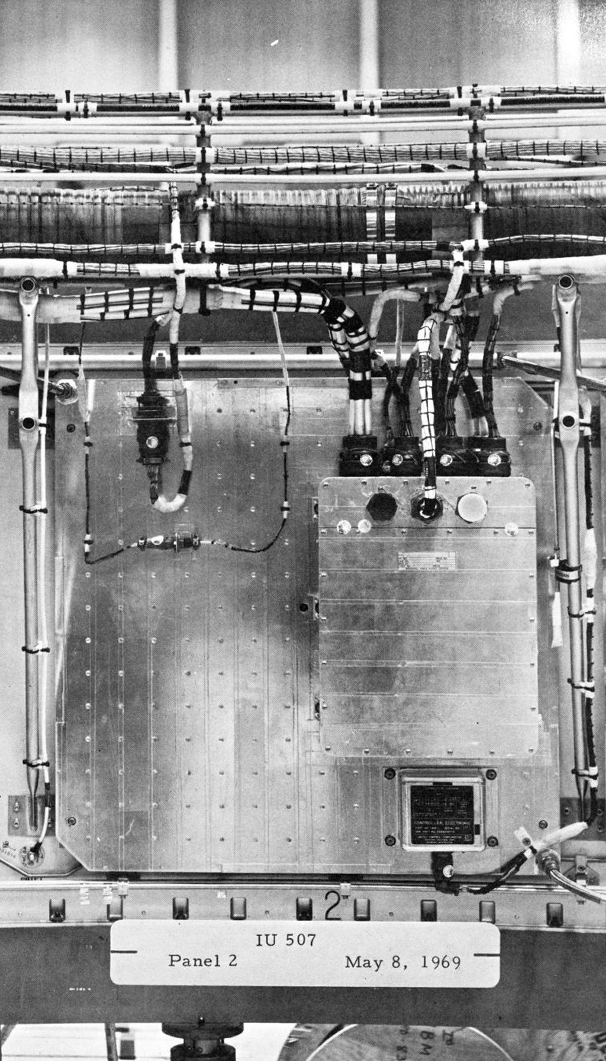
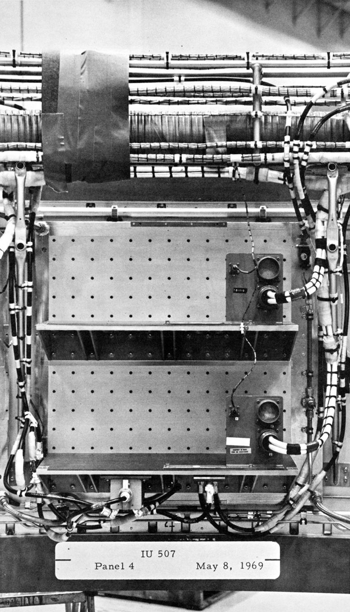
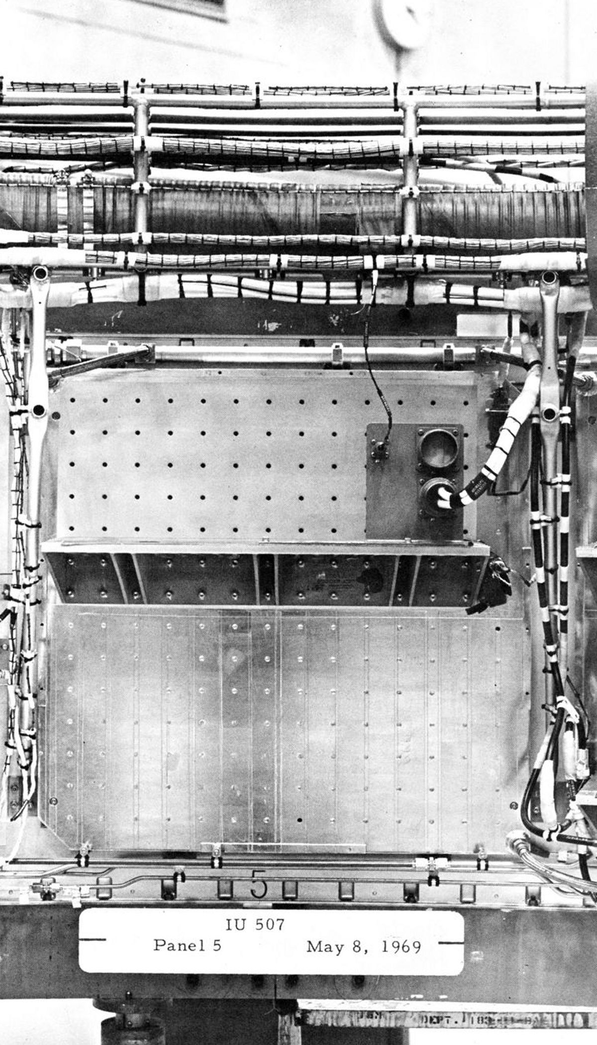
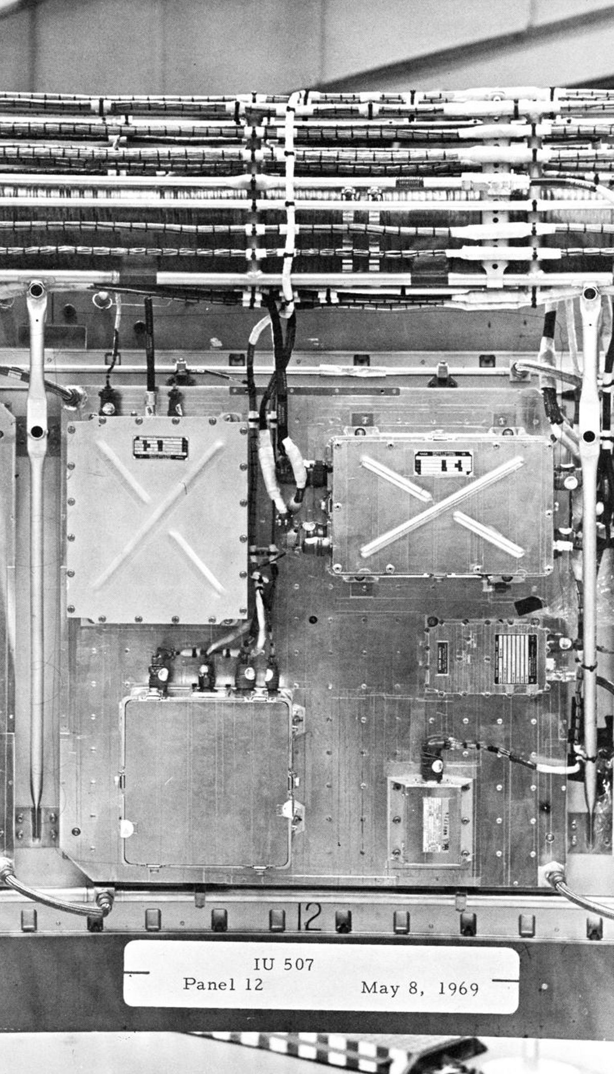
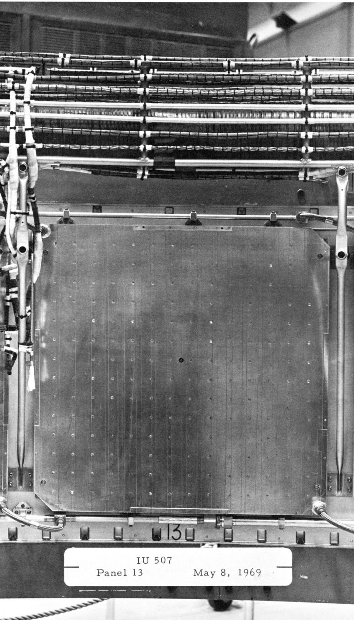
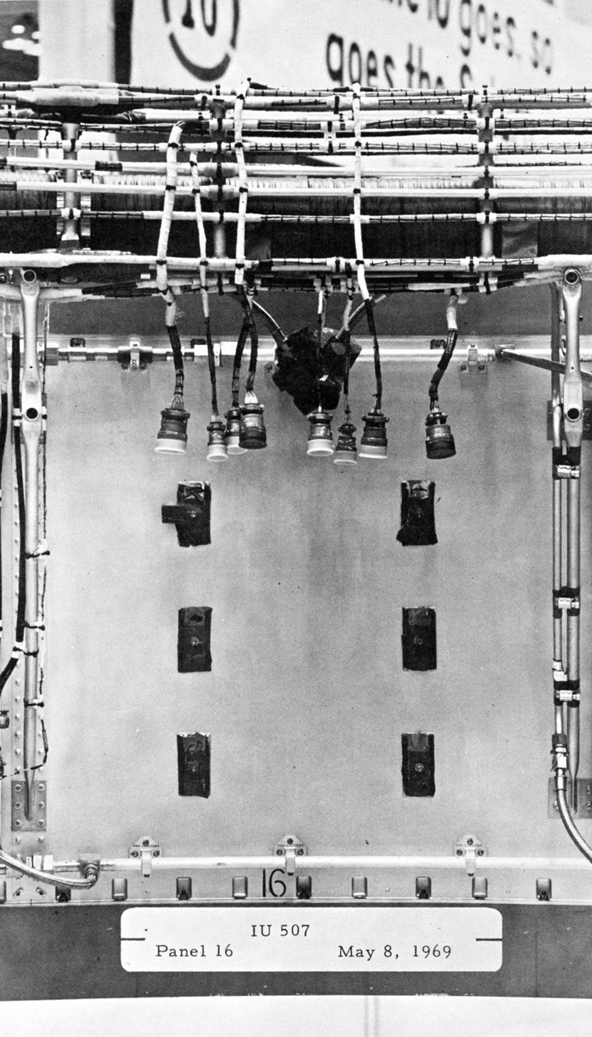
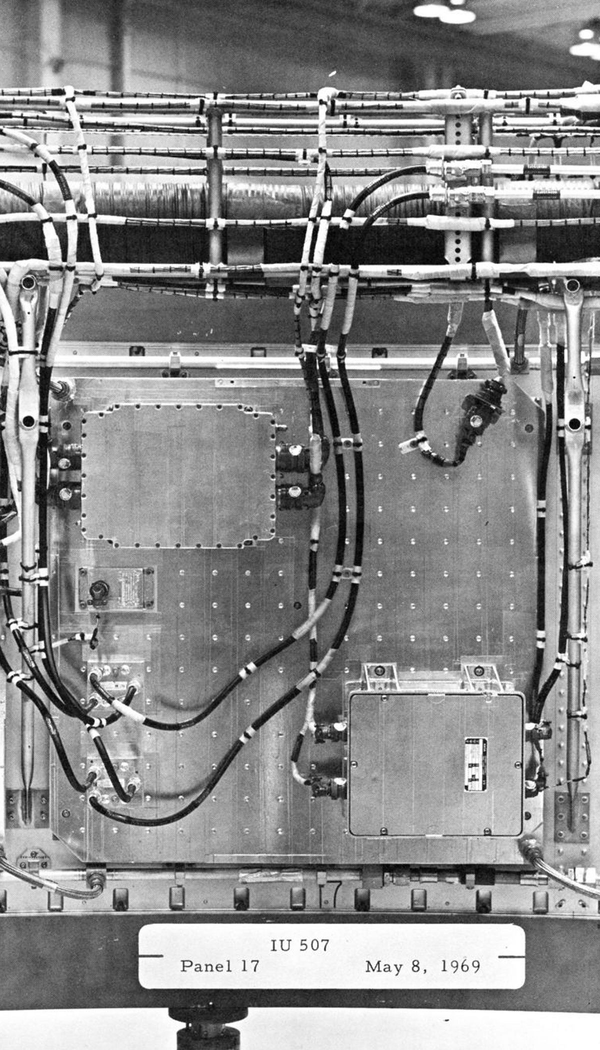
Left: Cross section "A" shows equipment mounting pads bolted and bonded to the honeycomb structure, a method used for equipment not mounted on a cold plate. Bolts were inserted through the honeycomb core with their ends and nuts protrudeing through the outside surface. Cross section"B" shows a thermal conditioning cold plate bolted to brackets that were bolted on the honeycomb structure. The bolts went through the honeycomb core with the bolt heads protruding through the outer surface. Cross section "C" shows the cable tray supports bolted to inserts, which were potted in the honeycomb core at the upper and lower structure edges. |
The IU structure was fabricated of an aluminum alloy honeycomb sandwich material with extruded aluminum channels bonded to the honeycomb top and bottom edges. The original design collapsed during structural testing, but thicker material in some key spots fixed the problem without altering the fundamental design. The IU structure had a high strength-to-weight ratio, acoustical insulation, and thermal conductivity. The cylinder was manufactured in three 120° segments (access door, flight control computer and ST-124-M3 segments) joined by splice plates into an integral structure. The access door segment featured both an umbilical door and a personnel access door, which was removable at any time prior to flight and also carried flight loads. Cold plates attached to the IU inner surface allowed electrical/electronic equipment mounting and provided thermal conditioning.
 |
 |
 |
 |
 |
 |
 |
 |
 |
 |
 |
 |
 |
 |
 |
 |
| 1 | 2 | 3 | 4 | 5 | 6 | 7 | 8 |
 |
 |
 |
 |
 |
 |
 |
 |
| 9 | 10 | 11 | 12 | 13 | 14 | 16 | 16 |
 |
 |
 |
 |
 |
 |
 |
 |
| 17 | 18 | 19 | 20 | 21 | 22 | 23 | 24 |
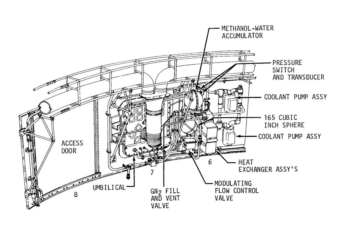
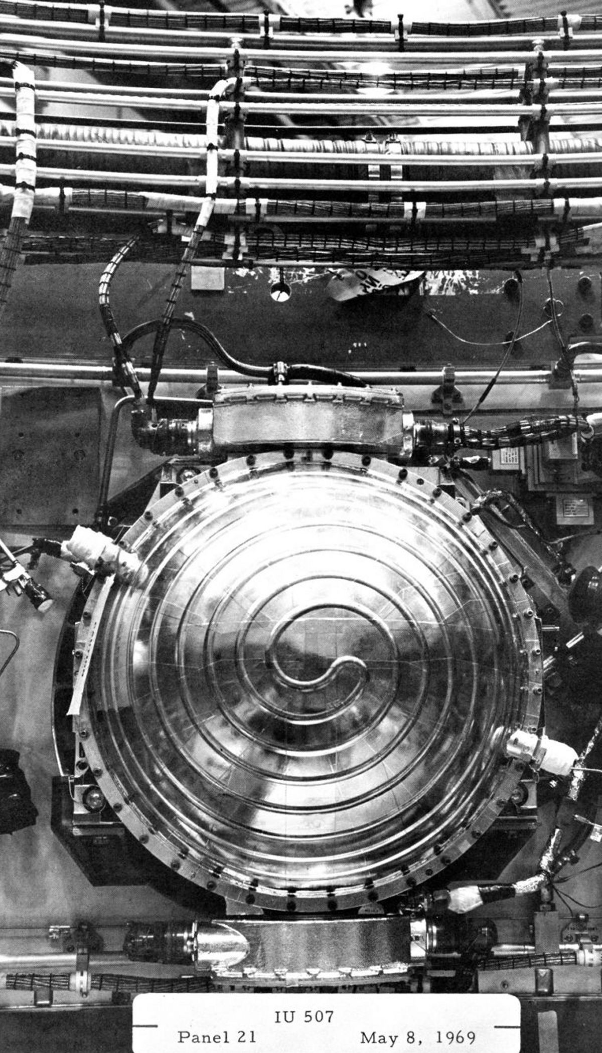
Environmental Control System
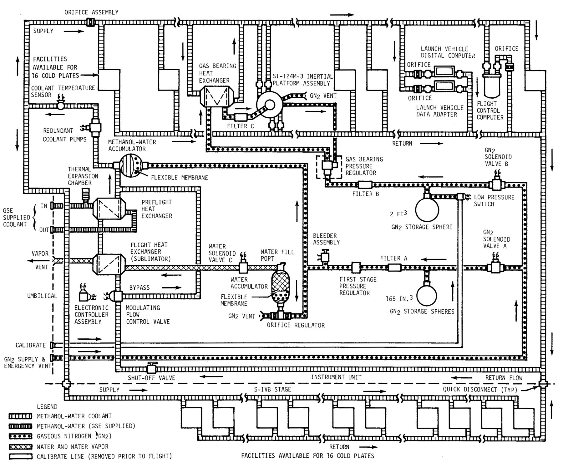 TCS Flow Diagram |
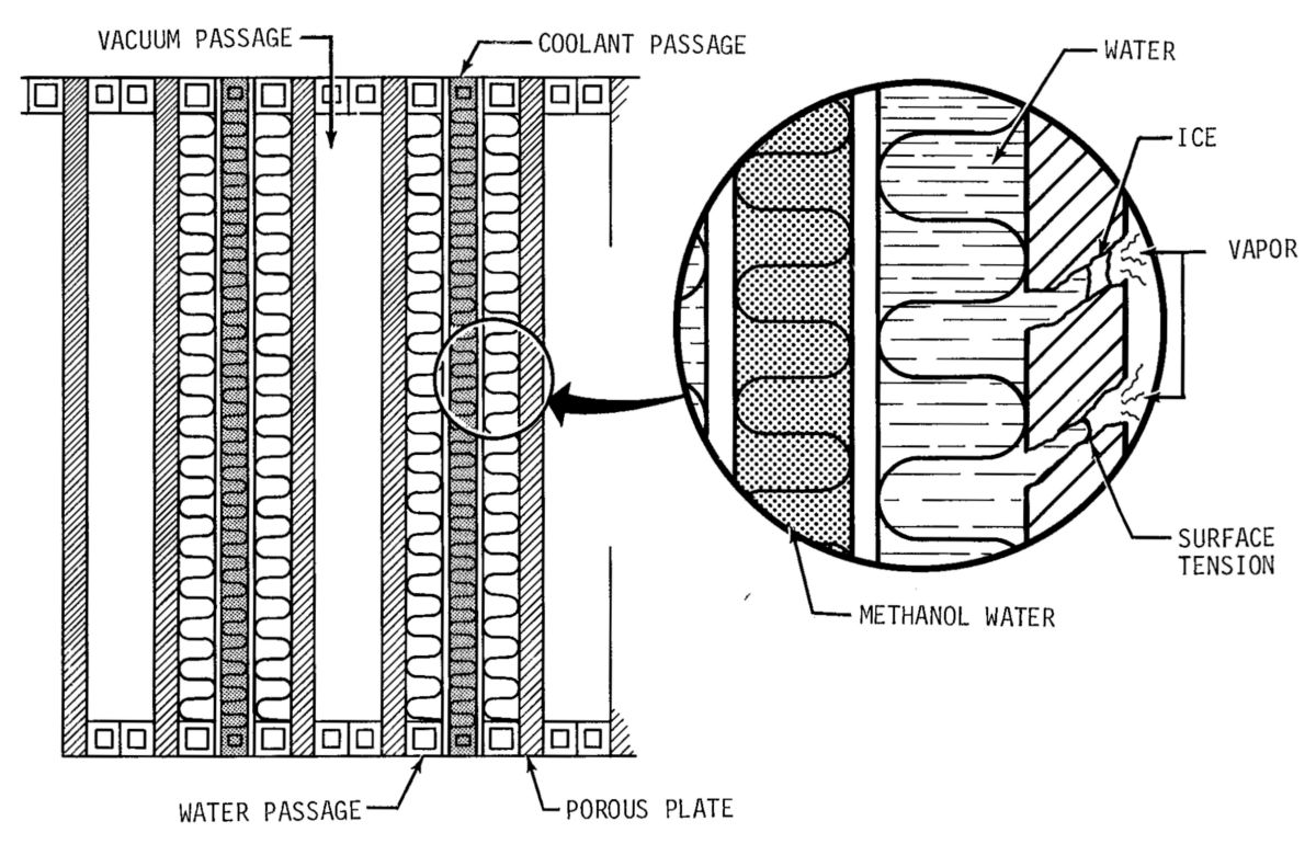 TCS Sublimator |
Thermal conditioning panels (cold plates), located in both the IU and S-IVB stage, contained a grid pattern of tapped bolt holes for component mounting flexibility; each could dissipate a minimum of 420 watts.The TCS employed two heat exchangers, one for preflight operations using a GSE-supplied circulating coolant, and one for flight operations that used sublimed demineralized water for cooling. The manifold, plumbing, and both accumulators were manually filled during the prelaunch preparations. Two accumulators absorbed pressure and thermal expansion fluctuations, and served as reservoirs that replaced expended fluids. There were flexible diaphragms in each accumulator, backed by low pressure GN2.
A 60% methanol, 40% demineralized water mixture originally served the TCS main coolant loop. Then IBM started having problems with Launch Vehicle Digital Computer (LVDC) and Launch Vehicle Data Adapter (LVDA) logic failures. A close examination of the failing unit logic devices (ULD) revealed that the resistor values had changed. The resistors were made from indium oxide of a certain thickness whose dimensions had been trimmed to provide the correct resistance after the firing operation. Somehow the indium oxide's resistivity was changing. Careful study showed that the indium oxide was being reduced by elemental hydrogen coming from an unknown source. Further study showed that the methanol-water coolant was outgassing hydrogen, which was migrating through pores in the Teflon coolant hose that connected the LVDC memory modules to the logic modules. The methanol-water was replaced by a synthetic, non-outgassing coolant and the problem was solved.
During TCS operation, coolant was circulated through a closed loop by redundant electrically-driven pumps that took coolant from the heat exchanger via the accumulator, through a temperature sensor and orifice that diverted part of the coolant to the S-IVB cold plates and part to the cold plates, gas bearing heat exchanger, inertial platform, LVDC/LVDA and flight control computer (FCC) in the IU. Return flow passed through a flow controller that, based on coolant temperature, regulated coolant flow through the heat exchangers.
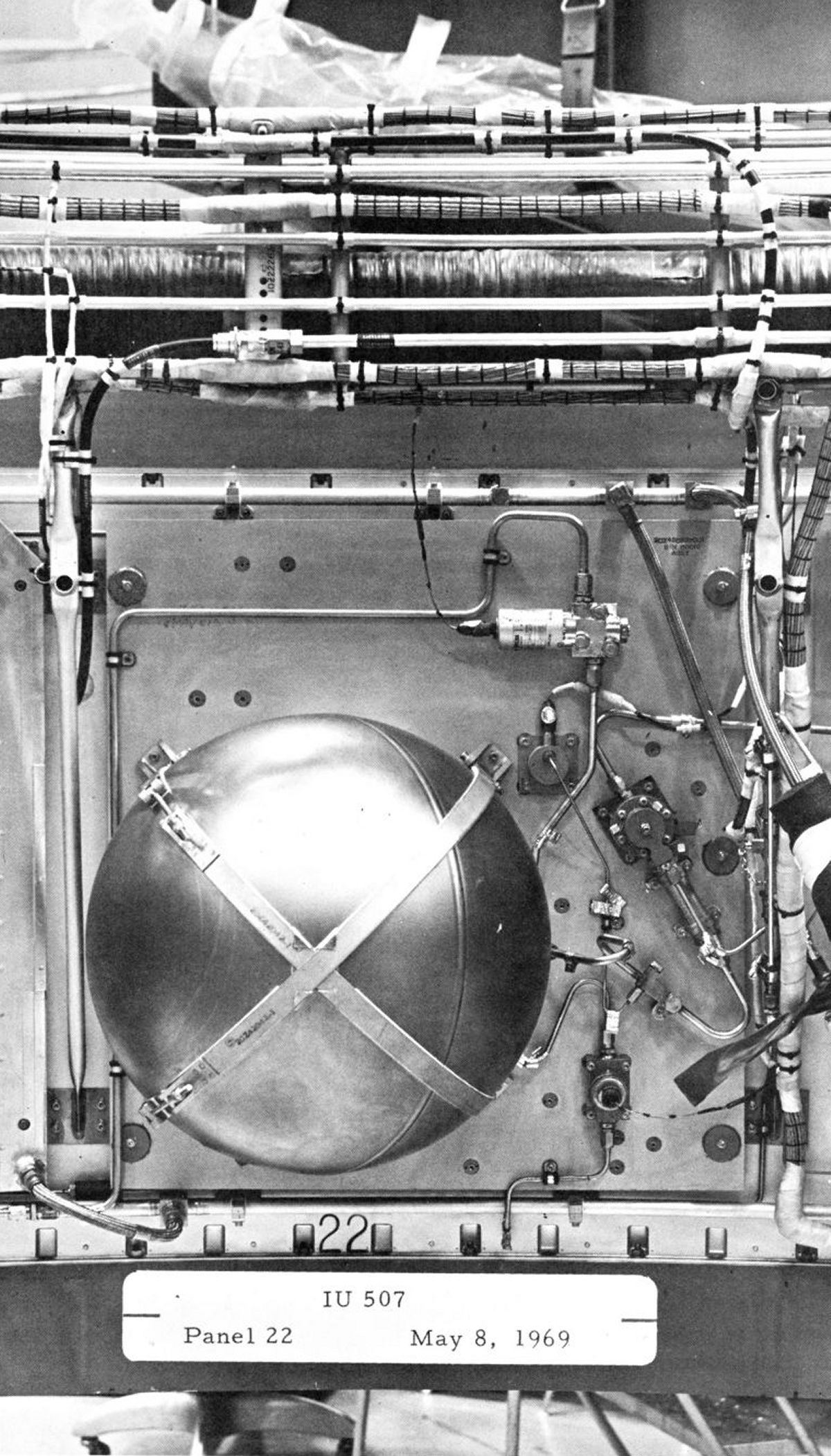
Prior to flight, when the ambient pressure was one atmosphere, the sublimator heat exchanger's water flow was blocked by a solenoid valve and GSE cooled the closed-loop coolant. About 180 seconds after liftoff, the water solenoid valve and the sublimator became active. Between GSE disconnect and sublimator activation, coolant, cold plate and equipment housing thermal mass prevented equipment overheating. The sublimator consisted of porous plates through which water easily flowed but froze when it met the low-pressure/low-temperature space environment; the resulting ice blocked the pores. As the equipment generated heat and coolant temperature rose, its heat transferred within the sublimator to the demineralized water. As the water temperature rose, ice in the pores to sublimed and the vapor vented overboard. As heat flow decreased, ice plugs again formed in the pores, decreasing water flow. Thus, the sublimator system was self-regulating. GN2 for the coolant and water accumulators was stored in a 165 in³ sphere in the IU at 3,000 psig. The sphere was filled through the umbilical by high pressure GN2. A solenoid valve controlled GN2 flow into the sphere, and a pressure transducer indicated when the sphere was pressurized. GN2 leaving the sphere passed through a filter and pressure regulator that reduced its pressure to 15 psig. An orifice regulator further reduced the pressure at the accumulators to 5 psig, the l0 psia differential being vented into the IU.
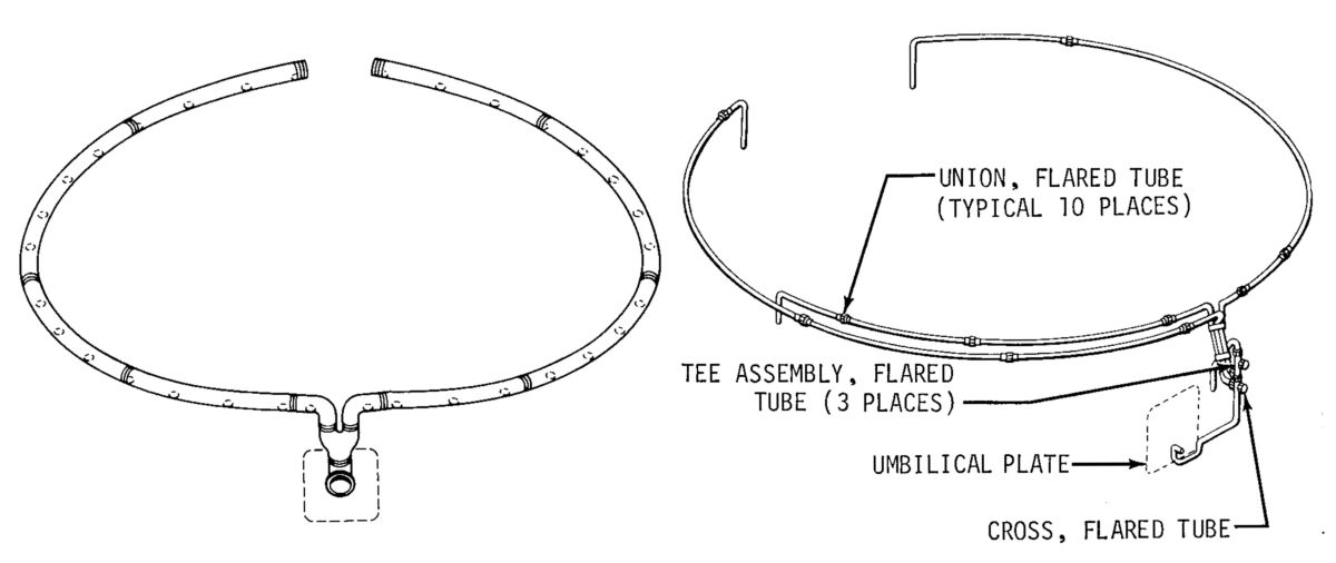 L: Air/GN2 Purge System R: Hazardous Gas Detection System |
The preflight air/GN2 purge system was a flexible duct located above the IU payload interface. The system distributed ground supplied, temperature and pressure regulated, filtered air or GN2 through openings in the duct. Air was used for ventilation during preflight, but during fueling and thereafter, inert GN2 prevented accumulation of a hazardous atmosphere.
Gas Bearing Supply ‑ GN2 for the ST-124-M3 stable platform was stored in a two cubic foot sphere in the IU, at a pressure of 3,000 psig. This sphere was filled through the umbilical by high-pressure GN2 under control of the IU pneumatic console. A low pressure switch monitored the sphere and if pressure fell below 1,000 psig, the ST-l24-M3 stable platform was shut down to preclude gas bearing damage. GN2 leaving the sphere passed through a filter and pressure regulator that reduced pressure to a level suitable for gas bearing lubrication. Gas bearing pressure was applied as a control pressure to the regulator, thus providing a constant pressure across the gas hearing. From the main regulator, GN2 flows through a heat exchanger where its temperature was stabilized, through another filter and on to the gas bearing. Spent gas was vented into the IU.
The hazardous gas detection system monitored the presence of hazardous gases in the IU and S-IVB stage forward compartments during vehicle fueling. The monitoring operation was continuous from the start of vehicle fueling to umbilical disconnect at liftoff. Four open-ended tubes originated between IU panels 1 and 2, 7 and 8, 13 and 14, and 19 and 20 merged and were connected to a quick-disconnect coupling. GSE hazardous gas detection equipment extracted samples, which were monitored for the presence of hazardous gases.
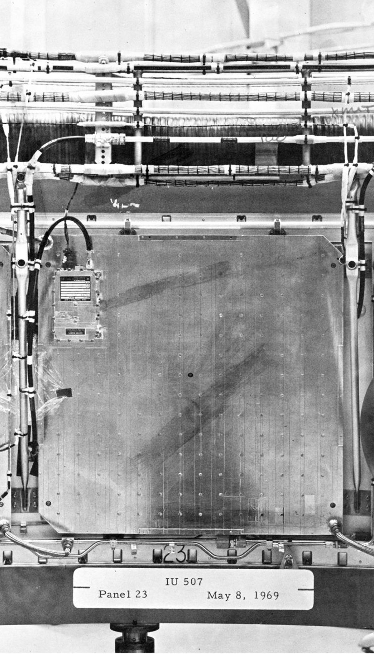
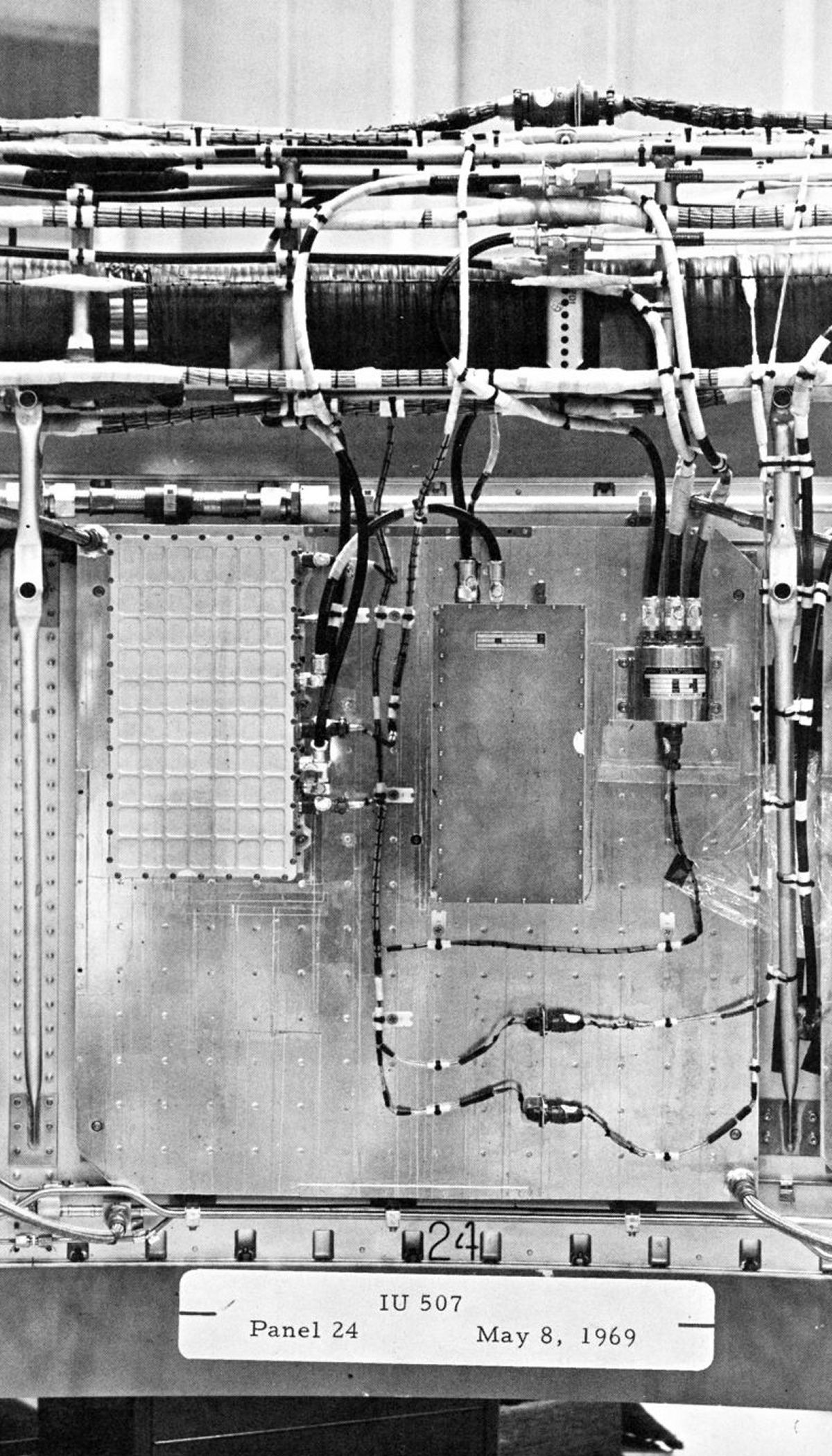
 Electrical Power System |
Electrical Power Systems
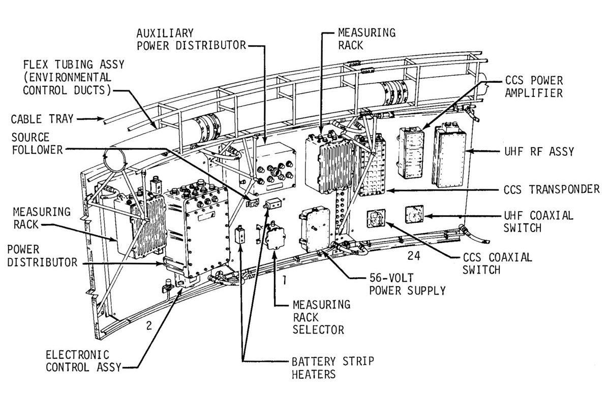
Primary IU flight power was supplied by 28 (± 2) VDC silver zinc batteries. Prelaunch primary power was supplied by GSE. Solid-state DC-to-AC converters supplied IU AC power. IU power distribution was via power distributors, which were junction boxes and switching circuits.
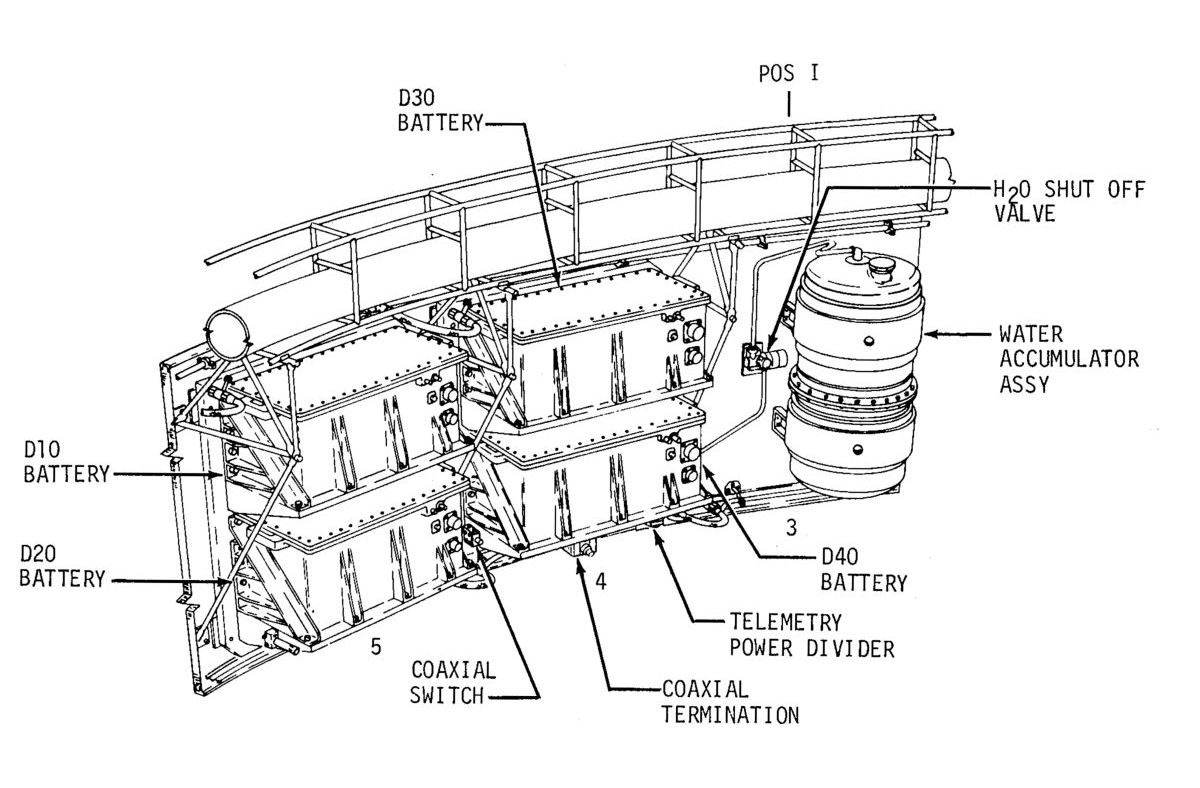
Batteries ‑ Physically identical silver-zinc primary flight batteries were installed in the IU during prelaunch preparations. Each battery was connected to a separate power distributor bus. Flight components were connected so as to evenly distribute the electrical load between batteries. Silver-zinc batteries were very efficient, with ampere-hour ratings about four times better than lead-acid or nickel-cadmium batteries of the same weight. Silver-zinc battery low-temperature performance was also substantially better.
Power Converters ‑ The IU electrical power systems contained a 56-volt power supply and a 5-volt measuring voltage supply. The 56-volt power supply furnished power to the ST-124-M3 platform electronic assembly and the accelerometer signal conditioner. It was a DC-to-DC converter with a magnetic amplifier control unit. It converted unregulated 28 VDC to regulated 56 VDC. The 56-volt power supply was connected to the platform electronic assembly through the power and control distributors. The 5-volt measuring voltage supply converted unregulated 28 VDC to a closely regulated 5 (± .005) VDC for use throughout the IU measuring system. This regulated voltage was used as excitation for measurement sensors (transducers), and as a reference voltage for inflight calibration of certain telemetry channels. Like the 56-volt supply, it was a DC-to-DC converter.
Distributors ‑ The IU distribution system consisted of two measuring distributors, one control distributor, one Emergency Detection System (EDS) distributor, one power distributor and two auxiliary power distributors.
The measuring distributors collected all measurements that were transmitted by the IU telemetry system, and directed them to their proper telemetry channels. These measurements were obtained from instrumentation transducers, functional components, and various signal and control lines. The measuring distributors also distributed the 5-volt measuring voltage supply output throughout the measuring system. The measuring distributors could change the selection of measurements monitored by the telemetry system, thereby transferring measurements to channels previously allotted to expended functions (i.e., second and third stage to first stage measurements after first-stage burnout). Without this switching, such channels would be wasted for the remainder of the flight.
The control distributor provided auxiliary 28 VDC power to small current loads and distributed 56 VDC to the ST-124-M3 inertial platform assembly during prelaunch checkout and for testing various guidance, control, and EDS functions as requested by the launch vehicle data adapter (LVDA) through the switch selector.
The EDS distributor provided the only electrical link between the spacecraft and the LV. All LV EDS signals passed through logic circuits in the EDS distributor. Output signals from these logic circuits were fed to the spacecraft and IU telemetry. Spacecraft EDS signals were routed back through the IU EDS logic circuits before being sent to the S-IVB, S-II, and S-IC stages.
The power distributor switched all IU 28 VDC power, from GSE before flight and from the batteries during flight. The power distributor also provided command and measurement signal paths between the ESD and IU components, as well as connecting IU component power and signal return lines to the IU single-point ground and umbilical supply return bus. These return lines were connected to the common bus in the power distributor, directly or indirectly, through one of the other distributors.
Two auxiliary power distributors supplied 28 VDC power to small current loads. So that current loads on each battery were evenly distributed, both auxiliary power distributors received 28 VDC from each power distributor battery bus. Auxiliary power distributor relays provided ON/OFF power control for IU components during the prelaunch checkout and while in flight. These relays were controlled by the GSE and by the switch selector.
All IU grounding was referenced to the LV outer skin by means of hard wires routed from the power distributor COM bus to a grounding stud attached to the LV skin. All COM busses in the various other distributors were wired back to the COM bus in the power distributor. This provides for a single point ground. Equipment boxes were grounded by direct metal-to-metal contact with cold plates or other mounting surfaces common to the LV skin. Most cabling shields were grounded to a COM bus in one of the distributors. However, where shielded cables run between equipment boxes, and not through a distributor, only one end of the shield would be grounded. During prelaunch operations, the IU and GSE COM busses were referenced to earth ground. To ensure the earth ground reference until after all umbilicals were ejected, two, single wire grounding cables were connected to the IU below the umbilical plates. These were the final conductors disconnected from the IU.
Emergency Detection System
EDS design was a coordinated effort of crew safety personnel from several NASA centers, with the EDS serving as one element of several crew safety systems. The EDS sensed developing conditions that could cause vehicle failure and reacted to these emergencies in one of two ways. If vehicle breakup was imminent, it started an automatic abort sequence. However, if the emergency situation was developing slowly and could be evaluated by the flight crew, the crew got a visual indications. Once an abort sequence was initiated, either automatically or manually, it was irrevocable and ran to completion.
Sensing elements (such as signal processing and switching circuitry), relay and diode logic circuitry, electronic timers and display equipment, all located in various places on the flight vehicle, comprised the EDS. Only EDS equipment located in the IU is discussed here. Nine (triple-redundant roll, pitch and yaw) EDS rate gyros in the IU monitor each of the three axes. The control signal processor powered the rate gyros and received inputs from them, which were processed and sent to the EDS distributor and to the FCC.
The EDS distributor was a junction box and switching device that furnished spacecraft display panels with emergency signals when emergencies existed. It also contained relay and diode logic for the automatic abort sequence. An electronic timer, activated at liftoff, produced an output 30 seconds later that energized relays in the EDS distributor that enabled multiple engine shutdown; this function was inhibited during the first 30 seconds of launch. Abort circuitry was also inhibited by the LV flight sequencing circuits through the IU switch selector. Such inhibiting was required prior to normal S-IC engine cutoff and other normal LV sequencing. While the automatic abort capability was inhibited, the flight crew had to initiate a manual abort, if an angular-overrate or two-engine-out condition arose.
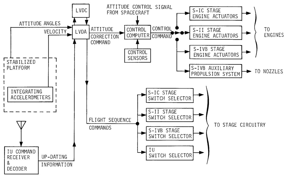 GNC Block Diagram |
Guidance, Navigation and Control (GNC)
A three-gimbal stabilized platform (ST-124-M3) provided a space-fixed coordinate reference frame for attitude control and for navigation (acceleration) measurements. Three integrating accelerometers, mounted on the gyro-stabilized platform inner gimbal, measured the three components of velocity resulting from vehicle propulsion. The accelerometer measurements were sent through the launch vehicle data adapter (LVDA) to the LVDC. In the LVDC, the accelerometer measurements were combined with the computed gravitational acceleration to obtain the vehicle's position and velocity. The LVDA was the input/output device for the LVDC, performing necessary signal processing for the LVDC.
According to the programmed guidance scheme, the LVDC determined the maneuvers required to achieve the desired trajectory. The instantaneous vehicle position and velocity were used as inputs. The result was the required thrust direction (guidance command) and the time of engine cutoff.
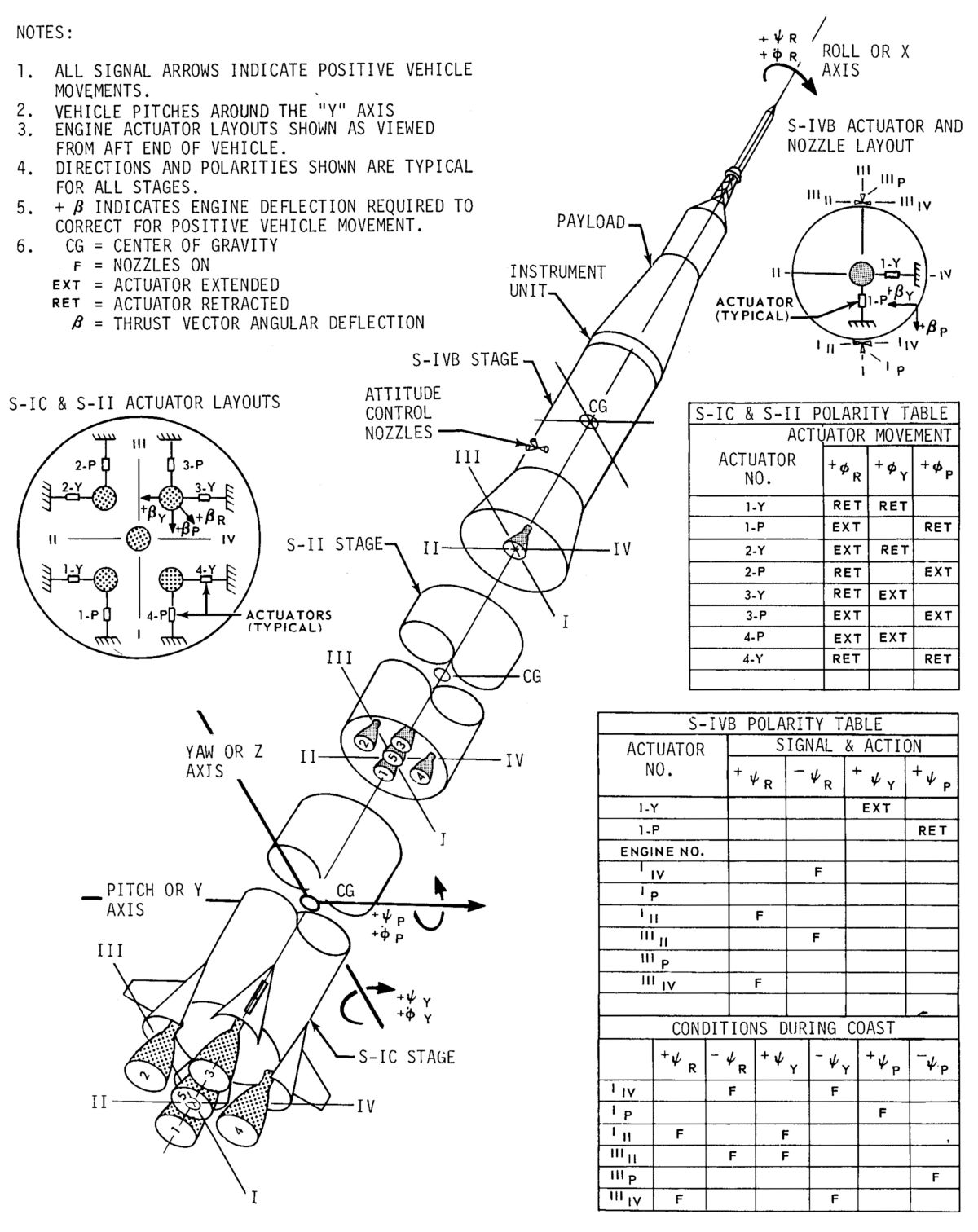
Launch vehicle control consisted of attitude control and discrete control functions. For attitude control, the LVDC compared the vehicle's instantaneous attitude with the desired vehicle attitude and produced attitude correction signals. The FCC combined these attitude correction signals with control sensor signals to generate the control commands for the engine actuators, which gimbaled the engines in to change the vehicle thrust vector. In the S-IC and S-II, the four outboard engines were gimbaled to control roll, pitch, and yaw. Since the S-IVB stage had only one engine, an auxiliary propulsion system (APS) controlled roll control during powered flight and roll, pitch and yaw during coast flight.
Ground stations could use an IU command system to update LVDC guidance information (position, velocity). The IU command system also provided a general capability of changing or inserting LVDC information.
 Navigation Scheme and Guidance Equation |
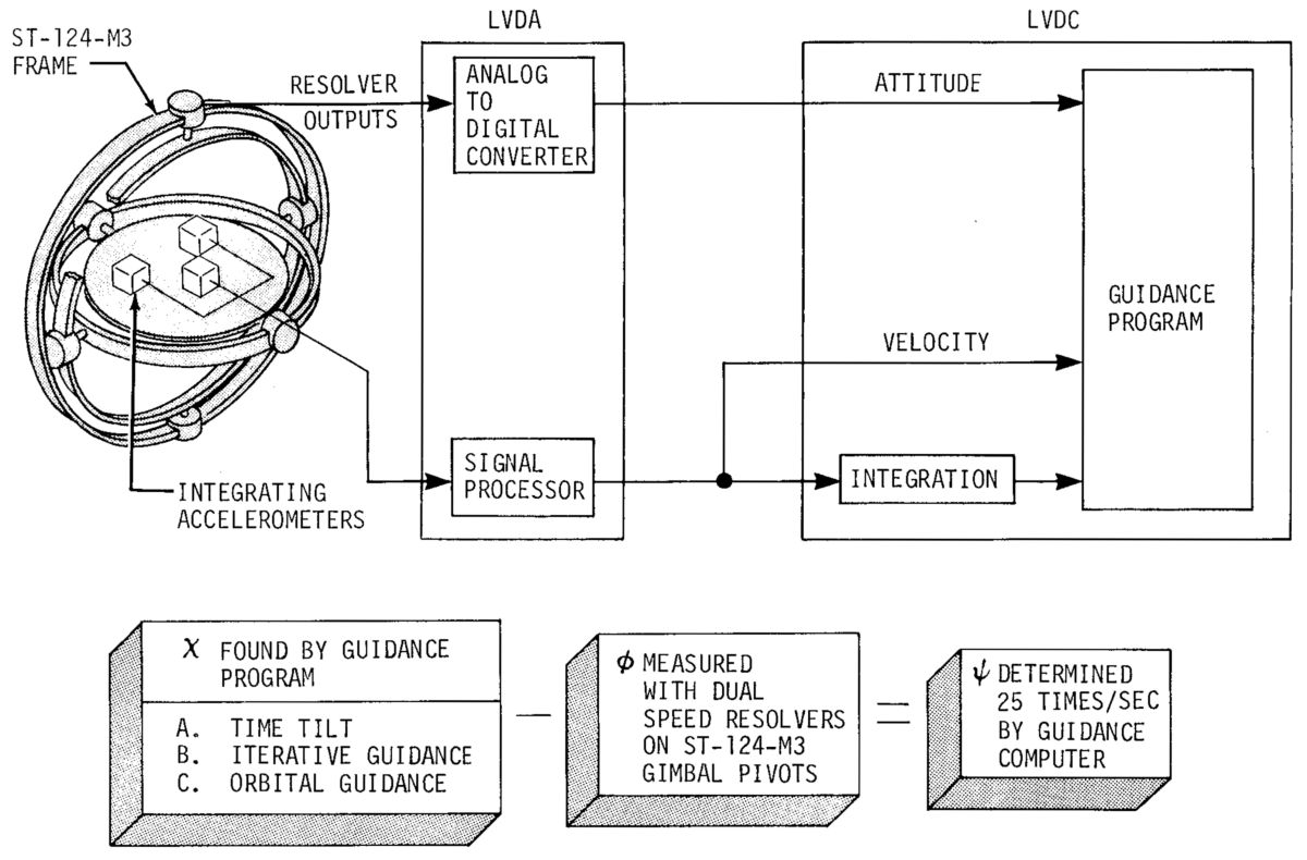
Launch vehicle guidance involved computing the necessary flight maneuvers to insert the spacecraft into the desired trajectory. The LVDC performed guidance computations using programmed guidance equations, which used navigation data and mission requirements as their inputs. These computations were a logical progression of computed formulae that had a guidance command as their solution. After the desired attitude was determined by the "best path" program, the guidance computations were reduced into the following equation: χ = φ- ψ where χ was the desired attitude, φ was the vehicle attitude, and ψ was the attitude error command
Powered Flight Navigation Scheme. Gimbal resolvers supplied analog platform position the LVDA where analog-to-digital converter digitized the data for use by the LVDC. Platform integrating accelerometers sensed acceleration components and mechanically integrated them into velocity. The LVDA digitized these data for the LVDC where initial velocity imparted by the spinning earth, gravitational velocity, and platform velocities were algebraically summed. This vehicle velocity was integrated by the LVDC to determine vehicle position. Since acceleration is the rate-of-change (derivative) of velocity and velocity is the rate-of-change of position (distance), velocity was the integral of acceleration, and position was the integral of velocity. Position was obtained by integrating acceleration twice.
Orbital Flight Navigation Scheme. During orbital coast flight, the navigational program continually computed the vehicle position, velocity, and acceleration from equations of motion based on vehicle conditions at orbital insertion. In orbit, LVDC navigation and guidance information could be updated via digital data transmission through the IU command and communications system (CCS). Additional navigational computations maintained vehicle attitude during orbit. These computations established a local vertical that was used as a reference for attitude control, which maintained the vehicle roll axis at 90° with respect to the local vertical.
 Control System Block Diagram |
 Saturn V Engines and Actuators |
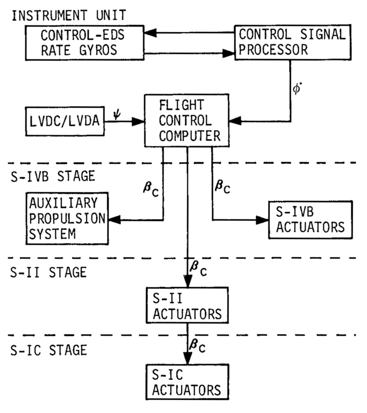
The control system maintained vehicle attitude by forming engine thrust vector control commands. The four outboard S-IB, S-IC and S-II engines, and the single S-IVB engine were gimbaled by hydraulic actuators. S-IVB roll control was via the APS. During orbital and translunar coast the S-IVB APS controlled vehicle attitude in all three axes. The control system accepted guidance computations in the form or attitude error signals from the LVDC/LVDA. These error signals were then combined with measured control sensor data, resulting in command signals for the various engine actuators and APS rockets. The final analog computations were performed by the FCC, which then routed control signals to the active stage engine gimbaling actuators and/or thrusters.
Control System Components
The control signal processor demodulated AC signals from the control-EDS rate gyros into DC analog signals required by the FCC. The control signal processor compared the triple-redundant rate gyro output signals and selected one each of the roll, pitch and yaw signals for the FCC. The control signal processor also supplied the control-EDS rate gyro package with control and reference voltages. EDS and digital data acquisition system (DDAS) rate gyro monitoring signals also originated within the control signal processor, thus accounting for the EDS portion of the control-EDS rate gyro name.
The FCC was an analog computer that converted attitude correction commands (ψ) from the LVDC/LVDA and angular change rates (φ) from the control-EDS rate gyros via the control signal processor into APS thruster nozzle and/or engine actuator commands. FCC filter networks limited excessive attitude correction commands from the LVDC to protect the vehicle structure. FCC output signals included command signals to the engine actuators (βc), command signals to the APS thrusters and telemetry that monitored internal operations.
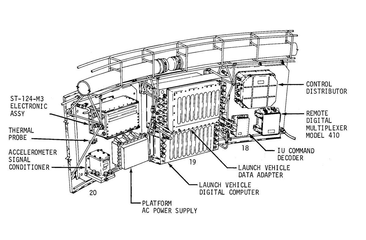
ST-124-M3 Inertial Platform Assembly
 ST-124-M3 Schematic |
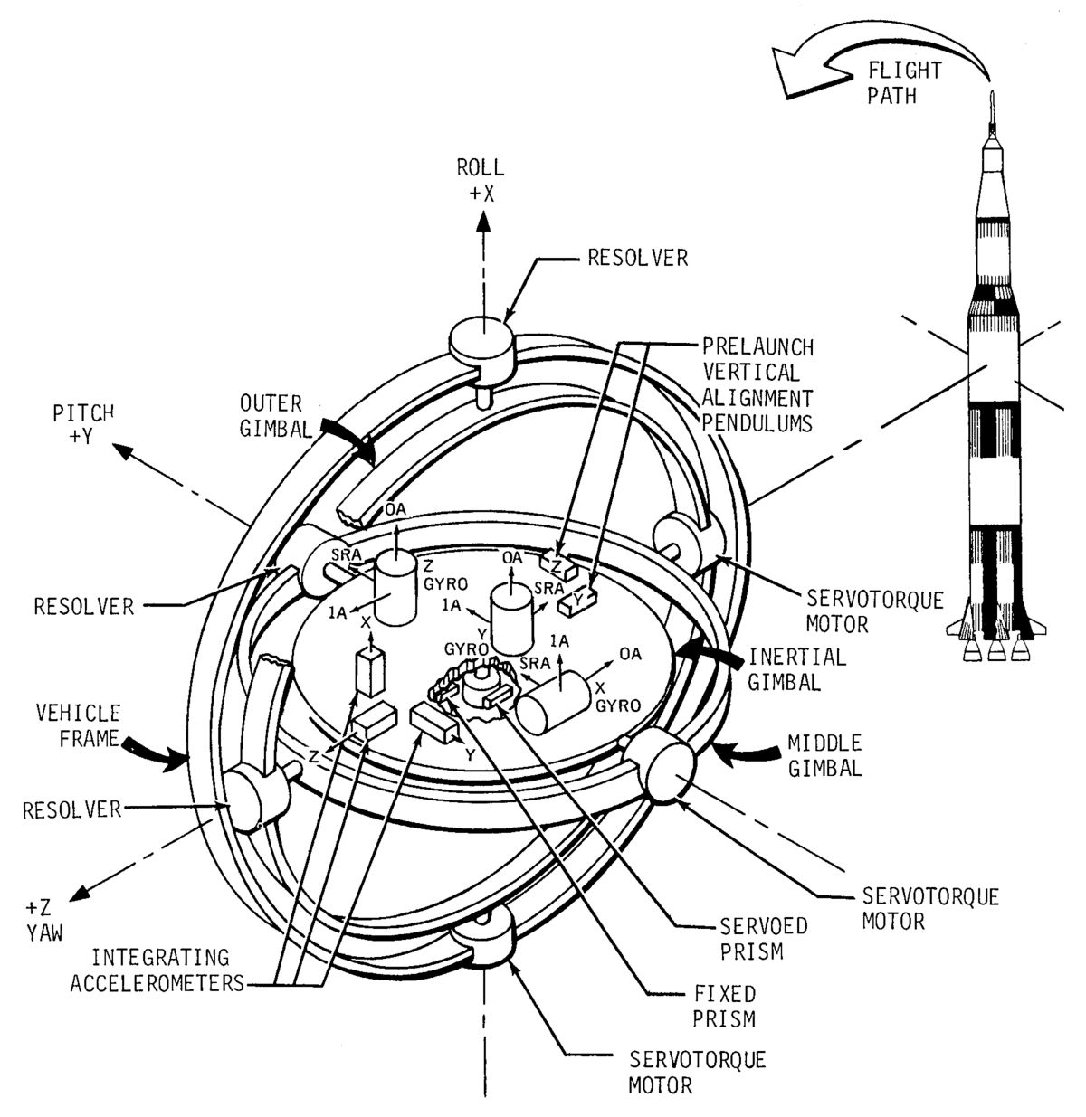
The ST-124-M3 gimbal configuration offered unlimited freedom about the X and Y axes, but was limited to ±45° about its Z axis (vehicle yaw at launch). Three single-degree-of-freedom gyroscopes had their input axes aligned along an orthogonal inertial coordinates system (X1, Y1 , and Z1) of the inertial gimbal. A signal generator, fixed to the output axis of each gyro, produced electrical signals proportional to torque disturbances. These signals were transmitted through the servo electronics, which terminated in the gimbal pivot servo-torque motors. The servo loops maintained the inner gimbal rotationally fixed in inertial space.
The inner gimbal had three pendulous integrating gyroscopic accelerometers, oriented along the inertial coordinates X1, Y1 , and Z1. Each accelerometer measuring head contained a pendulous, single-degree-of-freedom gyro. The rotation of the measuring head was a measure of acceleration along the accelerometer input axis. Since acceleration causes the accelerometer shaft to be displaced as a function of time, the shaft position (with respect to a zero reference) was proportional to velocity, and the accelerometer was referred to as an integrating accelerometer.
Vehicle attitude was measured with respect to the inertial platform, using 32:1 dual-speed resolvers located at the gimbal pivot points. These angle encoder outputs were digitized in the LVDA. During prelaunch, the ST-124-M3 platform was held aligned to the local vertical by a set of gas bearing leveling pendulums. The pendulum output was amplified in the platform and transmitted to the ground equipment alignment amplifier, which provided a signal to the torque drive amplifier, and then to the platform gyro torque generator. The vertical alignment system leveled the platform to an accuracy of ±2.5 arc-seconds.
The azimuth alignment was accomplished by means of a theodolite on the ground and two prisms on the platform, one fixed and one servo driven. The theodolite maintained the azimuth orientation of the movable prism while the computer computed a mission azimuth and programmed the inner gimbal to that azimuth. The laying system had an accuracy of ±5 arc-seconds. At approximately liftoff minus 17 seconds, the platform was released to maintain an inertial reference initiated at the launch point. At this time, the LVDC began navigation, using velocity accumulations derived from the ST-124-M3 inertial platform.
The ST-124-M3 platform electronic assembly (PEA) contained the electronics for inertial gimbal and accelerometer stabilization. Switching electronics for controlling platform system power and checkout functions were also located in the ST-124-M3 platform electronic assembly.
The ST-124-M3 platform AC power supply furnished three-phase 26-VAC 400-Hz power to run the gyro rotors and provided single-phase 20 VAC 4.8 kHz, 1.02 kHz and 1.6 kHz excitation for the platform gimbal synchros. The accelerometer signal conditioner accepted velocity signals from the accelerometer optical encoders and shaped them before they were passed on to the LVDA/LVDC. Each accelerometer required four shapers: a sine shaper and cosine shaper for the active channel, and a sine shaper and cosine shaper for the redundant channels. Also included were four buffer amplifiers for each accelerometer, one for each sine and cosine output. Accelerometer outputs provided telemetry and ground checkout signals in addition to outputs to the LVDA.
LV Digital Computer and LV Data Adapter
The LVDC/LVDA combination formed an electronic digital computer system. The LVDC did the computing; the LVDA did all input/output, meaning that any signal to or from the computer went through the LVDA. The LVDC and LVDA were involved in prelaunch checkout, guidance and navigation computations, vehicle sequencing and orbital checkout. The LVDC, a general purpose computer, processed data under stored-program control. Data was processed serially in two arithmetic sections that could operate concurrently. Addition, subtraction, and logical operations were performed in one arithmetic section; multiplication and division in the other.
A random-access, ferrite-core memory with separate data and instruction addressing controls, capable of either a simplex or duplex operation, allowed memory modules to be operated in pairs with the same data being stored in each module. Readout errors in one module were corrected by using data from its mate to restore the defective location. In simplex operation, each module contained different data, doubling the memory capacity. Simplex operation came at the cost of decreased reliability since read errors were uncorrectable. Static registers composed of latches and shift registers composed of delay lines and latches, furnished temporary storage. Triple modular redundancy with voting increased logic section reliability by detecting and correcting logic module errors.
LVDC and LVDA logic circuits were built from several different types of Unit Logic Devices (ULD), a term IBM used for its particular brand of diode-transistor logic implementing a logical AND-OR-INVERT function. ULDs began as a 0.3" square alumina substrate onto which circuit wiring and resistor patterns were silk screened. After firing, planar transistors and diodes were added and the substrate packaged as a 14-pin flat-pack with 12 leads active. Up to 70 ULDs could be assembled to the outer surfaces of two multilayer interconnection boards sandwiched over a magnesium-lithium alloy frame; IBM called these assemblies "pages". A 98-pin connector on the page bottom interfaced with the LVDC or LVDA backplane.
Flight Program
A flight program stored in LVDC memory controlled LVDC operation from before liftoff until the launch vehicle's mission end. The flight program oversaw the launch, guidance, navigation, attitude control, event sequencing, data management, ground command processing, and hardware evaluation. Five elements comprised the flight program: the powered flight major loop, the orbital fight program, the minor loop, interrupts, and telemetry. The powered flight major loop performed guidance and navigation calculations, timekeeping, and all repetitive non-interrupt functions.
The orbital flight program consisted of an executive routine that evaluated IU equipment during orbit, and a time-sharing telemetry routine that operated when the vehicle was over receiving stations. The orbital flight program also performed all navigation, guidance, and timekeeping computations on an interrupt basis, keyed to the minor loop. The minor loop sampled the platform gimbal angle and accelerometer values and performed control computations. Since the minor loop was essential to vehicle control, it executed at 25 Hz during powered flight and at 10 Hz when coasting.
Prelaunch and Initialization — The LVDC was under ground control computer (GCC ) control until a few minutes before launch. At T-8 minutes, the GCC issued a prepare-to-launch (PTL) command to the LVDC. The PTL routine executed an LVDC/LVDA self-test program and telemetered the results. It monitored accelerometer inputs, calculated the platform-off-level indicators, and telemetered accelerometer outputs and time. It also performed reasonableness checks on particular discrete inputs and alerts. It interrogated the LVDC error monitor register, zeroed all flight control system ladder outputs (which kept the engines in a neutral position for launch), processed the Guidance Reference Release (GRR) interrupt, transferred LVDC control to the flight program, and sampled platform gimbal angles.
At T-22 seconds, the launch sequencer issued a GRR alert signal to the LVDC and GCC. At T-l7 seconds, a GRR interrupt signal was sent to the LVDC and GCC. With the receipt of this signal, the PTL routine transferred LVDC control to the flight program. When the LVDC received the GRR interrupt the LVDC set time base zero (T0), gimbal angles and accelerometer values were sampled and stored for use by flight program routines, time and accelerometer readings were telemetered, all flight variables were initialized, and the GCC was signaled that the LVDC was under flight program control. During the time period between GRR and liftoff, the LVDC began to perform navigational calculations, and processed the minor loops. At T-8.9 seconds, the engine ignition command was issued. At T-0, liftoff occurred, and a new time base (T1) was initiated.
The powered flight major loop contained the guidance and navigation calculations, timekeeping, and other repetitive flight program operations. The accelerometer processing routine accumulated velocities as measured by the inertial platform and detected velocity measurement errors through "reasonableness" tests. The boost navigation routine combined gravitational acceleration with measured platform data to compute position and velocity. The pre-iterative (time-tilt) flight program guidance routine performed from GRR until S-IC burnout. The guidance commands issued during the time-tilt phase were functions of time only. This open loop guidance program phasedid not involve vehicle dynamics or influence guidance commands. When the launch vehicle cleared the mobile launcher, the range-tilt program first initiated a roll maneuver that aligned the vehicle with the proper azimuth. Thereafter, roll and yaw commands remained at zero, and the vehicle was gradually pitched about the vehicle's Y axis to its predetermined boost heading. Rate limiting prevented the flight control system from maneuvering the LV at rates exceeding safe limits. The iterative guidance mode (IGM routine), or "path adaptive" guidance, commenced after second stage ignition, and continued until the end of S-IVB first burn. Cutoff occurred when earth orbit velocity had been reached. IGM was used again during S-IVB second burn. IGM was based on optimizing techniques, using the calculus of variations to determine a minimum propellant flight path that satisfied mission requirements. Since the IGM considered vehicle dynamics, it was closed loop guidance.
Interrupt routines permitted interruption of normal program flow to process higher-priority time-sensitive work; an interrupt could occur at any time. When an interrupt occurred, LVDC control was transferred to a special interrupt routine that identified the interrupt source, performed the necessary actions, and then returned to the point in the normal program where the interrupt occurred.
A programmed telemetry feature allowed monitoring LVDC and LVDA operations. The telemetry routine transmitted program-specified data to the ground via IU telemetry equipment. In orbit, telemetry data was stored when the vehicle was not within range of a ground receiving station. This operation, called data compression, allowed the stored data to be transmitted on a time-shared basis with real-time telemetry when range conditions were favorable.
Discrete Backups — Certain discrete events were essential to the flight program because they periodically reset the computer time base that referenced for all sequential events. These significant time base events were T1 = Liftoff (L0), T2 = S-IC enter engine cutoff (CECO), T3 = S-IC outboard engine cutoff (OECO), T4 = S-Il cutoff, T5 = S-IVB cutoff (boost phase), T6 = S-IVB restart, and T7 = S-IVB cutoff (orbital phase)
Since switch selector outputs were a function of time (relative to one of the time bases);, no switch selector output could be generated if a discrete signal was missed. A programmed backup routine was provided to circumvent such a failure. The discrete backup routine simulated these critical signals if they did not occur when expected. In the cases of LO and CECO special routines established a double safety check; motion as well as time were confirmed before a backup discrete was issued. For LO, the backup routine ran 17.5 seconds after GRR; if vertical acceleration exceeded 6.544 ft/sec² for four computation cycles, the vehicle was assumed to be airborne and the liftoff discrete was issued. For CECO, an assurance was made than an on-the-pad S-II stage firing could not occur if T1 was accidentally set. Before T2 was initiated, velocity along the downrange axis had to be at least 500 m/sec.
Mode and sequence control involved most of the launch vehicle electrical/electronic systems as managed by switch selectors and associated circuitry. The LVDC caused certain launch vehicle electrical/electronic systems to operate in particular modes, where each mode consisted of a predetermined event sequence. The LVDC also generated appropriate discrete signals such as engine ignition, engine cutoff, and stage separation. Mode selection and initiation was accomplished by an automatic LVDC internal command, an external command from ground checkout equipment, the IU command system, or by the spacecraft flight crew. The mode and sequence control scheme flexibility assured that no hardware modification were required for mode and flight sequence changes. The changes were accomplished by changing program instructions in the LVDC's memory.
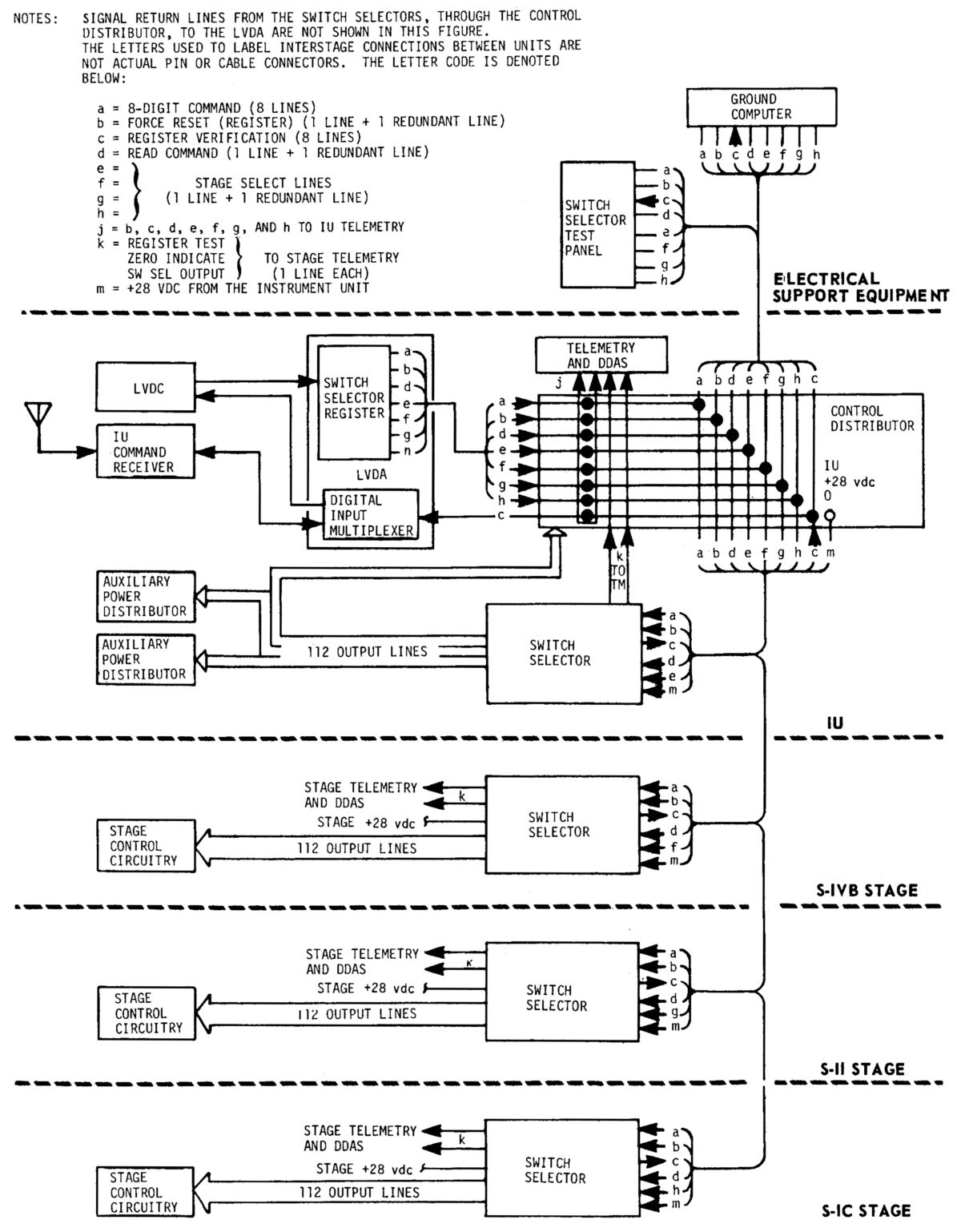 Switch Selectors |
Switch Selectors — Many LVDC-controlled sequential launch vehicle operations were performed through a switch selector in each stage. The switch selector decoded digital flight sequence commands from the LVDC/LVDA, and activated the proper stage circuits to execute the commands. Switch selector outputs drove relays either in the units affected or in the stage sequences. Each switch selector could activate 112 different stage circuits, one at a time. The selection of a particular stage switch selector was accomplished through a flight sequence command code that was decoded by stage switch selectors, greatly reducing the number of interface lines between stages, and increasing the flexibility of the system with respect to timing and sequence. In the launch vehicle, which contained four switch selectors, 448 different functions could be controlled using only 28 lines from the LVDA. Flight sequence commands could be issued at time intervals of 100 milliseconds.
Switch selectors were divided into sections in order to maintain power isolation between vehicle stages. The input sections (relay circuits) of each switch selector received their power from the IU. The output sections (decoding circuitry and drivers) received their power from the stage in which the switch selector was located. The inputs and outputs were coupled together through a diode matrix. This matrix decoded the 8-bit input code, and activated a transistorized output driver, thus producing a switch selector output. LVDA switch selector register output signals, with the exception of the 8-bit command, were sampled at the IU control distributor and sent to IU PCM telemetry. Each switch selector also provides three outputs to the telemetry system within its stage. The switch selector executed flight sequence commands given by the 8-bit code or by its complement. This feature increased reliability and permitted system operation despite certain LVDA switch selector register, line drivers, interface cabling, or switch selector relay failures. Flight sequence commands were stored in the LVDC memory, and were issued according to the flight program. When a programmed input/output instruction was given, the LVDC loaded the 15-bit switch selector register with the computer data. The LVDA forwarded this command to the appropriate switch selector, which returned the command's complement, allowing verification that the command had been received and understood by the switch selector. If not, a reset command was issued and the process repeated.
The Saturn V Operation Sequence started during the prelaunch phase at approximately T-24 hours when GSE electrical power was applied to all launch vehicle stages. Prelaunch sequencing was controlled from the launch control center/mobile launcher complex, with both manual and automatic control to check out launch vehicle functions. Once umbilicals were disconnected, the sequencing was primarily controlled by the LVDC flight program. Since flight sequencing was time phased, the sequencing operation was divided into seven primary time bases, described previously.
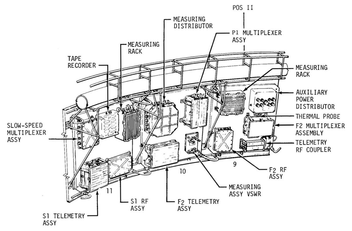
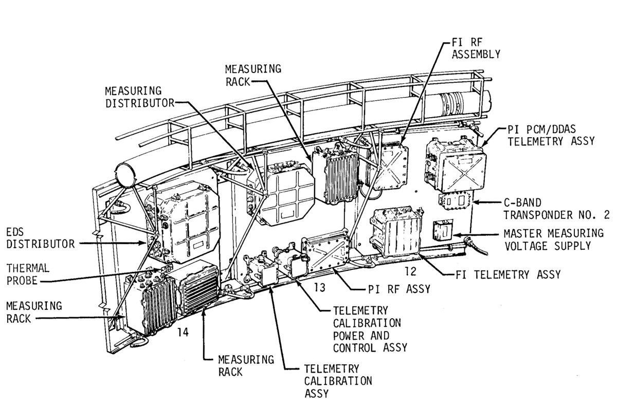
Measurements And Telemetry
 Measurement Summary |
IU instrumentation consisted of a measuring subsystem, a telemetry subsystem, and an antenna subsystem. This instrumentation monitored certain conditions and events that took place within the IU, and transmitted the monitored signals to ground receiving stations. Telemetry data was used on the ground to assist in the prelaunch vehicle checkout, to determine vehicle condition during flight, and for postflight mission analysis.
The great quantity and variety of measurements required many types of transducers at many locations. Amplifiers or converters located in measuring racks performed signal conditioning. The IU contained 10 measuring racks, each with 20 signal-conditioning modules. The signal conditioning modules contained conditioning circuitry, two relays and circuitry to simulate its transducers at both minimum and maximum values. These relays and transducer simulation circuitry were used for prelaunch calibration of the signal conditioners. Conditioned signals were routed to their assigned telemetry channel by the measuring distributors. Switching functions connected different measurement sets to the same telemetry channels during different flight periods. These switching functions, controlled from the ground through the umbilical, connected measurements not required during flight to DDAS system channels for ground checkout, and returned the channels to flight measurements after checkout.
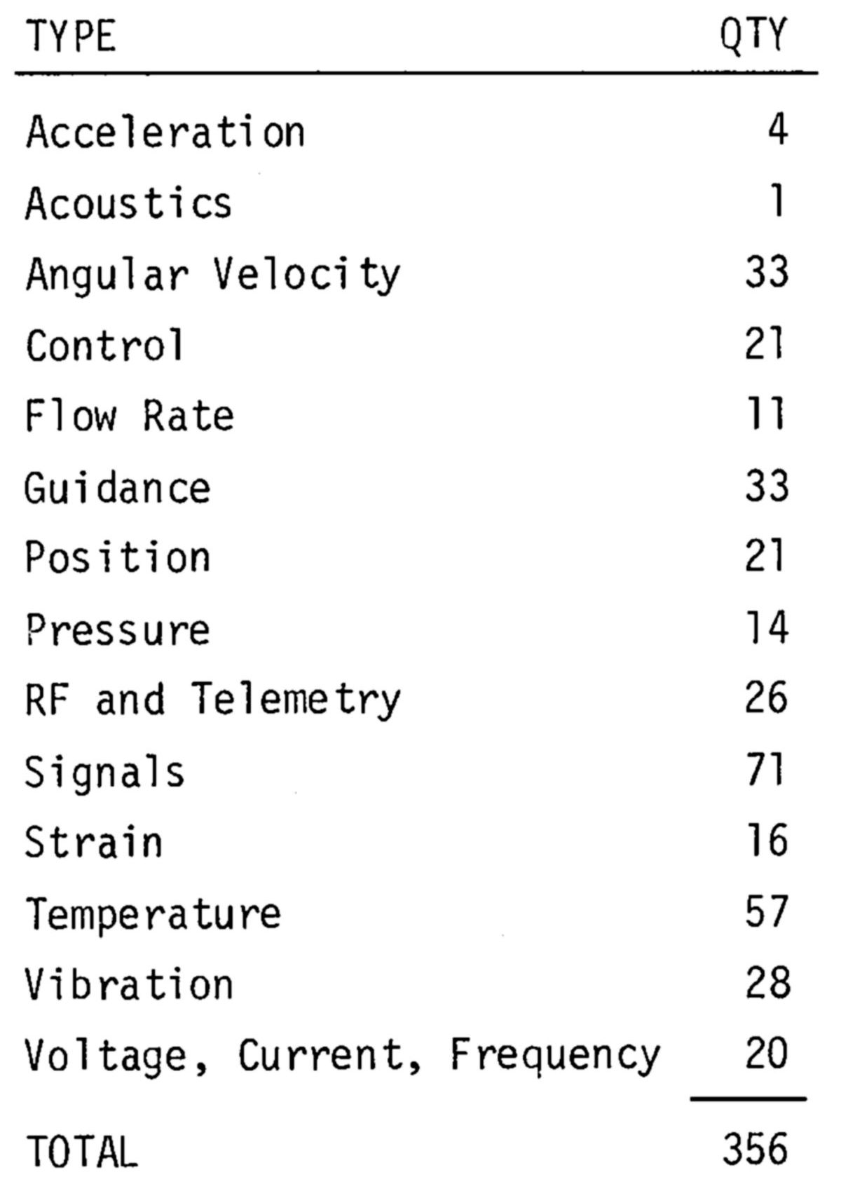
The telemetry system formatted and transmitted signals from the measuring distributor. The approximately 350 IU measurements were transmitted via four telemetry links using Pulse Code Modulation/Frequency Modulation (PCM/FM, Frequency Modulation/Frequency Modulation (FM/FM), and Single Sideband/Frequency Modulation (SS/FM). PCM/FM data were transmitted over a VHF band, a UHF band, and the CCS transponder. The SS/FM and the two FM/ FM links were transmitted over separate VHF bands.
Multiplexing — In order for the four IU telemetry links to handle in excess of 350 separate measurements, the links were shared via multiplexing, making it was possible to transmit several different signals simultaneously from one telemetry system. Both frequency sharing and time sharing multiplexing techniques were used. Some multiplexers had an integral calibration generator for inflight calibration. Upon command, the calibration generator applied a sequence of five calibration voltages to all data channels, a process requiring about 400 milliseconds.
During launch vehicle staging, retrorockets created patches of ionized gas that interfered with reliable telemetry data transmission. To preclude data loss, telemetry transmission was stopped at these times, and the data put on magnetic recording tape for transmission at a more favorable time. All of the RF assemblies were essentially the same. All use combinations of solid state and vacuum tube electronics. Frequency outputs of each unit were different and were applied to the antenna subsystem.
The antenna subsystem included equipment from the RF units' output through the radiating or receiving elements.
 |
 |
| Telemetry System | Command Communication System |
Command Communications System (CCS)
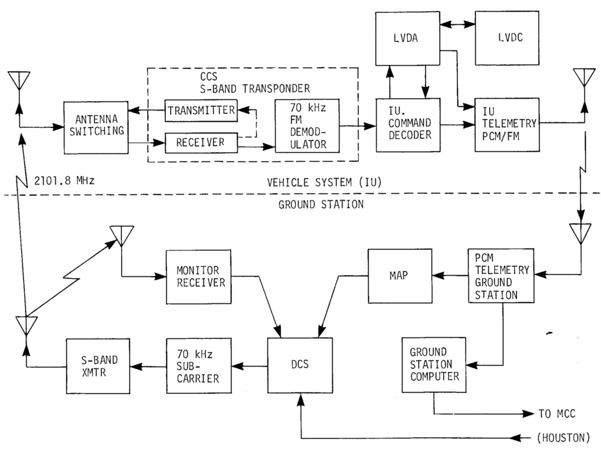
The CCS provided for digital data transmission from ground stations to the LVDC. This communications link updated guidance information, or commanded certain other functions through the LVDC. Command data originated in the Mission Control Center, and was sent to remote stations of the MSFN for transmission to the launch vehicle. At the time the spacecraft separated from the IU/S-IVB, the IU CCS transmitter was commanded off for a short period of time to preclude interference with the spacecraft S-band transponder. After adequate separation of the spacecraft and IU/S-IVB, the IU CCS transmitter was commanded on again and provided psuedo-random noise (PRN) for turnaround ranging to facilitate IU/S-IVB tracking.
The CCS equipment, located in the IU, consisted of transmitting and receiving antenna systems (directional and omni), antenna switching elements (coaxial switches, hybrid rings and power divider), an S-band transponder, and the command decoder, which precluded unauthorized command data entry. Command messages were transmitted from the unified S-band ground stations on a carrier frequency of 2101.8 MHz, modulated by a subcarrier of 70 kHz, which was modulated by a digital message. The transmitted message was received by the airborne transponder, where demodulation was accomplished. The resulting digital message was passed on to the command decoder, where it was checked for authenticity before being passed to the LVDC. The IU PCM telemetry system verified receipt of the message.
Saturn Tracking Instrumentation
Radio tracking determined the vehicle's trajectory. Tracking data was used for mission control, range safety, and post-flight vehicle performance evaluation. The Saturn V IU carried two C-band radar transponders. Launch vehicle tracking was divided into four phases: powered flight into earth orbit, orbital flight, injection into mission trajectory, and coast flight after injection. Continuous tracking was required during powered flight into earth orbit. Because of the long burn time (about 11 minutes and 17 seconds) of the three-stage launch vehicle, the end of the powered flight phase could not he covered sufficiently from land-based tracking stations. Therefore, tracking ships located in the Atlantic ocean obtained tracking data during earth orbit insertion, which was required for orbit determination. The number of stations that could see the vehicle depended on the launch azimuth. The launch vehicle was also tracked from S-band stations at Cape Canaveral and on the Atlantic tracking ships. These stations could simultaneously track the two S-band vehicle transponders, one in the IU and the other in the Apollo spacecraft. The S-band station on Bermuda had only a single capability, and tracked the Apollo spacecraft transponder. During orbital flight, tracking was accomplished by S-band stations of the MSFN and by C-band radar stations. The S-band stations, including the Deep Space Instrumentation Facility, could track the Apollo spacecraft to the moon, and was also be involved in tracking after trans-lunar injection. Tracking information collected during orbital flight was used to update Saturn guidance before mission trajectory injection.
IU Ground Support Equipment
The IU, because of its complex nature, required many types of GSE (mechanical, pneumatic, hydraulic, electrical, electronic) and personnel. There were three primary interfaces between the IU and its GSE. One was the IU access door, used during prelaunch preparations, for battery installation, ordnance servicing, IU equipment servicing , S-IVB forward dome, and LM servicing. The second interface was the umbilical, through which the IU received ground power, purging air and N2, coolant for environmental control, and hardwire links with electrical/electronic checkout equipment. The third interface was the optical window, through which the guidance system's ST-124-M3 stable platform was aligned.
IU Access Door — The IU structure consisted of three 120° aluminum honeycomb sandwich segments, joined to form a cylindrical ring. After IU assembly, a door provided access to the electronic equipment inside the structure. This access door acted as a structure load support. Work platforms, lights, and air-conditioning were used inside the IU to facilitate servicing. When the spacecraft was being fueled through the IU access door, a special protective cover was installed inside the IU to protect components from any possible volatile fuel spillage. About 20 hours before launch, the IU flight batteries, each weighing 165 pounds, were activated in the battery shop and installed in the IU through the access door. At about T-6 hours, the service equipment was removed and the access door was secured.
IU Umbilical — The physical link between the IU and GSE was through an umbilical connection located adjacent to the access door. The umbilical was made up of numerous electrical connectors, two pneudraulic couplings and an air conditioning duct. The electrical connectors provided ground power and the electrical/electronic signals necessary for IU equipment prelaunch checkout. The pneudraulic couplings circulated GSE-supplied coolant coolant for the IU/S-IVB ECS. The air conditioning duct provided compartment cooling air or purging GN2. The umbilical was retracted at liftoff, and a spring loaded door on the IU closed to cover the connectors.
Optical Alignment — The IU contained a window through which the ST-124-M3 stable platform had its alignment checked corrected by a theodolite located in a ground hut and a computer feedback loop. By means of this loop, the launch azimuth was monitored, updated and verified to a high degree of accuracy.
IU/SLA Interface Mechanical Interface
The IU and spacecraft-LM adapter (SLA) were mechanically aligned with three guide pins and brackets. The pins facilitated alignment of the close-tolerance interface bolt holes, when the two units were joined during vehicle assembly. Six bolts were installed around the circumference of the interface and sequentially torqued, using a special MSFC-designed wrench assembly. These six bolts secured the IU/SLA mechanical interface.
The IU/spacecraft electrical interface consisted of three 61-pin connectors, which provided for power, control, indication and EDS circuitry.
The IU Legacy
Nine IUs flew aboard Saturn IBs and thirteen flew aboard Saturn Vs; all were unqualified successes.
During the SA-502 (Apollo 6) mission, J-2 engine No. 2 on the S-II stage began to lose chamber pressure. The IU detected the anomaly and attempted to shut down the offending engine. Unfortunately, the cutoff signals between engines Nos. 2 and 3 were switched, so the No. 3 engine shut down. Sensing the loss of chamber pressure in No. 3, the IU attempted to shut down No. 3, an action that ultimately shut down No. 2. The IU had never been specifically programmed to handle a two-engine-out situation, but it maintained vehicle control and extended the runs of the remaining engines in order to achieve the best trajectory possible under the circumstances.
Mission SA-507 (Apollo 12) launched into an overcast with rain at 11:22 EST on 14 Nov 1969. Mission rules prohibited a launch into cumulonimbus (thunderstorm) clouds, but no lightning had been observed or reported and the launch proceeded. No one had considered that the fire and smoke from the first-stage burn left a conductive ionized trail from the launch site to the rocket. At T+36.5 seconds, lightning struck the rocket, and then again at T+52 seconds. The two lightning strikes temporarily knocked out power in the Apollo 12 CSM, but the unaffected IU continued the launch into earth orbit as programmed, where the Apollo crew restarted the CSM electrical and navigation components, and went on to a highly successful lunar landing mission.
Caveat — The IU continued to evolve as the Apollo program progressed. As each mission was different, the specific IU equipment for each mission may have differed from what is here described.
References
Astrionics Systems Handbook: Saturn Launch Vehicles, MSFC No. IV-4-4011 (Huntsville, AL: Marshall Space Flight Center, 1 Nov 1968).
Haeussermann, Walter Description and Performance of the Saturn Launch Vehicle’s Navigation, Guidance and Control System NASA TN D-5869 (Washington, DC: NASA, Jul 1970).
Saturn IB/V Instrument Unit System Description and Compinent Data, MSFC No. III-5-509-4 (MSFC, Alabama: MSFC, 1 Jun 1966).
Saturn V Flight Manual, AS-507 (Apollo 12), MSFC-MAN-507 (MSFC, Alabama: MSFC, 15 Aug 1969).
Saturn V Guidance Computer Semiannual Progress Report, 1 Apr - 30 Sep 1963, MASA-CR-155998 (MSFC, Alabama: IBM, 31-Oct 1963).
Saturn V Launch Vehicle Data Adapter Laboratory Maintenance Instructions, Vols. 1 & II, NASA-CR-124313 (MSFC, Alabama: IBM, 26 Feb 1965).
Saturn V Launch Vehicle Digital Computer Laboratory Maintenance Instructions, Vols. 1 & II, NASA-CR-124280 (MSFC, Alabama: IBM, 4 Jan 1965).
Saturn V Launch Vehicle Guidance Equations, AS-504 (Apollo 9), D5-15706-4 (MSFC, Alabama: Boeing Co., 15 Jul 1967).
Thomason, Herman E. A General Description of the ST-124-M Inertial Platform System, NASA TN D-2983 (Washington, DC: NASA, Sep 1965).
--- This concludes coverage of the Saturn V Launch Vehicle. ---
-- On to articles about the Apollo Spacecraft. ---
Send mail to
![]() with questions or comments about this web site.
with questions or comments about this web site.
![]()