U.S. Manned Rocket Propulsion Evolution
Part 5: The Atlas Missile
Compiled by Kimble D. McCutcheon
Published 1 Jan 2021; Revised 9 Jan 2025
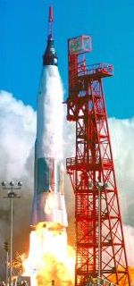
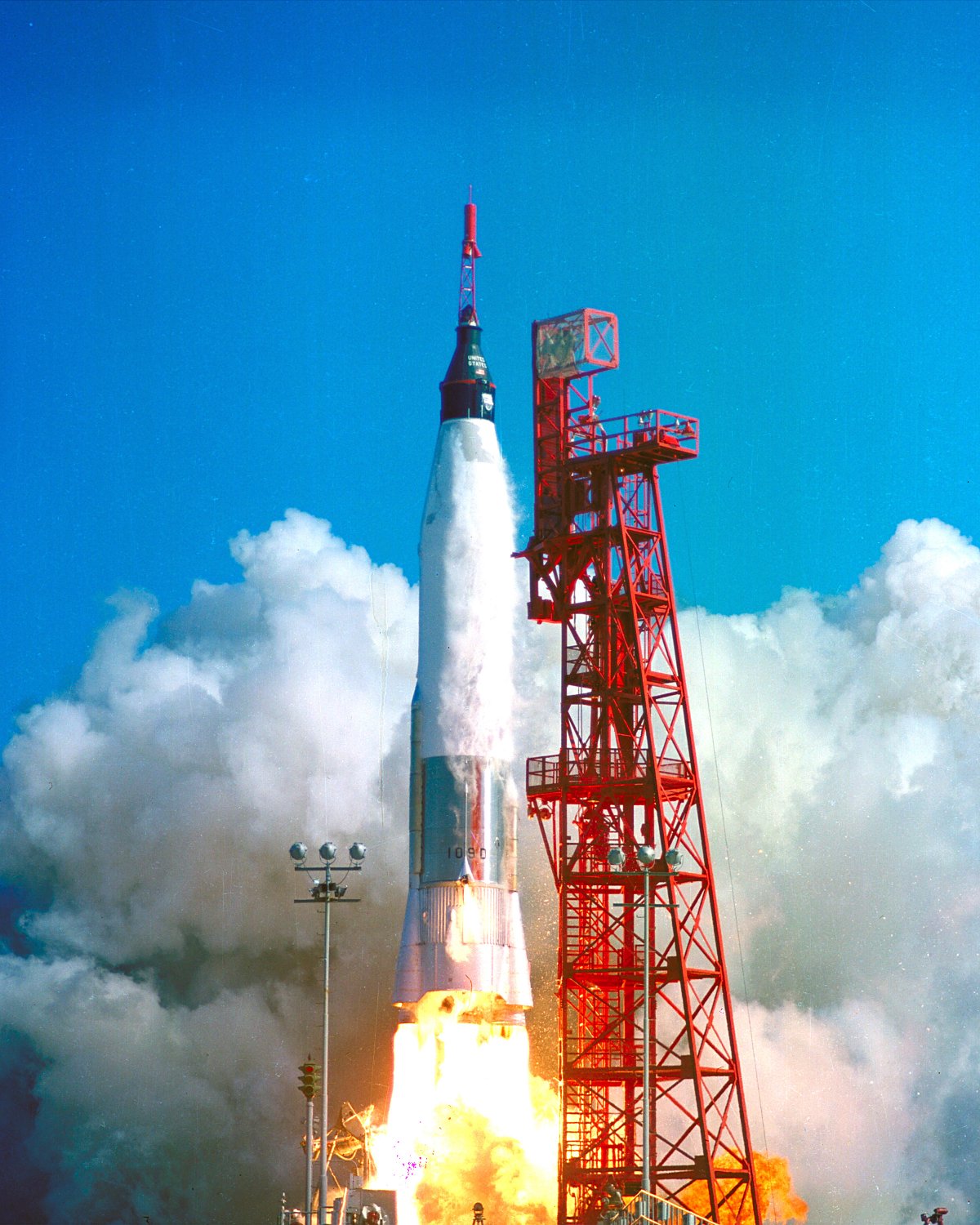
Friendship 7 (NASA) |
The Atlas program grew from the same October 1945 U.S. Army Air Forces long-range surface-to-surface missile solicitations that had resulted in the Navaho program. Led by Belgian-born Karel Bossart, Consolidated Vultee Aircraft Corporation’s (Convair) engineering team submitted a proposal on 10 Jan 1946 for a rocket-powered ballistic missile with a 6,000 mile range. This innovative design featured a thin-walled (0.020”) stainless-steel monocoque “balloon” structure kept rigid by internal pressure, gimbaled engines, a stage-and-a-half concept whereby the two large booster engines were jettisoned after about two minutes of flight, and a detachable warhead. Convair got a contract to build and test ten MX-774 Hiroc missiles, but this contract was canceled due to defense budget cuts after only three had been built. Using the remainder of the contract money, plus some Convair money, these three Hiroc missiles were launched from White Sands Proving Grounds during late 1948. Though only partially successful, these tests validated Bossart’s balloon structure and gimballed engines.
When the Korean war broke out in 1950 and defense R&D money started flowing more freely, Convair, which had been acquired by the Atlas investment group in 1947, got a new contract (MX-1593) in September 1951, to design the surface-to-surface strategic ballistic missile named Atlas (XB-65 / XSM-65) that was based on Hiroc technology. The Atlas missile that resulted could launch a 3,000-lb warhead to a target 5,500 nautical miles away with a 1,500-foot CEP. |
Atlas Overview
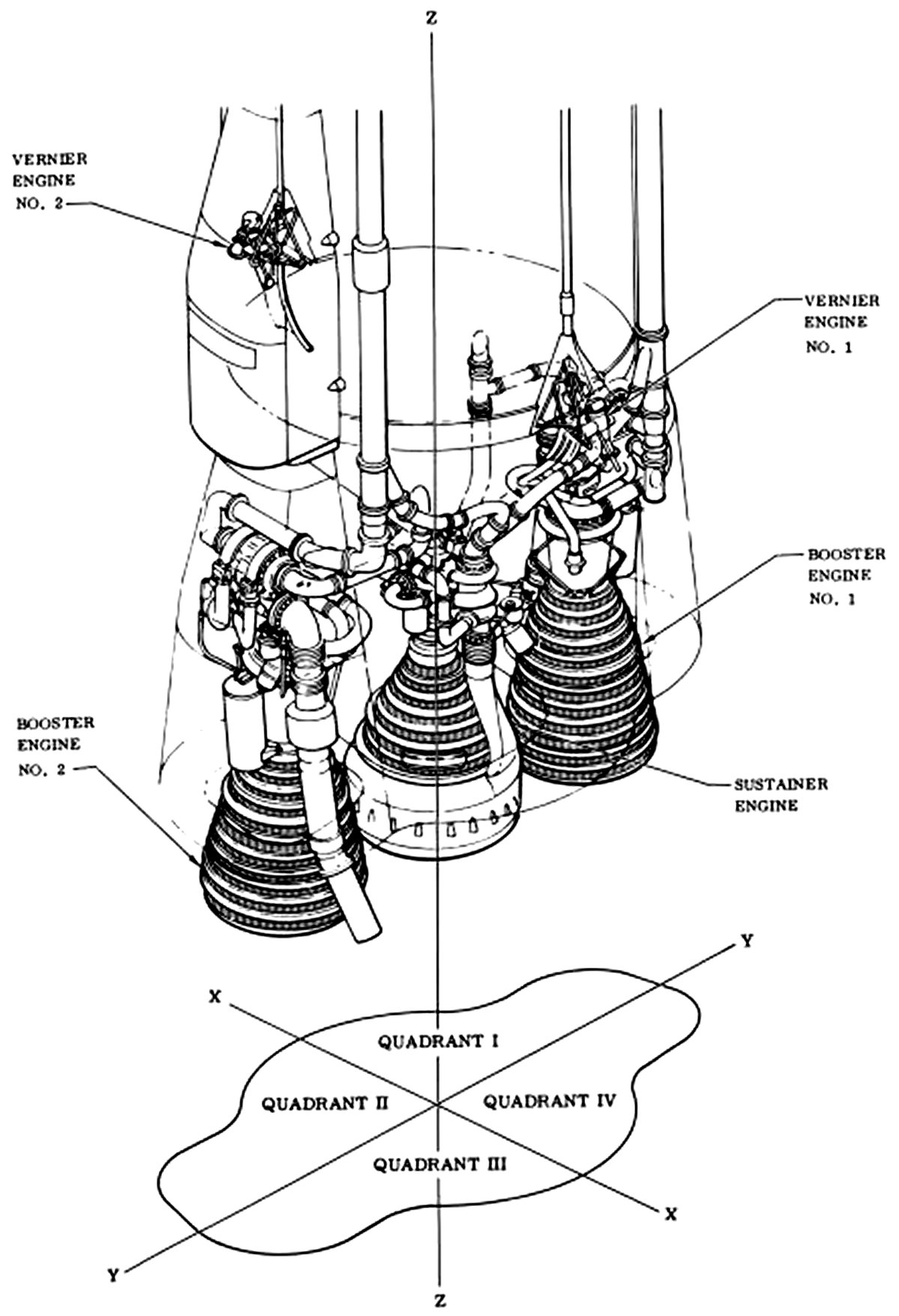
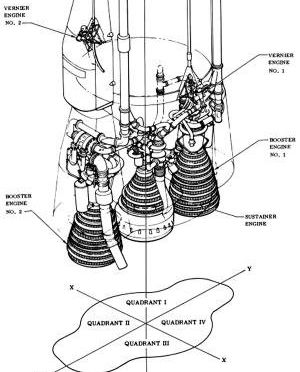
Atlas missiles used five Rocketdyne engines; two LR89 boosters, a single LR105 sustainer engine, and two LR101 vernier engines that provided roll control and fine targeting. Bossart realized that much of the risk in multi-stage liquid-fuel rockets involved starting the upper-stage engines in flight, and employed an innovative approach to mitigate this risk, which was the 1-1/2 stage booster concept. All five engines were started prior to launch. This meant that if an engine failed to start, or failed to generate full power, that all could be shut down and the launch aborted.
General Dynamics acquired the Convair Division in 1953 and realizing the value of the Atlas missile in the new cold-war environment, pushed hard for Atlas program funding. This funding arrived in January 1955 as Weapon System WS107A-1, which received the highest national priority. The Atlas ICBM program, with its missile design and production, along with the construction of 129 missile launch complexes, was an eight billion dollar program. By contrast, the Manhattan Project, which developed the first U.S. atomic bomb, cost two billion dollars and the WWII Boeing B-29 program cost three billion dollars. [http://www.astronautix.com/a/atlas.html]
 |
 |
 |
 |
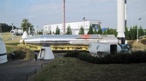
USSRC NASA Mercury-Atlas
The boat tail and outboard booster engines were jettisoned after about two minutes. The sustainer and verniers ran for the rest of the boost. (Author) |
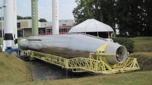
USSRC NASA Mercury-Atlas
A small air compressor can be heard to run periodically, keeping the thin balloon tanks pressurized. (Author) |
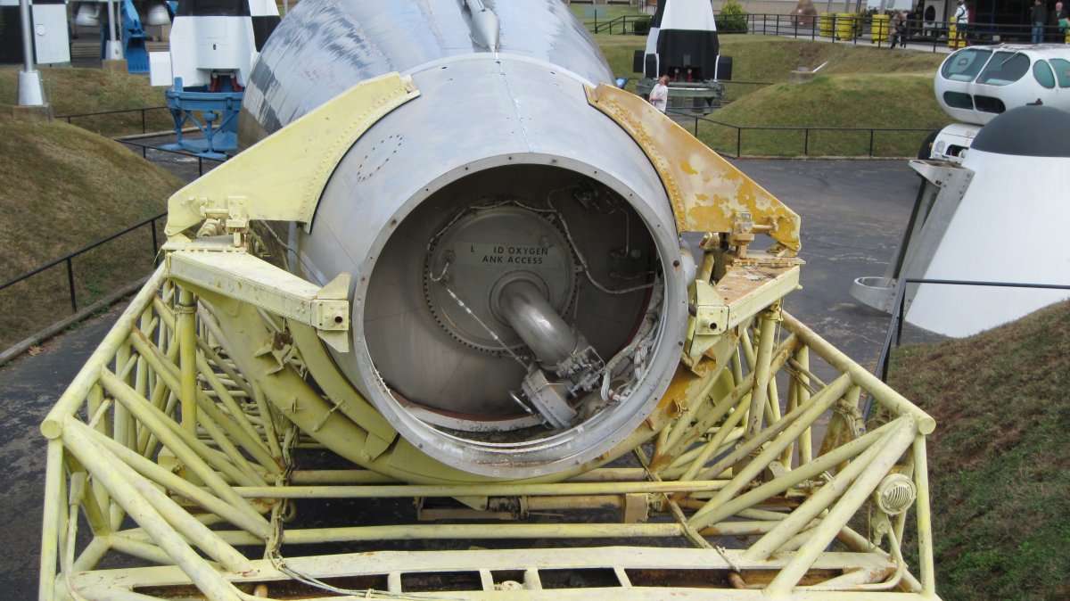
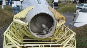
USSRC NASA Mercury-Atlas
The front end is reinforced to accommodate a spacecraft. (Author) |
USSRC NASA Mercury-Atlas
Spacecraft Mounting Flange Detail (Author) |
Atlas Testing
The innovative but complex Atlas missile system had its share of development problems and spectacular failures. Atlas’s history is instructive about the close integration between vehicle and engine, more so than with any other prime mover, except possibly scramjets. Development issues, in conjunction with ever-changing basing schemes, resulted in seven Atlas variants; originally the XB-65 experimental bomber, then SM-65A through SM-65F. New designations in 1962 reflected the basing modes. Strategic Missile (SM) became CGM-16 for what had been SM-65D and SM-65E for Containerized Guided Missiles that were stored horizontally in hardened “coffins” and erected before launch. SM-65F became SGM-65 for Silo Guided Missiles that were stored in hardened silos and lifted out by an elevator prior to launch.
Atlas A (SM-65A) was a full-scale prototype intended to test the balloon structure and booster; eight were built and launched. As such it had no sustainer engine, just the two XLR89-1 booster engines. The first four used Navaho-derivative engines that only generated 135,000 lbT. The first three missiles were used for static firings, with the fourth, No. 4A, attempting a flight on 11 Jun 1957. After 26 seconds, the B-2 engine’s LOX feed duct collapsed and the engine shut down. Shortly thereafter the B-1 engine shut down. The missile started tumbling end-over-end until the range safety officer destroyed it. The duct failure had resulted from excessive heating during a ground test, followed by more heating during the flight attempt. Convair wanted to install a better heat shield, but the Air Force objected. Atlas No. 6A was launched on 25 Sep 1957 with identical results. This time instrumentation had been installed around the engines and it became clear that excessive heat and vibration had precipitated the failure. After considerable rework of the heat shield, propellant feed ducts and engine installation, the third launch attempt was finally successful, as was the fourth flight.
At this point a predecessor to the MA-1 engine (more about these designations later) was installed along with an updated guidance system and testing resumed. After two outright failures due to guidance system failures and a third partial success due to turbopump failure, the final flight was a complete success. Of the eight Atlas A missiles launched, only four did not result in vehicle destruction. [https://en.wikipedia.org/wiki/SM-65A_Atlas, http://www.astronautix.com/a/atlasa.html]
Atlas B (SM-65B) was an Atlas prototype designed to test the complete missile system planned for the operational environment. It featured the three-engine 1-1/2 stage system with two XLR-89-5 booster engines, one XLR105-5 sustainer engine, and two XLR101 vernier engines, the combination known as MA-1. It also included a detachable nose cone, new guidance system and new tracking system. The Atlas B first flew on 19 Jul 1958. Of the ten missiles built and launched, six were successes and much was learned from the failures, which were traced to things like forgetting to power a gyroscope package, turbopump failure, premature sustainer engine cutoff, and thrust section overheating. One of the successes, and the only orbital launch, was launched on 4 Feb 1959 and placed the SCORE communication satellite into orbit, a U.S. first. [https://en.wikipedia.org/wiki/SM-65B_Atlas, http://www.astronautix.com/a/atlasb.html]
Atlas C (SM-65C) was the final development prototype. It featured a larger LOX tank and smaller fuel tank, lighter-weight components, and manufacturing productivity improvements. It continued to use the MA-1 propulsion package. It first flew on 24 Dec 1958. Of the six built and launched three were successful. The failures were traced to a guidance system fault, a staging valve malfunction, and premature booster engine shutdown. [https://en.wikipedia.org/wiki/SM-65C_Atlas, http://www.astronautix.com/a/atlasc.html]
Atlas D (SM-65D) was the first Atlas missile to be deployed. Using lessons learned from previous versions, the Atlas D included the higher-thrust Rocketdyne MA-2 propulsion system and a radio-based ground-controlled guidance system. It first flew on 14 Apr 1959. Despite how far the Atlas program had come since its inception, it was still a dangerous weapons system, which accounted for a number of failures. Launch preparation involved a fueling operation that took about 15 minutes and constraints with the radio guidance system limited the time between launches to about 5 minutes. A total of 30 were deployed at 4 locations. [https://en.wikipedia.org/wiki/SM-65D_Atlas, http://www.astronautix.com/a/atlasd.html]
Atlas E (SM-65E) was an improved version of the Atlas D. Its MA-3 booster engines each had a turbopump rather than the single turbopump for both booster engines that Atlas D had used. Atlas E also had a new inertial guidance system that did not require the radio link of Atlas D. It first flew on 11 Oct 1960. A total of 28 were deployed at 4 locations. [https://en.wikipedia.org/wiki/SM-65E_Atlas, http://www.astronautix.com/a/atlase.html]
Atlas F (SM-65F) was a quick-launch version of Atlas E. Rather than being stored horizontally in a hardened “coffin” and erected prior to launch as the Atlas Ds and Es had been, Atlas F was deployed vertically in underground silos equipped with blast doors and an elevator to raise the missile into firing position. If placed on alert status it was loaded with fuel, which could be stored for extended periods. When a launch was ordered LOX was loaded, the elevator raised and the missile launched. The Atlas F first flew on 9 Aug 1961. A total of 72 were deployed at 6 locations. [https://en.wikipedia.org/wiki/SM-65F_Atlas, http://www.astronautix.com/a/atlasf.html
 |
 |
 |
 |
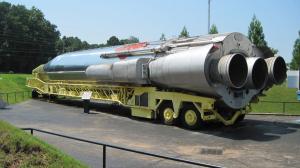
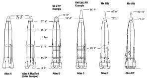
| The Atlas ICBM Family (Convair) |
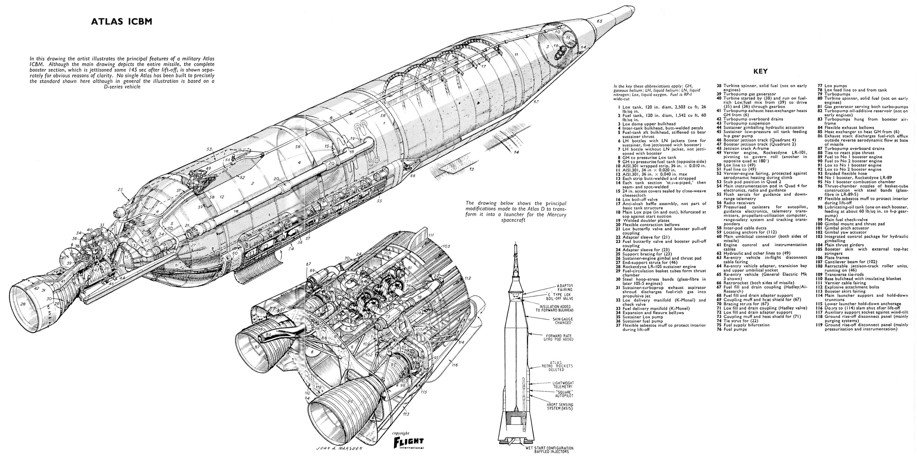
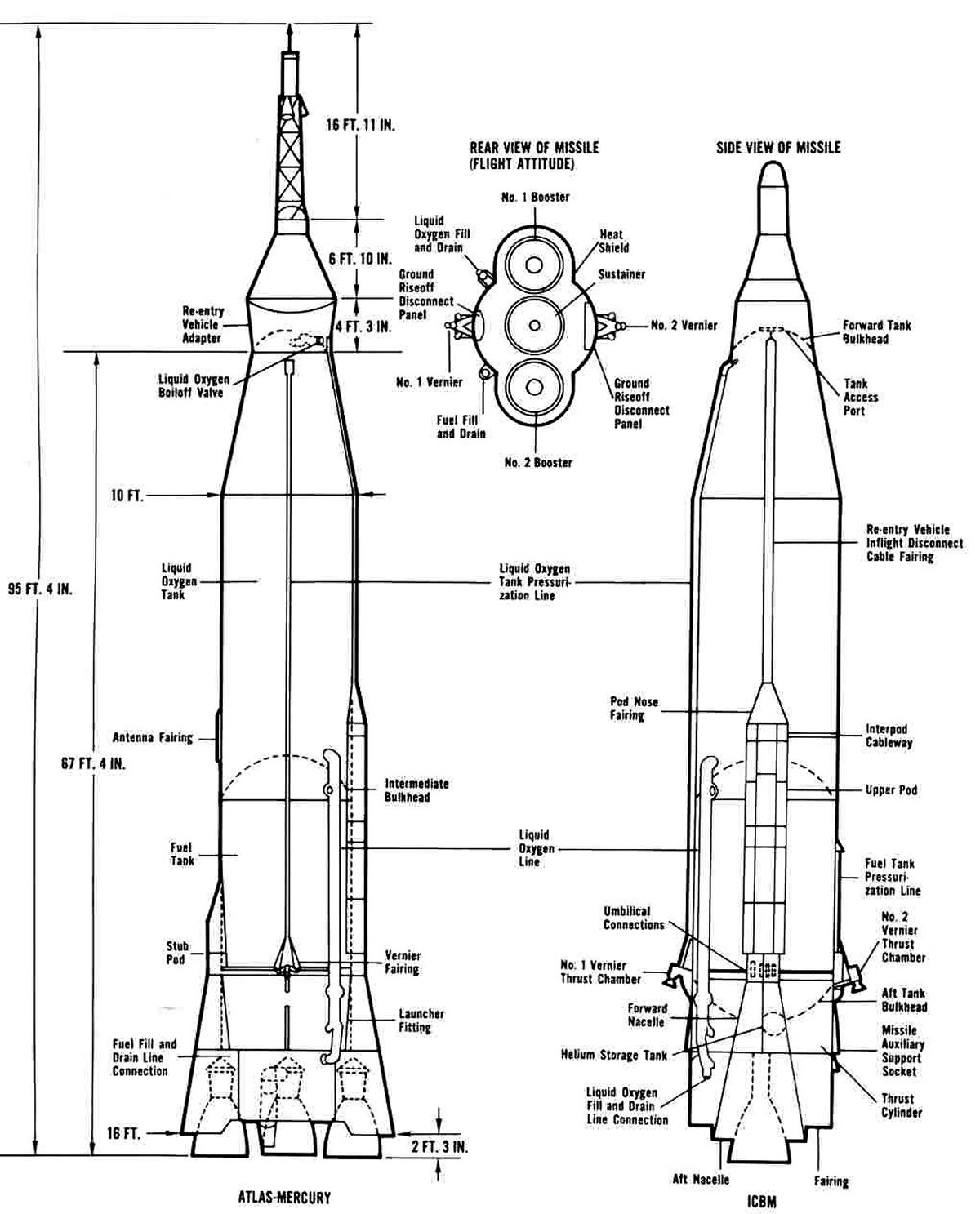
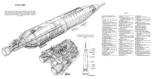
Atlas Cutaway (Flight International) |
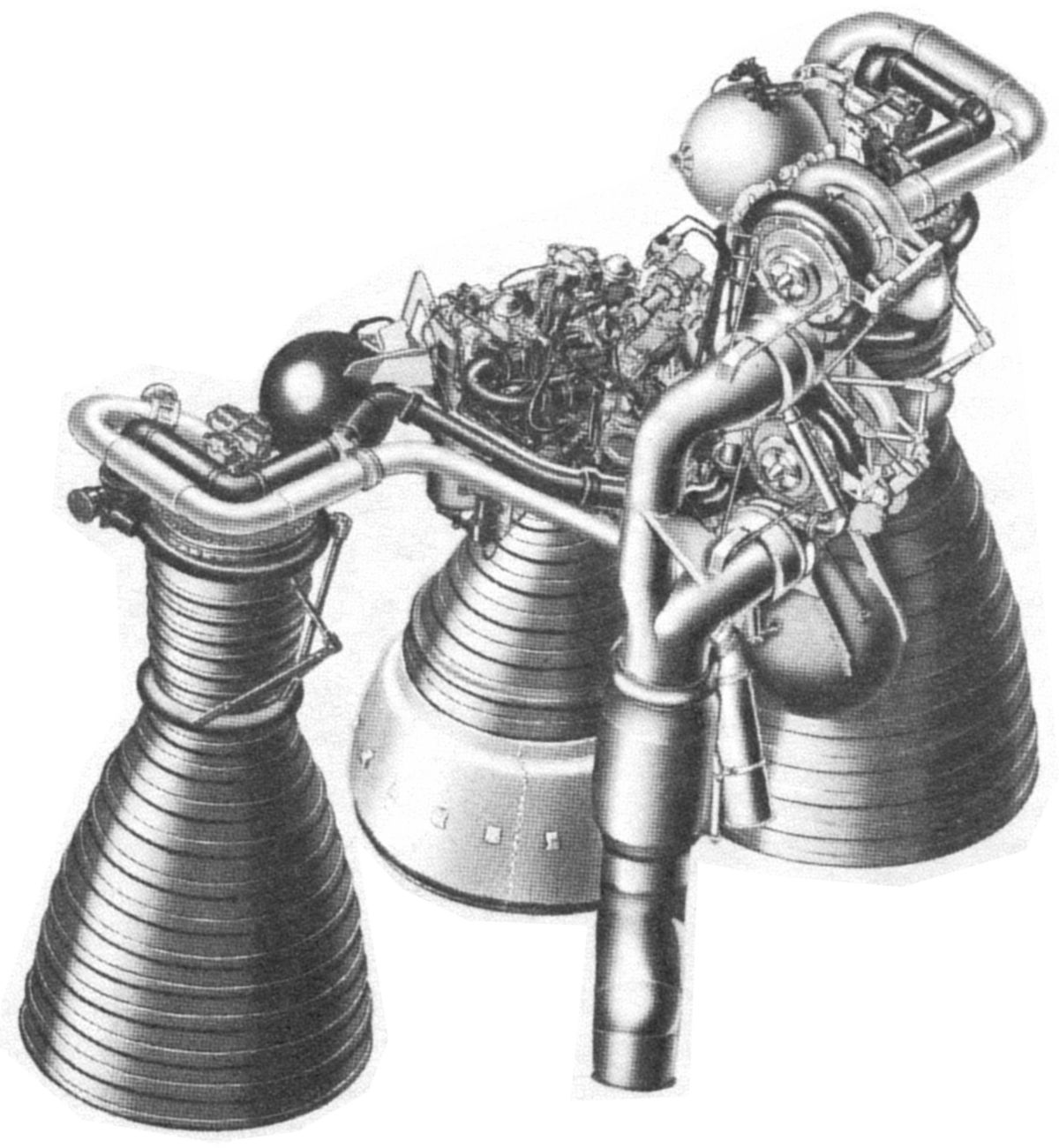
Atlas Propulsion (Convair) |
Mercuary-Atlas Comparison (NASA) |
Retired Convair/General Dynamics Titan IV Centaur Chief Engineer Allen Vinzant relates an interesting story about the Atlas cutaway published by Flight International and reproduced above. In the mid-1950s, the U.S. Government encouraged British rocket development as a deterant to possible U.S.S.R attacks against its European allies. Rocketdyne and General Dynamics were directed to share data with British representatives. This data was ultimately used to help develop the de Havilland Propellers Blue Streak intermediate range ballistic missile and its Rolls-Royce RZ.2 engine. Vinzant recalls that British engineers were permanently stationed at Convair’s San Diego plant, had access to technical data and freedom to attend design reviews and meetings. While they were NOT allowed to copy drawings, they could sketch all they wanted and take copious notes. Vinzant believes this data was used to generate the Flight International drawing.
Atlas ICBM Family Characteristics
| |
Atlas A |
Atlas A Mod |
Atlas B |
Atlas C |
Atlas D |
Atlas E/F |
| Gross Lift Off Weight (lb) |
180,666 |
200,834 |
248,006 |
242,493 |
264,235 |
265,474 |
| Approximate Booster Weight at Burnout (lb) |
N/A |
N/A |
8,800 |
7,084 |
7,040 |
7,810 |
| Approximate Sustainer Weight at Burnout (lb) |
17,721 |
17,659 |
8,734 |
7,920 |
7,700 |
7,304 |
| Payload Weight (lb) |
154 |
3,494 |
3,494 |
2,794 |
2,420 |
3,797 |
| Propulsion |
XLR89-1 |
XLR89-1 |
MA-1 |
MA-1 |
MA-2 |
MA-3 |
| Liftoff Thrust (lbT) |
271,432 |
301,369 |
356,655 |
356,655 |
365,992 |
386,192 |
| Sustainer Thrust (lbT) |
N/A |
N/A |
55,882 |
55,882 |
58,876 |
58,876 |
| Booster Isp SL / Vac (sec) |
245 / 282 |
245 / 282 |
245 / 285 |
245 / 285 |
248 / 287 |
253.5 / 290.0 |
| Sustainer Isp SL / Vac (sec) |
N/A |
N/A |
210 / 302 |
210 / 302 |
213 / 305 |
215.5 / 308.9 |
Service
The first Atlas launch complex became operational on 2 Sep 1950. The solid-propellant Minuteman missile, introduced in 1963, made the Atlas obsolete, and all launch complexes were closed by 1966. About 350 Atlas missiles were built. At the end of their service life many Atlas D, E and F missiles were stored, refurbished, and used as space launch vehicles. New Atlas versions with Agena and Centaur upper stages and different engines continue to be built and launched. [https://en.wikipedia.org/wiki/SM-65F_Atlas, http://www.astronautix.com/a/atlas.html]
The Birth of WD-40
The Atlas skin, welded together from thin type 301 stainless steel sheets, was prone to corrosion and cracking in portions of the welds’ heat-affected zones; this corrosion was especially troublesome in the salt atmosphere near an ocean. Convair contracted with the Rocket Chemical Company of San Diego, California to develop a coating that would displace water and protect the skin. It took 40 attempts to get the formulation correct, hence Water-Displacing formula 40, or WD-40.
Mercury-Atlas (LV-3B)
When planning to orbit the first U.S. astronaut, NASA had the choice of one acceptable launch vehicle Atlas D. Trouble was, only about 50% of the early Atlas tests were successful. Mercury astronauts witnessed the second Atlas D test on 18 May 1959; it exploded after 62 seconds. This was the fifth straight Atlas failure. Gus Grissom wondered, "Are we really going to get on top of one of those things?"
Convair opened a separate assembly line for Mercury-Atlas (also known as LV-3B) rockets. The new line was staffed with hand-picked personnel who were indoctrinated on the importance of the U.S. manned space program and the importance of their work in making it successful. MA-2 propulsion systems in the middle of the MA-2 performance spectrum were selected in hope they would be more reliable than the performance outliers. Convair and NASA established such rigid quality assurance standards that LV-3B vehicles took twice as long to manufacture and three times as long to test and verify for flight.
NASA also ordered a number of changes to the stock Atlas D design. These included the following:
- Engine alignment was altered to eliminate a tendency for some engines to induce a rolling moment.
- A plastic liner was added to the LOX pump to prevent impeller blade rub possibly causing a spark.
- The guidance program was changed to eliminate features not required for launch to orbit.
- Thicker skin was used to support the added weight and flight loads of the Mercury capsule and launch escape system.
- The propellant utilization system was modified to ensure the LOX supply was completely exhausted prior to sustainer engine cutoff.
- Foam insulation was removed from the bulkhead separating the LOX and fuel tanks.
- Redundant electrical circuits were installed to ensure that propellant valves would open in the proper sequence during engine start, and that sustainer engine cutoff would occur as commanded.
- Engine combustion instability resulted in the loss of six Atlas Ds. Three of these losses resulted from rough starts that were addressed with combustion sensors that shut down rough-running engines before they could explode. In addition, the engine cooling tubes were filled with an inert liquid that smoothed the starts. Another problem resulted from high-frequency resonance where burning propellant would swirl around the injector, destroying the engine with shock waves. This was fixed by installing baffles on the injector face that broke up the resonance.
- Atlas C LOX boil-off valves were substituted for the standard Atlas D part because they were thought to be more reliable and were lighter.
- More modern transistorized autopilot assemblies from Atlas E and F were used instead of the stock electromechanical Atlas D units.
- The range safety system was modified for Mercury-Atlas to include a three-second delay between engine cutoff and vehicle destruction. This gave the launch escape system time to pull the Mercury capsule away from the failing missile.
- A rate gyro package was added to sense some guidance and control system failure modes.
- An Abort Sensing and Implementation System (ASIS) was developed to detect malfunctions and trigger launch aborts. Malfunctions detected by the ASIS included booster trajectory deviation, low engine thrust, low hydraulic pressure, low propellant tank pressurization, booster electrical system failure and ASIS failure.
Mercury-Atlas Program
A total of 10 Mercury-Atlas rockets were built and launched. Five of these were unmanned tests, one carried a chimpanzee, and the last four were orbital missions with U.S. astronauts aboard. Only three of the test flights could be called successful and even they had their share of glitches.
On 21 Feb 1962, astronaut John H. Glenn, Jr. “...got [sic] on top of one of those things..” in a Mercury spacecraft named Friendship 7 and orbited the earth three times, becoming the first U.S. astronaut to do so. Astronaut M. Scott Carpenter repeated this feat in Aurora 7 on 24 May 1962, with three orbits. On 3 Oct 1962 Walter M. Schirra, Jr. achieved six orbits in Sigma 7, setting a record for the longest time in space. The final Mercury-Atlas flight launched on 15 May 1963 with L. Gordon Cooper in Faith 7. Cooper completed 22 orbits. [https://en.wikipedia.org/wiki/Atlas_LV-3B
Atlas Propulsion
Rocketdyne designed engines for the U.S. Army Jupiter, and U.S. Air Force Thor and Atlas missiles almost simultaneously, and the three engine designs had much in common. Rocketdyne introduced five key innovations when developing the Navaho Phase II and III propulsion systems, which led to Jupiter/Thor propulsion.
- RP-1 and LOX were chosen as the fuel and oxidizer.
- Gas generators replaced the steam generators for turbopump power.
- Thrust chambers were formed from thin-walled tubes brazed together.
- Bell-shaped nozzles replaced the conical ones of the V-2 and Redstone.
- Rocket directional control was achieved through the use of gimbaled engines.
RP-1 Fuel. When burned, ethanol produces 11,600 BTU/lb, while JP-4 jet fuel produces about 18,500 BTU/lb. In its direction of the Navaho program, Wright Field insisted that it be fueled by JP-4, which was intended to give it more power per pound. Rocketdyne objected, because JP-4 production and purity standards were too loose to permit its use as a rocket fuel. Finally, a highly-refined version of JP-4 known as RP-1 (Rocket Propellant 1) was developed. RP-1 refining removing most of the long-chain hydrocarbons that were solidifying and clogging rocket engine cooling tubes, and drastically reduced the amount of sulfur to prevent tube cracking. LOX was retained as the oxidizer. This propellant combination became the basis for a number of rocket engines. [Hunley, 122]
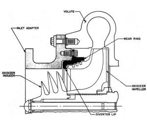
Gas Generators. Steam-driven turbopumps, which had been used on the V-2 and Redstone, in addition to having power limitations, were heavy and complicated. Navaho Phase II introduced turbopump gas generators fueled by the same propellants used in the rocket engine combustion chambers. The new MK-3 turbopump turbine drove high-pressure fuel and oxidizer pumps through a high-speed gear train, which reduced the turbine size and weight while increasing its efficiency.The turbopump was started by a solid-propellant gas generator that spun the turbine long enough to build up the pressure required to operate the liquid-propellant gas generator. The new turbopump design suffered some development failures. The turbine was much smaller than those used in V-2 and Redstone engines and rotated at a much faster 30,000 rpm. The gearbox reduced this to about 6,500 rpm for the RP-1 and LOX pumps. Several gearbox failure modes were identified. Its lubrication system was redesigned, the gear case strengthened and a roller bearing redesigned. Turbine blades, which had cracked because of vibration and flutter, were given a tapered profile and interlocking tip shrouds, all of which changed the blade natural frequency and restricted its movement. Sustainer engine LOX pump impeller rubbing was solved by changing the pump clearances and installing plastic liners. Once the problems were sorted out the turbopumps became reliable. [Hunley, 123]
 |
 |
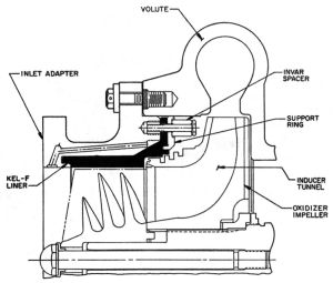 |
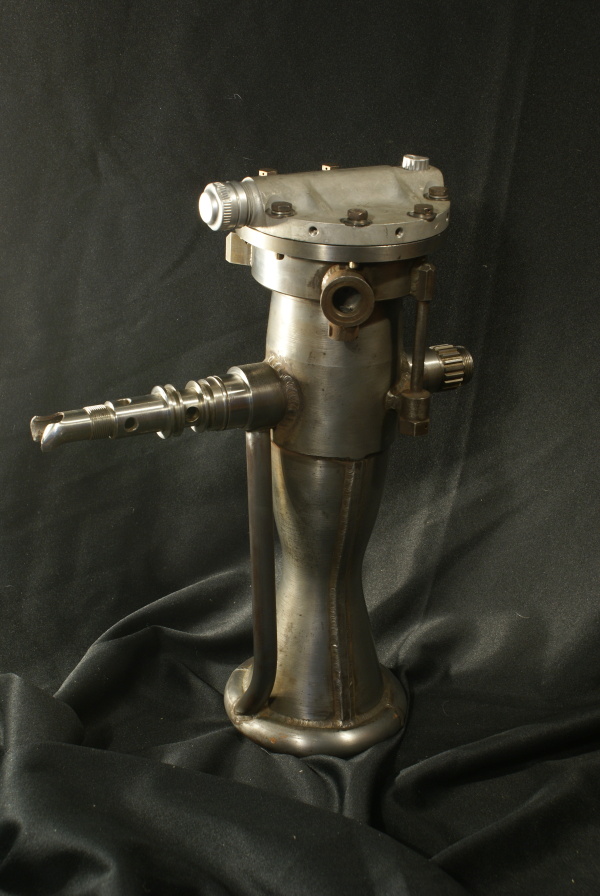
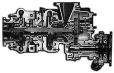
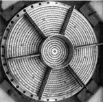
| LR105 Turbopump. LOX pump is on the left, fuel pump is in the center and turbine is on the right. (Rocketdyne) |
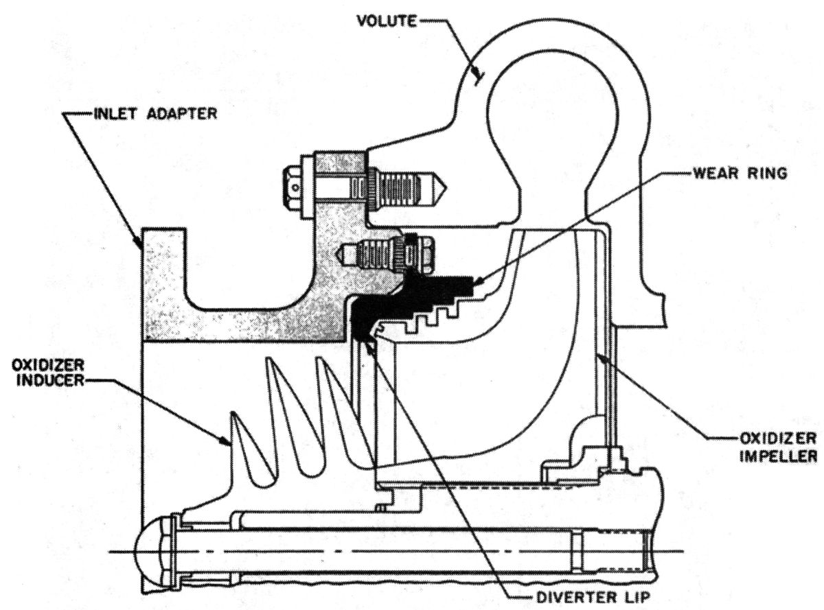
LR105 LOX Pump Original Configuration
(Rocketdyne) |
LR105 LOX Pump with Plastic Liner
(Rocketdyne) |
Baffled LR89 Injector
(Rocketdyne) |
Thrust Chambers. Double-walled regeneratively-cooled thrust chambers, used in the V-2 and Redstone, had been pioneered in the 1930s by James H. Wyld of the American Rocket Society, and later, Reaction Motors/Thiokol. Unfortunately, these formed and welded sheet metal thrust chambers were difficult and expensive to fabricate, were heavy and, with their thick inner walls, did not cool very well. Edward A. Neu, Jr. of Reaction Motors invented another approach that used pre-formed tubes that were brazed together to form thrust chambers. Fuel flowed from the injector through some of these tubes to a manifold at the nozzle exit, where it reversed direction and flowed back to the injector, where it was injected and burned. Circumferential bands strengthened the assembly, and this construction was adopted for nearly all liquid fuel rocket engines (see US Patent 3,190,070).
The flat injector faces used in booster and sustainer engines occasionally suffered high-frequency combustion instability that could alter the heat transfer characteristics and destroy an engine (and rocket) in less than a hundredth of a second. Baffles were attached to the injector fact that served to prevent this high-frequency vibration from ever becoming resonant. [Hunley, 124]
Bell-Shaped Nozzles. Conical nozzles used on the V-2 and Redstone did not produce an ideal axial exit gas flow pattern. By the mid 1950s, computers had become available that allowed Rocketdyne's G.V.R. Rao to calculate ideal nozzle shapes and dimensions, which form the now-familiar bell shape. [Kraemer, 83]
Directional Control. Both the V-2 and Redstone had used a combination of aerodynamic fins with movable tabs and carbon vanes in the exhaust stream to guide the missile. This approach had significant disadvantages, including the aerodynamic drag of the fins and vanes, along with reliability issues with the carbon vanes. Rocketdyne achieved the same result by hinging (later gimballing) engines, which used the thrust vector to control the rocket. [Kraemer, 96] This “improvement”, however, was not without its problems. Thrust vector control required much more rapid control system response than had the older carbon vanes and aerodynamic tabs.
Rocketdyne's Atlas Engine Designations
While the U.S. Air Force had its own set of engine designations (LR89, LR105, LR101), Rocketdyne designated its Atlas engine assemblies MA-1 through MA-5A. The MA-5 and MA-5A were used for space launch vehicles built after the Mercury-Atlas and the Atlas F. MA-4 was a study for a possible Titan I application that was never developed. [http://www.astronautix.com/m/index.html]
MA-1, produced in 1957 and 1958, consisted of two XLR89-1 booster engines, an LR105-3 sustainer, and two LR101 vernier engines. The two booster engines shared a turbopump and gas generator. The verniers received propellants from the sustainer. This configuration was used on Atlas B and C test missiles.
MA-2, produced from 1958 through 1962, consisted of two XLR89-5 booster engines, an LR105-5 sustainer, and two LR101 vernier engines. The two booster engines each had its own turbopump but shared a gas generator. The verniers received propellants from the sustainer. This configuration was used on Atlas D and Mercury-Atlas missiles.
MA-3, produced from 1961 through 1966, consisted of two LR89-5 booster engines, an LR105-5 sustainer, and two LR101 vernier engines. The two interchangeable booster engines each had its own turbopump and gas generator. The verniers received propellants from the sustainer. This configuration was used on Atlas E and F missiles. In addition to the interchangeable booster engines, the MA-3 also introduced a new means of initiating combustion. Previous versions had used pyrotechnic igniters to start combustion in all thrust chambers. MA-3 LR89-5 and LR105-5 engines started booster, sustainer and vernier engines by injecting a slug of hypergolic starting fluid that spontaneously combusted when it came in contact with oxygen. A mix of triethylboron and triethylaluminum, both of which are pyrophoric, was typically used. Once the gas generators started , rising fuel pressure ruptured a diaphragm in the hypergolic cartridge, releasing its contents into the combustion chamber. This meant that the MA-3 now had only one electrical line to start it and another to stop it. Unfortunately the inert liquid used to fill the thrust chamber cooling passages had to be changed from its original water-based formulation to substance that did not react with the hypergol.
MA-5, produced from 1961 through 1973, was derived from the MA-2 configuration and consisted of two LR89-5 booster engines, an LR105-5 sustainer, and two LR101 vernier engines. The two booster engines each had its own turbopump but shared a gas generator. The verniers received propellants from the sustainer. This configuration was used on Atlas launch vehicles.
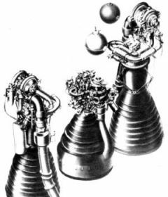
Rocketdyne's Atlas Engine Configurations
 |
 |
 |
 |
 |
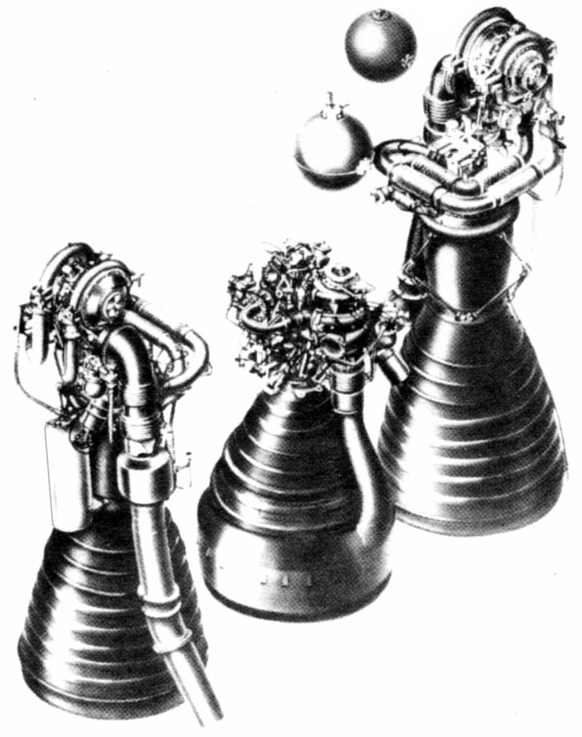
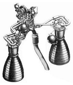
| Atlas A (Rocketdyne) |
MA-2 (Rocketdyne) |
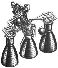
MA-3 (Rocketdyne) |
MA-5 (Rocketdyne) |
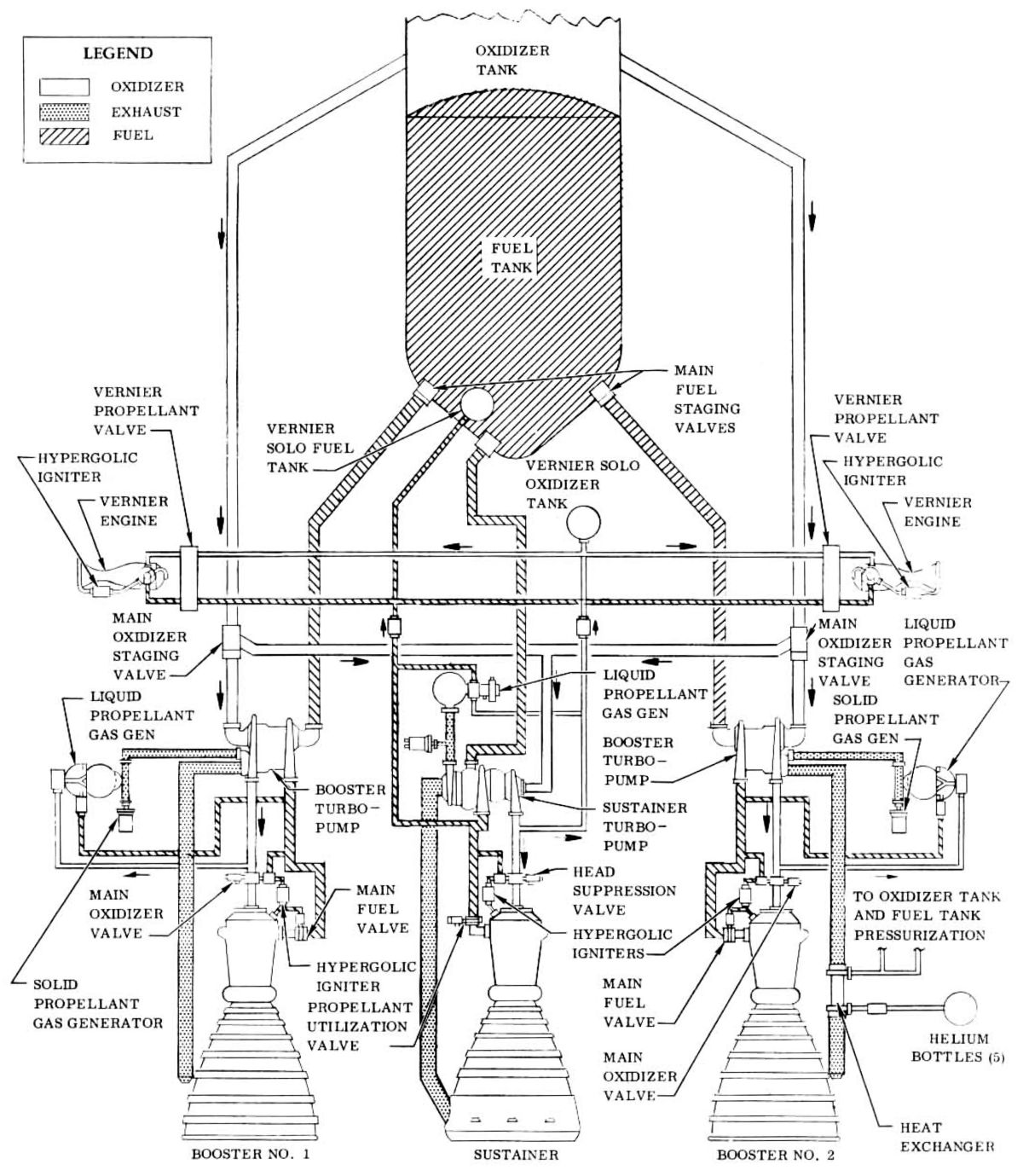
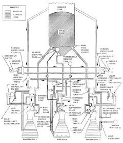
Atlas E/F Schematic (Rocketdyne) |
Two LR89 booster engines, which burned RP-1 and LOX, provided booster thrust for the Atlas launch system. They were jettisoned along with their attendant structure and plumbing after about two minutes at which time the vehicle weight had been considerably reduced due to propellant consumption.
The LR105 sustainer engine, which burned RP-1 and LOX, provided thrust from launch and after the booster engines had been jettisoned. Its fuel system also fed the vernier engines.
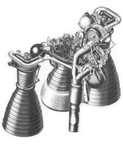
 |
 |
 |
 |
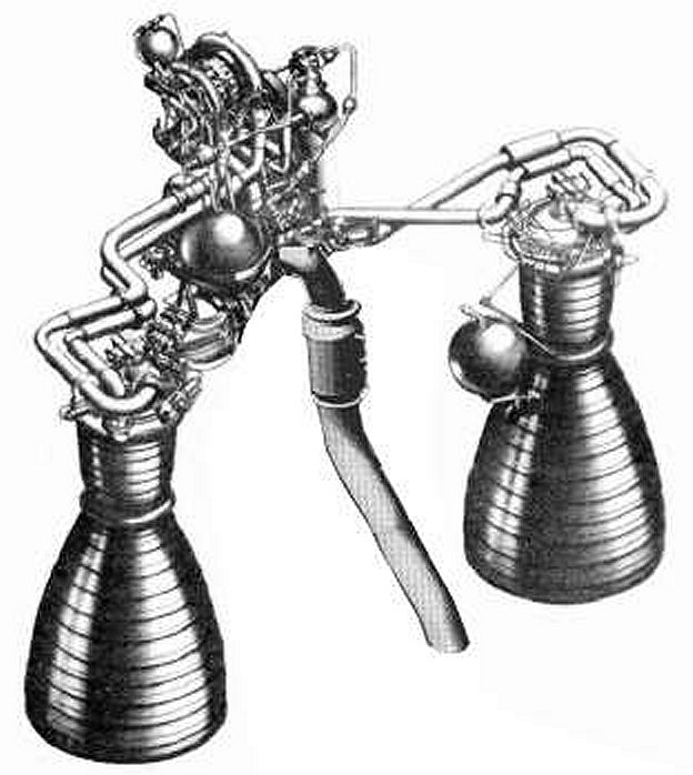
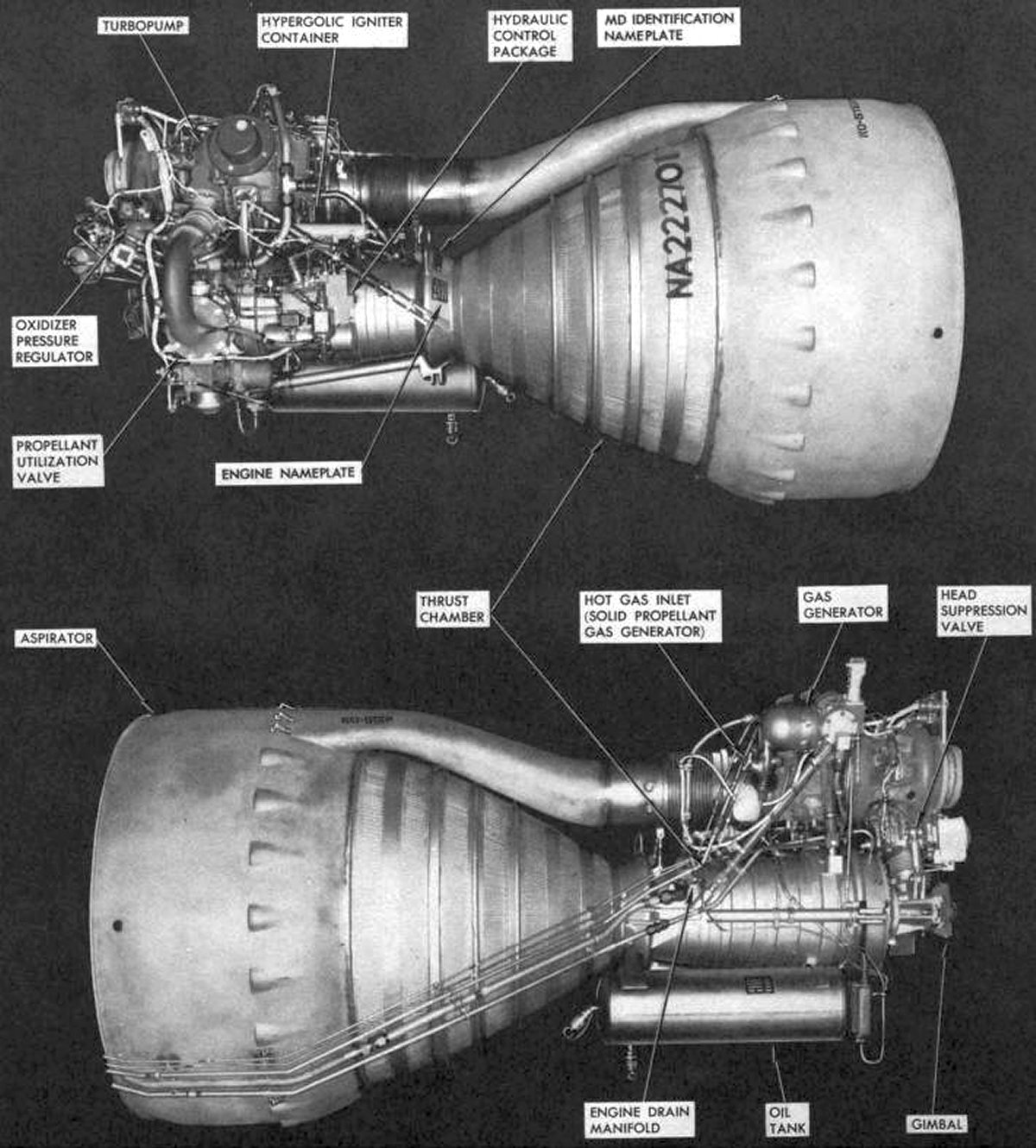
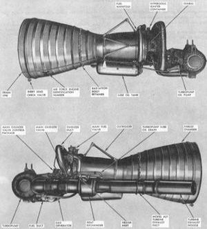
| Later Generation LR-89 Booster Engines (Rocketdyne) |
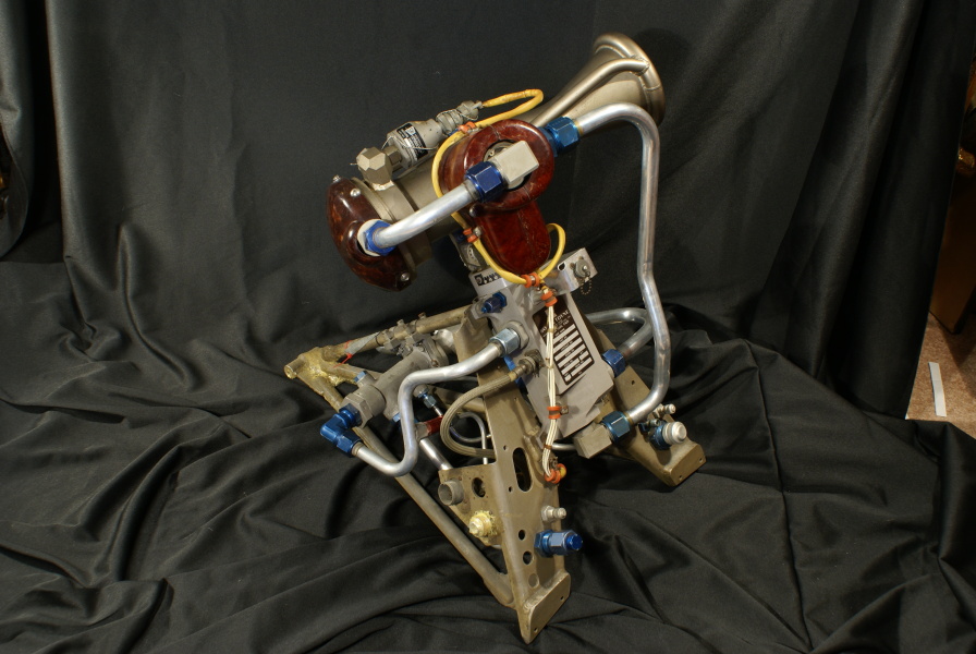
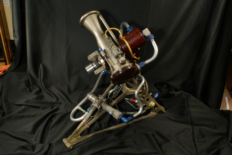
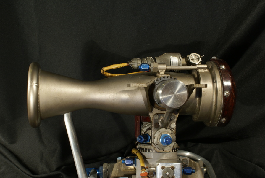
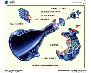
LR-105 Sustainer Engine. Note that the turbopump turbine exhausts into an aerator (also called an exhausterator)around the nozzle, improving efficiency and eliminating any rolling moments that might occur with a simple overboard dump. (Rocketdyne) |
LR-105 Sustainer Engine Details
(heriocrelics.org) |
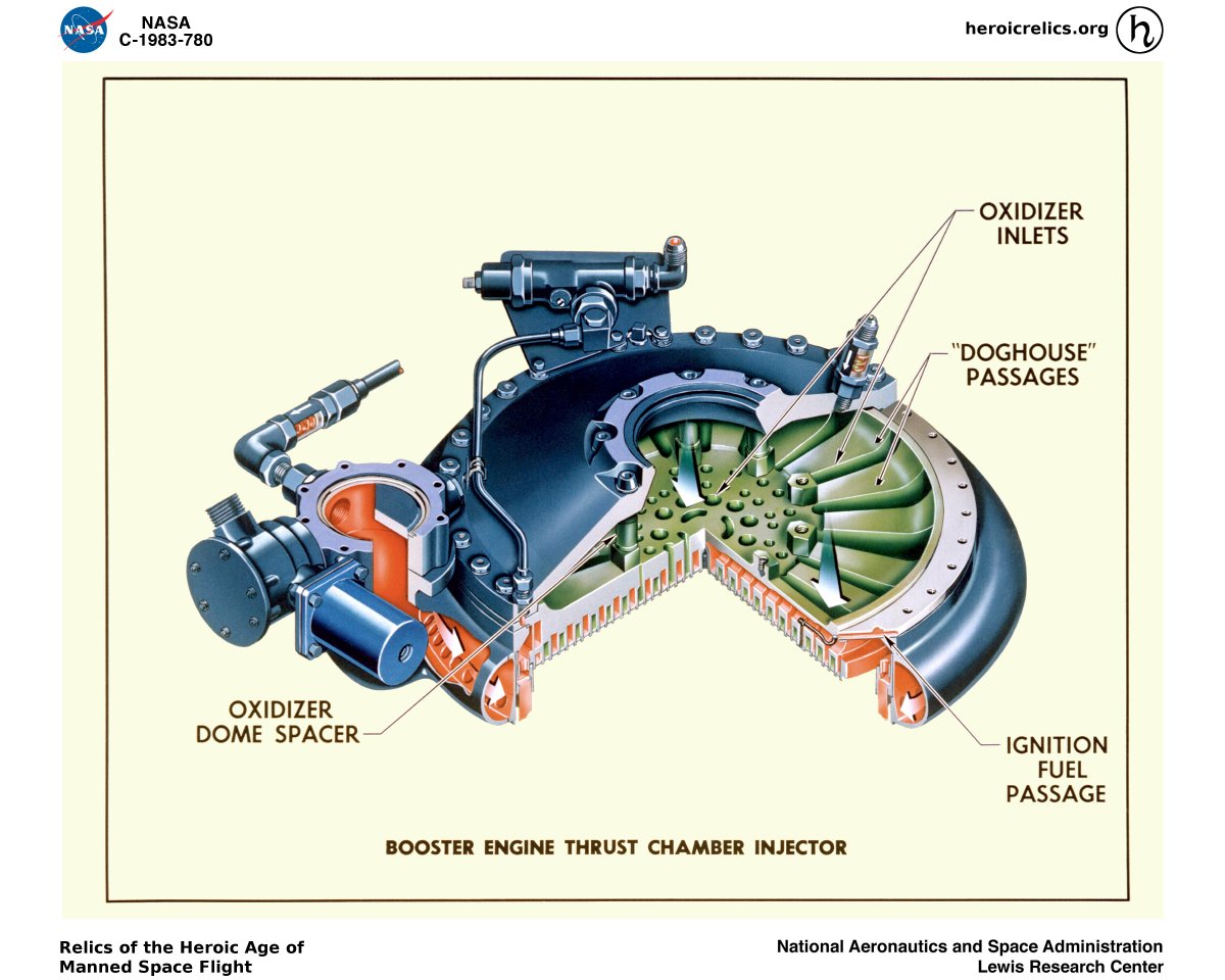
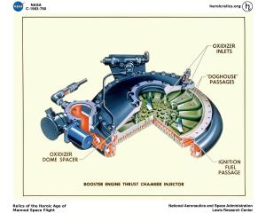
LR-89 Injector Details
(heriocrelics.org) |
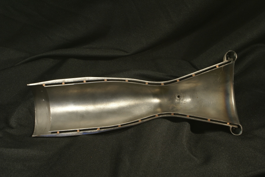
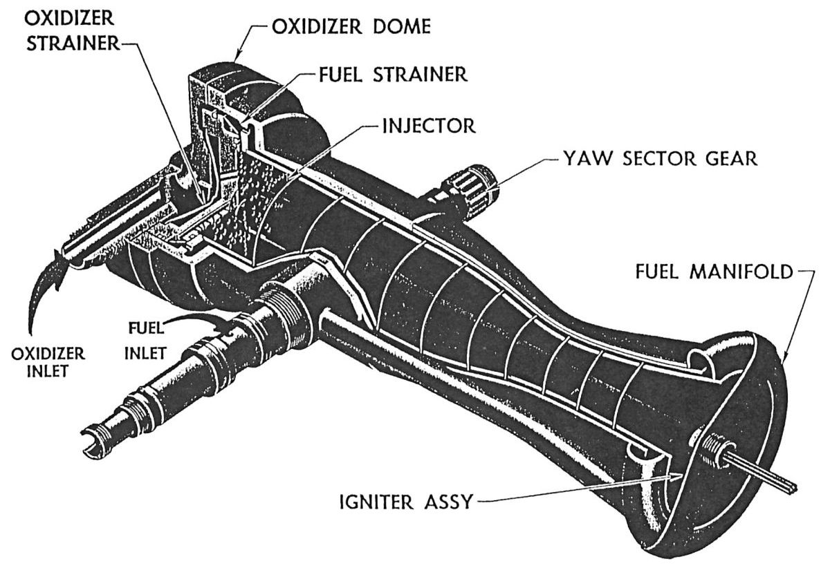
Two LR101 vernier engines provided pitch and roll control for the Atlas and Mercury-Atlas. The were fed propellant from the sustainer engine turbopump; each produced about 1,000 lbT for as long as the sustainer engine operated. The gimbaled thrust chamber was was attached to the missile via a welded tubular engine mount. Each assembly weighed 54 lb. The LR101 thrust chamber was a double-walled steel structure with spiraled captured between the walls. RP-1 fuel entered near the nozzle exit and spiraled around the nozzle and thrust chamber inner liner on its way to the injector, thereby achieving regenerative cooling. A pneumatically operated propellant valve with a valve position-indicating switch admitted RP-1 and LOX to the engine where a single-use electrically-fired pyrotechnic igniter assembly set the propellants alight. Later LR101s used a pressure-operated hypergolic igniter. Thrust chamber gimballing was achieved via a pitch gimbal shaft that moved the thrust chamber through a pitch-roll correct arc of 70° on either side of the neutral position; and a yaw gimbal shaft which permits movement of the vernier thrust chamber through a yaw correction arc of 30 degrees (outboard) and 20° (inboard) of the neutral position. In addition to performing the thrust direction gimbal function, the yaw shaft served as a manifold for passage of fuel and oxidizer to the thrust chamber.
Launch Vehicle Engine Specifications
| Engine | Model 39 | Rocketdyne
75-110-A-7 | Rocketdyne
LR89-5 | Rocketdyne
LR105-5 |
| Used In | German V-2 | Redstone | Atlas E, F | Atlas E, F |
| Era | 1943 | 1953 | 1960 | 1960 |
| Thrust, SL (lb) | 55,000 | 82,977 | 163,211 | 60,473 |
| Thrust, Vac (lb) | ? | 93,565 | 184,905 | 86,866 |
| Burn Time (sec) | 60 | 155 | 135 | 430 |
| Chamber Pressure (psi) | 218 – 239 | 318 | 580 | 696 |
| Specific Impulse (sec) | 203 – 239 | 235 – 265 | 248 – 282 | 220 –316 |
| Propellant Flow (gps) | 33.5 | 41.3 | 47.7 | 20 |
| Propellant Flow (lb/sec) | 286 | 355 | 458 | 193.2 |
| Nozzle Expansion Ratio | 2.83 | 3.61 | 8 | 25 |
| Engine Weight (lb) | 2,484 | 1,479 | 1,580 | 1,010 |
| Thrust / Weight, SL | 22 | 56 | 103 | 60 |
| Fuel | 75% Ethanol | 75% Ethanol | RP-1 | RP-1 |
| Oxidizer | LOX | LOX | LOX | LOX |
| Mixture Ratio (Ox/Fuel) | 1.13 | 1.324 | 2.21 | 2.25 |
| Turbopump Output (hp) | 580 | 758 | 3,140 | 1,663 |
| Turbine RPM | 3,800 | 4,718 | 30,986 | 30,000 |
References
Hunley, J.D. Technology for U.S. Space-Launch Vehicles, 1926 ‑ 1991 (College Station, Texas: Texas A&M University Press, 2007)
Kraemer, Robert S. Rocketdyne: Powering Humans into Space (Reston, Virginia: AIAA, 2006)
--- On To Part 6 ---