Early U.S. Navy Afterburner Development Efforts Part 4a: Westinghouse – Background and the Initial Effort – The J34-WE-11 by Paul J. Christiansen Published 7 Sep 2026
Part 4c: Westinghouse Aviation Gas Turbine Division (in process)
Part 4d: Westinghouse Aviation Gas Turbine Division (in process)
Westinghouse Electric Company, Essington, Pennsylvania
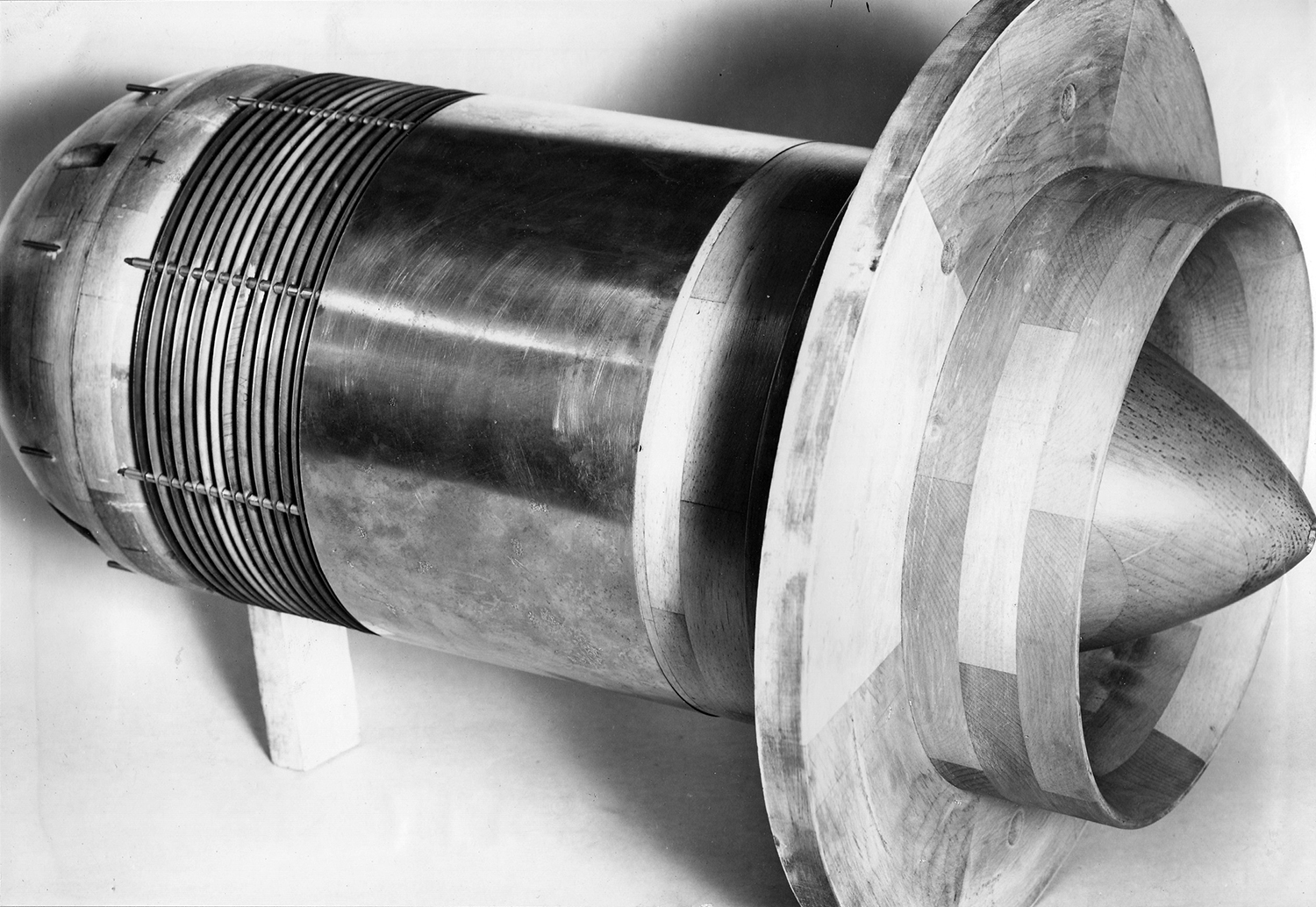
The early work by Westinghouse on the axial turbojet models 19A, 19B and its successor the 19XB-2B never included any discussion of adding reheat, tail-pipe burning or afterburning (AB) as it is known now. The early engines’ low thrusts and the performance of the McDonnell FD-1 with its J30 engines showed both the limitations of low thrust and reduced range because of high fuel consumption, but also the promise of higher speeds when more thrust became available. The idling thrust of the J30 in the FD-1 added to the difficulty in slowing the aircraft down for carrier landings and a mockup of a thrust diverter for the J30 was built but never constructed or tested. [Early Westinghouse Axial Turbojets 19A, 19B, 19XB-2B (J30), 9.5A/B (J32) Page 227, by the author.]
Fig.1. 19XB-2B Thrust Diverter Design Mockup. WAGT P33013, 5/3/1944. Courtesy of the Hagley Museum and Library.
6 March 1944: The U. S. Navy Bureau of Aeronautics (BuAer) issued a requirement to Westinghouse for an engine of 3,000 lb of thrust and a lower specific fuel consumption than the earlier models. This would emerge as the J34 in the Westinghouse (WAGT) response of April 20, 1944 as the model 23C. The “23” indicated the diameter of the engine in inches. The specification was for a booster engine and did not provide for AB support in any form. The overall design was unambitious and carried over a pressure ratio of 4:1 from the early designs. It would use a ten-stage axial compressor, two stage turbine, ball and roller bearings with engine lubrication using oil mist (similar to the very small J32) and achieve a specific fuel consumption (SFC) of 1.07 lb/hr/lb. Air flow would be 54.5 lb/sec at 12,000 rpm. Early design changes included enlarging the diameter of the combustion chamber to 24"; the WAGT model then becoming the 24C from that point forward. The engine’s prolonged development would add complexity to the various airframe manufacturers’ efforts to bring airframes to production status. The many delays and design changes to the development J34 engines also complicated the parallel efforts of Ryan, Solar and McDonnell to develop ABs that were intended to be able to be attached to the back of production J34 engines. Those airframe development histories were related in the earlier segments of this series on early Navy AB development. [The full J34 development story can be found in the author’s Westinghouse J34 Axial Turbojet Family, Development History and Technical Profiles.)
1 August, 1945: WAGT responded to a request from BuAer under Contract NOa(s) 3962 with proposal AGT-6 specifying adjustable nozzles for the 19XB and X24C-4. It included development to be complete and three fully tested variable nozzles for each model to be delivered by 1 April 1946. Development would continue with the view to making the nozzles fully automatic.
12 September 1945: BuAer rejected the 1 August proposal for the reasons of it failing to deliver a fully automatic nozzle along with production and testing of four complete nozzles (for each model) prior to delivery. They stated that manually controlled nozzles were OK until the automatic control was added later. The testing acceptance should include designs for full service usage and the passing of any qualification test and operating schedule to which the engine might be subjected.
April 1946: BuAer asked WAGT for a tail-pipe burning system proposal for the X24C engines. The variable exhaust nozzle should be integrated with this proposal as the AB would require such a nozzle anyway.
10 June 1946: WAGT’s AB proposal (AGTD-25) for a cost plus fixed price of $476,632.00 would deliver four ABs plus various design reports. The design would include the variable nozzle. The AB would attach to the exhaust extension flange of the X24C-4B without alteration and use a special type of automatic variable area exhaust nozzle operated from a single lever pilot control. Delivery would be two ABs in 18 months and two more 19 months after contract acceptance. The acceptance test would be by the Bureau Air Resident Representative (BARR) in Essington; the test run would consist of an X24C‑4B engine without alternation and the AB operation not to exceed fifteen minutes in total duration but sufficient to the demonstrate to the BARR that the guarantees were met.
BuAer failed to accept the proposal at that time. WAGT continued to develop the X24C-4B without an AB to get it through an acceptance test.
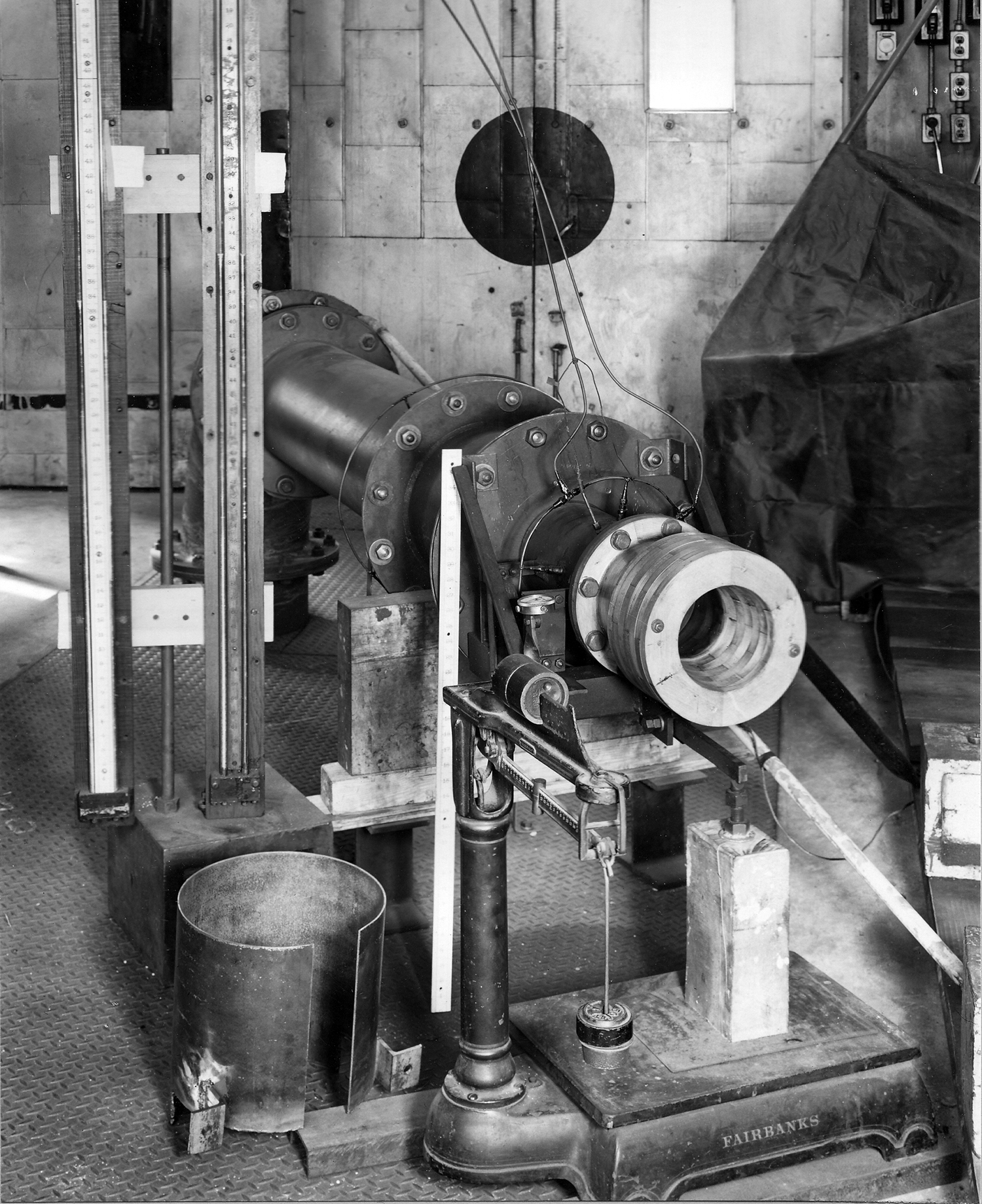
Pre-production engine design changes: During early development many changes had been made, the greatest being the addition of another compressor stage to the X24C-2 and changing the lubrication system in the middle of the development pre-production run of the model 24C‑4. This divided the run into -4A and -4B engines, the latter having “solid” oil lubrication in place of the earlier oil mist design. The -4B engine led to the first production engine model, a design produced as the J34‑WE‑22 engine. Initial production started in Essington, Pennsylvania while a new factory was outfitted and staff trained in Kansas City, Missouri to produce the very large numbers of the J34 engines that were expected to be needed by both the U.S. Navy and the U.S Air Force. The J34‑WE-22 still did not have any design elements in it to support an AB even though Ryan and Solar’s work had shown changes to the aft flange of the exhaust nozzle would need to be made to make it stronger to enable ABs to be attached. The production engine also did not have any circuits and controls for an AB as part of the engine control. A thrust diverter design was built for the 24C-4 model engines and tested. No details other than the picture (Fig. 2) were found.
Fig. 2. 24C-4 Thrust Diverter Mounted in Test Cell. WAGT P35997, 11/8/1946. Courtesy of the Hagley Museum and Library.
31 January 1947: In dialog with BuAer about the planned use of the 24C-4B production version engine in the Lockheed XP-90, WAGT stated they had no contract for AB development. They had done some work on design, construction, and very preliminary functional testing of a conservative test stand model that was not suitable for flight, but at that point all work on AB development had stopped. The test AB had a maximum burner temperature of 3,000°F and was expected to produce a thrust augmentation of 40-45% under sea-level conditions. Further development was expected to increase the burner temperature and static augmentation percentage.
A brief description of the development AB included:
A. Fuel System – solid fuel operating at about 100 psi.
B. Fuel Pump – installed on a pad of the gear box operating independently of the engine fuel system.
C. Exhaust Nozzle – fully adjustable for all altitudes and airspeeds. To be developed to be fully automatic and actuated from the engine control lever.
D. Planned investigation - Injection of fuel in front of the turbine, thus integrating the AB as part of the engine itself. A more compact burner arrangement might be possible.
Fig. 3. First WAGT Experimental AB in a Test Cell. WAGT P39116, 14 June 1948. Courtesy of the Hagley Museum and Library.
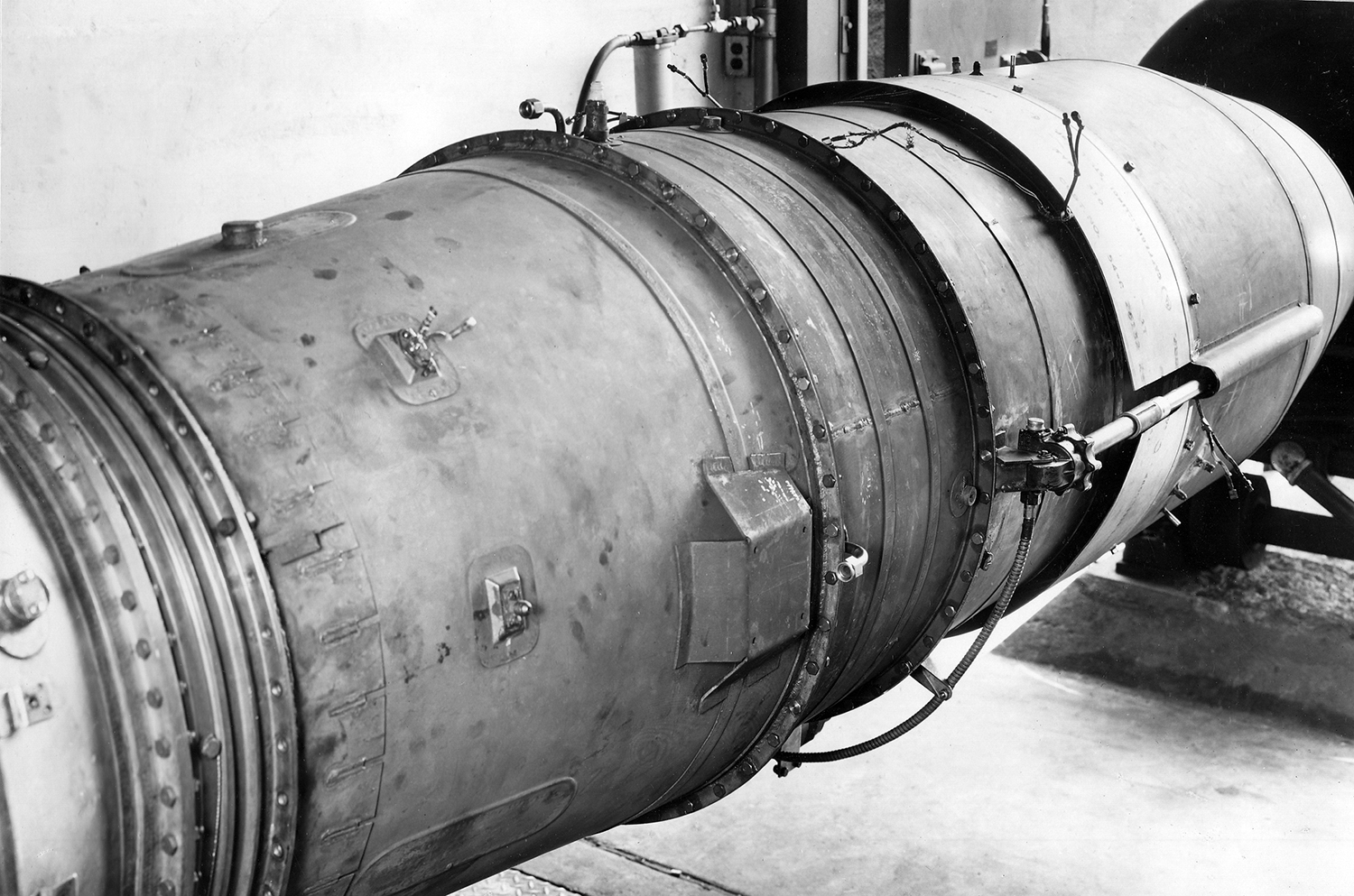
Fig. 4. First WAGT Experimental AB Side View. WAGT P39117, 14 June 1948. Courtesy of the Hagley Museum and Library.
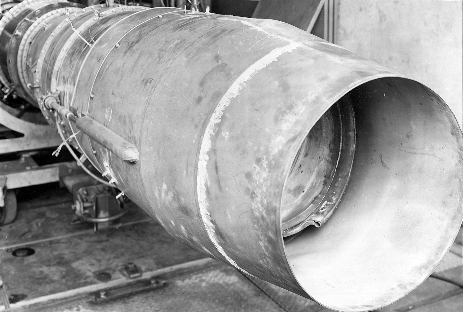
Fig. 5. X24C-4B with the First WAGT Experimental AB, Nozzle in the Fully Open Position. WAGT P39118, 14 June 1948. Courtesy of the Hagley Museum and Library.
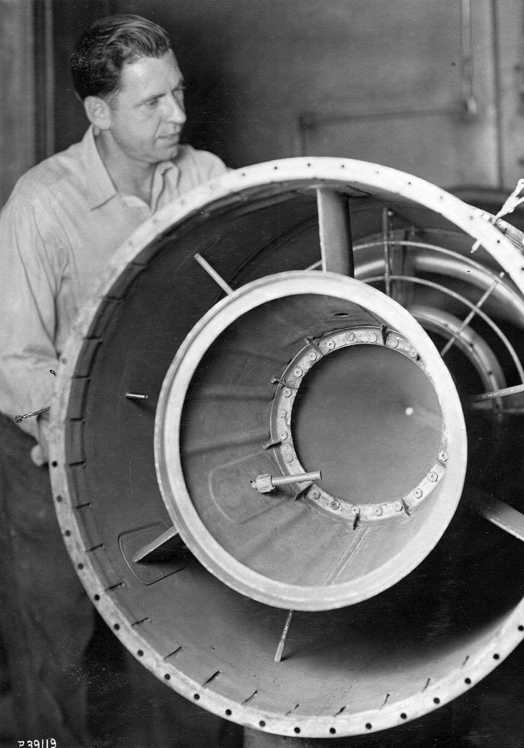
Fig. 6. First WAGT Experimental AB, Diffuser Entry Leading Back to the Combustion Chamber. Fuel Rings and Flame Holders are Visible. WAGT P39119, 14 June 1948. Courtesy of the Hagley Museum and Library.
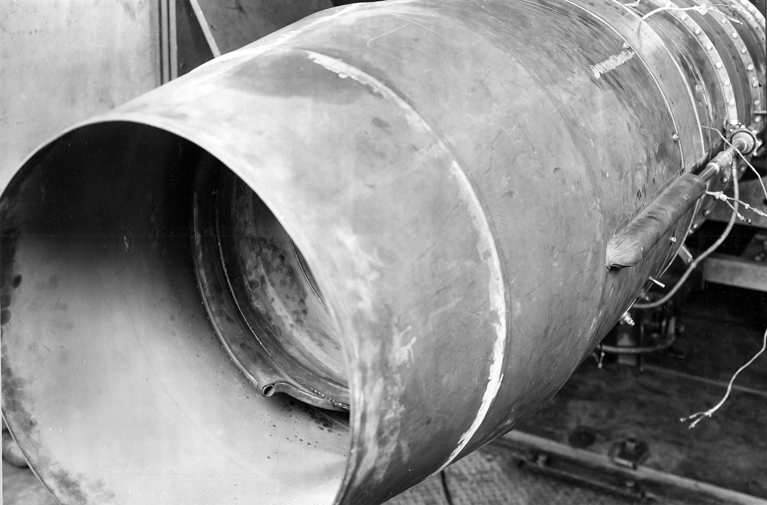
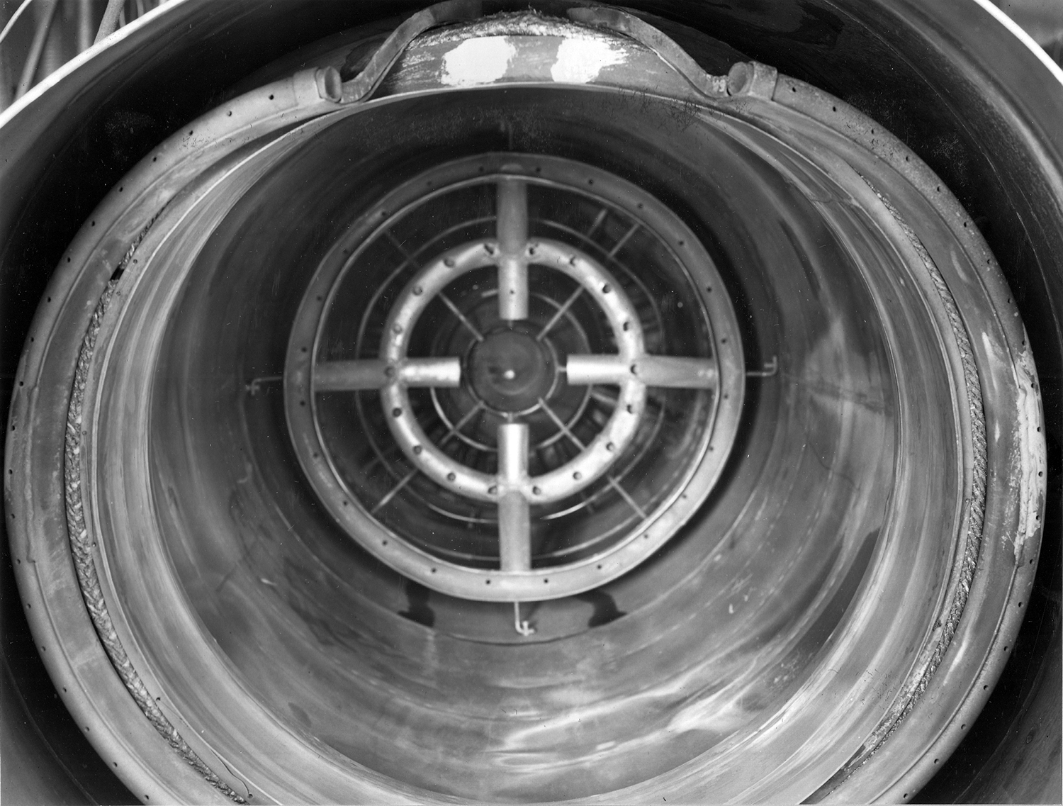
Fig. 7. First WAGT Experimental AB, Aft End Looking Forward, Eyelid Nozzle Fully Open. WAGT P39294, 15 July 1948. Courtesy of the Hagley Museum and Library.
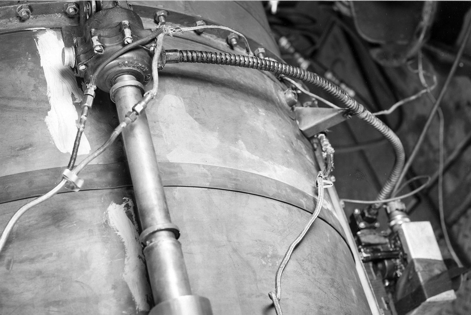
Fig. 8. Experimental AB Eyelid Drive System, View from Above. WAGT P39295, 15 July 1948. Courtesy of the Hagley Museum and Library.
15 October 1947: Another WAGT proposal for an AB development was sent to BuAer (AGT-34 – not found).
8 December 1947: BuAer responded to the proposal, saying they understood that the J34-WE-22 would need modifications to operate with an AB. These would include an automatic integrated control and might include structural revision of the turbine housing and rear flange of the basic engine to enable AB attachment. Such modifications should not affect installation interchangeability with any engines already produced. BuAer asked if WAGT could proceed with full scale engine and component testing under contract NOa(s) 5382 (J34-WE-22 production) under Section “B”, “Supporting Services”. Production could not be affected in any way and no money or time in addition to those authorized under Contract NOa(s) 5382 could be expended.
All available data from Solar, Ryan and McDonnell AB development programs would be provided to WAGT. If acceptable to WAGT as described, the BARR was authorized to approve test projects in accordance with a program agreed upon between BuAer and WAGT.
19 January 1948: WAGT notified BuAer that production J34-WE-22 engines beginning with Serial No. WE020121 would have a 0.125" combustion chamber housing rear flange. All engines with prior serial numbers should be allocated to non-AB projects.
29 March 1948: WAGT accepted the program with the limits as defined by BuAer and sent a list of the engine modifications planned to accommodate an AB:
A. Controls – The engine governor would be modified under another contract (not specified) for rapid response rate and the control lever motion modified to conform to afterburner fuel system requirements.
B. Fuel System – Only a manual fuel system would be possible with additional pilot levers and would need to be completed before funding on NOa(s) 5382 expired. Work on a more automatic fuel system would proceed to the extent possible. An engine driven afterburner fuel system would be used initially but work would be directed toward eventual use of an air driven fuel pump.
C. Ignition System – Development would be toward an ignition system that would permit ignition of the afterburner at full (Military) engine rpm under both sea level and altitude conditions. Altitude testing would be done on a combustion chamber model setup with consideration given to any scale effect(s). Engine testing would cover the sea level condition.
D. Mechanical Engine Reliability – The plan was to develop a flexible joint with suitable quick disconnect joints between the AB and engine sufficient to protect the engine from AB force and deflections.
E. Afterburner – Initial development would be aimed at a reasonably short, minimum weight AB with minimum pressure drop. Later, development would be aimed at an AB that could be incorporated more easily in various airplanes. It was anticipated this AB would be slightly heavier.
F. Exhaust Nozzle – This would be of the eyelid type, controlled by an electric motor manually operated by the pilot on the initial prototype. Development would be toward a partially automatic exhaust nozzle control but this would not be complete before funds were exhausted.
G. General – To gain development experience of a complete AB arrangement, a scale AB control for full scale testing would be manufactured and be ready by early May. It would contain reasonably expected design features and be reliable. While development would not be completed, it was expected the AB could be used successfully for engine and protype flight testing. WAGT planned to take advantage of an Air Force Lockheed XP-80 flight test program to obtain flight test information. Improved features would be incorporated around September and be carried as far forward as possible. These included a more automatic control system (although still not fully automatic), improved burner and ignition components, and increased reliability of all components.
24 May 1948: BuAer accepted WAGT’s development plan, reminding WAGT that any components developed would be the property of the U.S. Navy (versus the Air Force) when the contract was completed. If funding was extended beyond 30 June 1948 and WAGT was willing to continue development, the components would be reallocated to them for use in further work.
25 May 1948: WAGT asked for BuAer assistance in getting their prototype AB tested in the NACA wind tunnel along with the Ryan and Solar tests then planned.
11 June 1948: BuAer responded saying the AB testing in Cleveland was being curtailed beginning 1 July 1948 because of higher priorities. As of that date, only Solar and Ryan ABs had been tested. While it was not possible to know when testing might continue, both the WAGT and McDonnell ABs would be put on the schedule.
11 June 1948: BuAer asked for the date that a Specification for the planned AB under development would be available.
18 June 1948: WAGT was informed that under a new Supplemental National Defense Appropriation Act, Public Law 547, the availability for the expenditure of the required funds had been extended to 30 June 1949.
1 September 1948: Contract NOa(s) 5382 Monthly Progress Report, Engineering Projects showing WAGT was executing work related to the AB:
1. Project 868 – Test of WECO Tailburner #3 (marked as “Cancelled”)
2. Project 890 – Improvement of Afterburner
3. Project 850 – Afterburner Design, Mfg. and Test
Under future work planned, was listed:
1. Alter, Repair & Test Afterburner
The three active projects had an estimated time required of 58 hours of which 35.56 hours had actually been extended to date. (The next two reports show no further time had been spent on the three numbered projects.)
1 September 1948: Specification WAGT-X24C5-2 was issued (not found) for the AB and four reports were being prepared. These were contingent on the F-80 flight test installation results. The F-80 installation was being delayed due to unspecified problems. (The reports mentioned were not delivered to BuAer until 5 January 1949, but since they included the development details of and testing history of the early AB test models, the data from these reports are inserted here to allow the reader to follow the AB development in some semblance of chronological order.)
WAGT gave three of the four reports to the BARR in early January 1949. The first (A-777, dated 22 December 1948) covered the Tailburner Model Size Tests. Although the experimental equipment operated successfully, the data taken to that point was insufficient to draw broad conclusion on size and performance, which were needed for constructive AB work. Because the equipment was expected to provide such data later, work under a later contract was planned. The second (A-781, dated 9 December 1948) covered the design and manufacture of the “May 1948 Afterburner”, this was also referred to as the “Design No. 3”. Some design and materials facts of interest were included: [From the author’s Westinghouse J34 Axial Turbojet Family, Development History and Technical Profiles, Chapter 9]
1. A clam-shell type nozzle was used with two eyelids and a fixed inner cone. Gas leakage was prevented using a packing of Iconel wire impregnated with asbestos.
2. The AB material was 25-20 stainless steel with less than 0.75% silicon for most parts. A material N-155 had slightly better high temperature properties but delivery time was excessive. Casing thickness was 0.049" except for the moveable lids which were 0.062".
3. Some bosses were made of Refractaloy to prevent seizing of the threads.
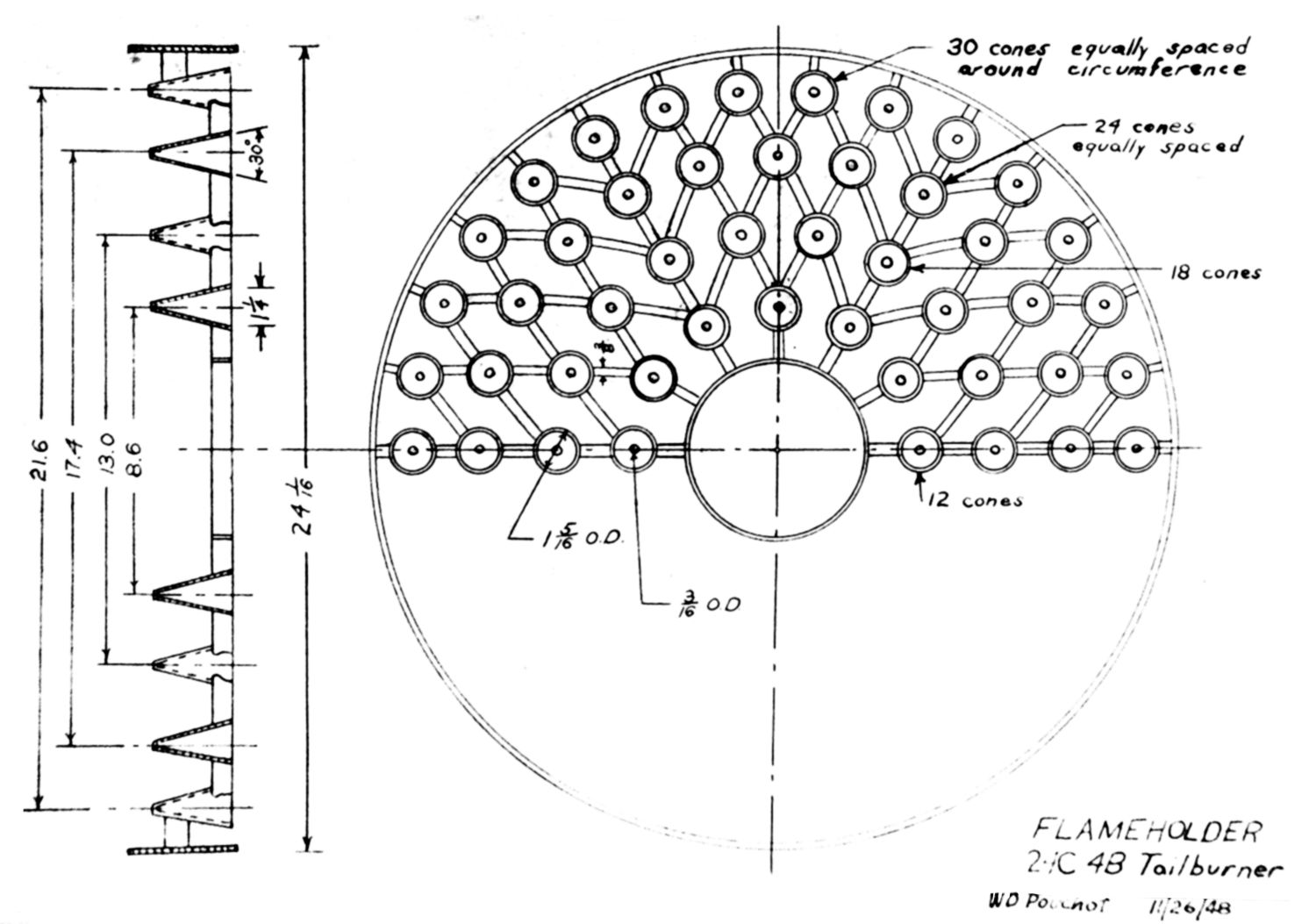
4. The tubular flameholders were made of AN‑WW‑T‑831 of 1.5" diameter with a 0.49" wall.
5. A mounting lug to be attached to the airframe via a roller and track assembly allowing the cylindrical band around the combustor can to be moved into the correct position for that airframe was included. Later a quick disconnect joint would be designed.
6. Cooling was a challenge and after considering other methods and rejecting them for either cost or weight, an external ejector was selected. It offered lighter weight, ease of fabrication and the possibility of obtaining a thrust boost in certain flight conditions. A baffle was placed in the ejector air flow which directed part of the air down under the moveable lid even when the lids were fully open.
7. The eyelid nozzle electric motor was mounted on the bottom for cooling and space reasons. For the F-80A it was turned on its side to remove an interference. It drove screw jacks on the side of the burner; these operating the side swinging eyelids via a flexible cable.
8. The controls were covered in Report A-770 (above).
9. Manufacture was found to be easy. Flanges were made on the fuel tubes and tubular flameholders in 18-8 stainless steel to speed manufacture. Several external bosses were also made from 18-8 due to non-availability of the better material. The eyelids were spun as one piece and then cut, eliminating a butt-weld, which would have been a source of weakness.
Initial testing results:
No. 1 Design – Testing began on March 11. Difficult vibrations and thermal expansion problems were encountered. Repeated cracking of fuel tubes and splitting of the combustor casing occurred. Ignition was very good with the burner lighting at any rpm and with the exhaust area wide open.
No. 2 Design – This was a complete assembly including eyelid nozzle afterburner dump valves and an ejector with all parts annealed. Previously used parts were repaired and runs made on 7 May. The porcelain insulator pushed out to the internal pressure in the diffuser and the AB dump valves leaked into the burner during normal engine operation. The porcelain of the inner spark plug became loose and travelled upstream and lodged between the first and second turbine discs. At that point the compressor failed while the porcelain was still in the turbine, causing an imbalance of the turbine and causing a compressor blade rub. The eyelids had worked very satisfactorily. A metal collet (collar) was added to the porcelain insulator so that it would remain stationary and the inner spark plug was welded to the frame to stabilize it. The dump valves were eliminated and the burner operated again on 14 May. Ignition was OK at first, then became poor. Arcing was found and eliminated. Operation continued until the rear end of the diffuser cone broke loose. The turbine locking ring was warped and buckled from heat. A backflow of hot gas through the hole in the inner cone was occurring against the turbine. Repairs were made and testing resumed on 22 May, but a fuel tube broke before ignition occurred. The 0.125" diameter tubes were determined to be impractical.
Design No. 3 – The burner was abandoned for the time being and the No. 3 design was used. This had a smooth diffuser with no stepped flameholders but with a tapered center cone. The fuel rings and flameholders were both located in a twelve" long cylindrical section which could be easily removed and repaired. The combustor casing and eyelid nozzles were consistent with the prior design. The ejector had seven inches added to the leading edge. The fuel rings were now five concentric tubes of 0.250" diameter. The flameholders were now 1.5" diameter tubes. The spark plug was located inside the inner flameholder without any special ignition fuel nozzle. Non-AB thrust loss was found to be 10 percent, excessive, but credited to the sound suppression test house muffler which was out of position. After six minutes of operation the combustor casing cracked and a squeal was heard during the fuel rate increase, but both ignition and eyelid operation were satisfactory. Some localized failures were found on the diffuser struts, the casing around the spark plug and the clips holding the ejector. Various repairs and changes were made but not enough fuel could be admitted to give the required thrust boost of 30 – 40%. With fuel flow at 7,000 lb/hr a boost of 31% was achieved with an SFC of 2.7 lb/hr/lb. Thrust loss was still 10% even with the muffler in the correct position. More combustion damage occurred as various changes were made. At that point on 30 June, testing was stopped until a solution to the squeal issue was resolved.
The third report (A-785, 20 December 1948) gave some of the history of the first experimental ABs supplementing data reported in A-781. Given how far WAGT was in developing the Model 3 by January 1949 when this report was received, the information was of historical use to BuAer only.
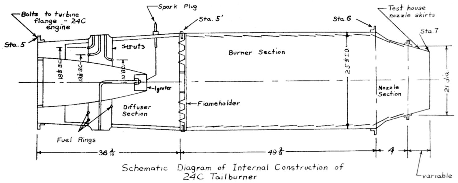
Fig. 9. WAGT Experimental Model 1 AB Layout. The Model 1A differed in not having a liner, which resulted in increased thrust because of the higher temperature operation possible.
Fig. 10. Model 1 Flame Holder for the 24C-4B Based on Work at the Massachusetts Institute of Technology.
Model 1 testing showed that the durability of most parts was satisfactory during 80 minutes of wet operation and 626 minutes dry. The AB started consistently from 10,000 to 12,000 rpm and occasionally up to 12,500 rpm when a 306 in² nozzle was used. Vibrations were not noted except at shutdown. Squeal was heard when the fuel was shut off, the sound likened to that of tires during an emergency stop. At that point, the cause was unknown. Combustion efficiency was between 90 – 100% and wall cooling problems were not encountered. The four-foot cooling length was found to be undesirable. The design required very good pressure recovery in the AB diffuser thus requiring that part to be very long. Too much attention to burning efficiency had been paid at the expense of length, weight, pressure loss, and structure. The Model 2 had a shorter burner length and simple, sturdy flameholder with less blocking of the air flow and a shorter diffuser.
WAGT AB Performance at Military (12,000) rpm
Non-Afterburning
Afterburning
AB Model
% Pressure Loss
% Thrust Loss
% Thrust Increase
SFC
Gas Temp°C
No. 1
7.5
7.1
29
2.42
1,599
No. 1A
6.0
5.7
36
2.44
1,737
1 November 1948: WAGT copied BuAer with the specification above and referenced Contract NOa(s) 9670 (for the J34-WE-32, -38 and J46-WE-2), stating they wished to continue AB development under that contract.
11 November 1948: Progress Report A-770 covering Project 839, the control system for the AB.
[Author's Note: Text below taken from Westinghouse J34 Axial Turbojet Family, Development History and Technical Profiles, Chapter 9.]
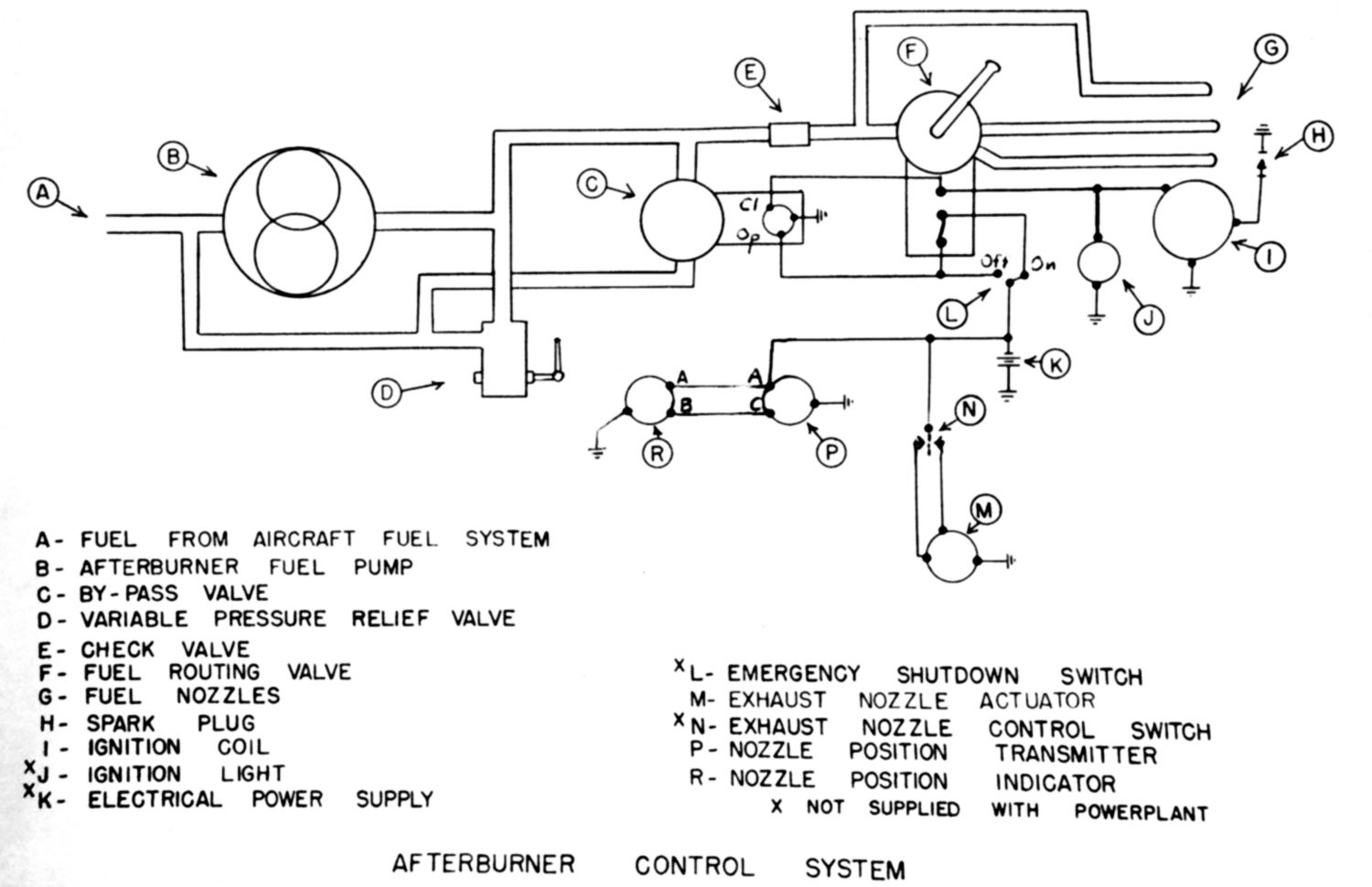
After initial studies were complete, it was determined the development should progress toward automatic scheduling of an optimum fuel/air ratio in the AB while maintaining the peak turbine temperature by modulation on an infinitely variable exhaust nozzle while providing the pilot a means to establish the desired percentage of thrust augmentation by manual selection of fuel routing to the afterburner fuel manifolds. (Note: If achieved, it would give the pilot some level of variable AB thrust, not just an on/off option. – Auth.)
It was decided to develop a fuel system that could maintain a given fuel pressure for a given measure of mass air flow, thus keeping the AB fuel/air ratio within the limits of stable burning over the anticipated flight conditions for partial as well as full augmentation. A parallel development of an automatic engine exhaust nozzle was underway, so Project 839 focused on a manually controlled electric actuator to the exhaust nozzle to be used on the first development AB. The work was completed on schedule and formed the groundwork for the detailed design of the fully automatic systems for the J34-WE-32 and J46 afterburners.
As developed for the initial prototype, the engine power control only held the Military rpm of the engine and peak turbine outlet temperature at constant values through coordinated regulation of engine fuel and modulation of the exhaust nozzle area, irrespective of any variations in AB operating conditions. The exhaust nozzle area was adjusted by the pilot in accordance with temperature indications on a cockpit instrument. The control used a toggle switch operating an electric actuator linked directly to the exhaust nozzle eyelids. This would later be replaced by a hydraulic exhaust nozzle actuator eliminating the need for the separate cockpit control.
It was found to be necessary to arrange for admission of fuel to the afterburner in progressive steps starting with the innermost manifold and then all the manifolds for full thrust. Fuel pressure rather than fuel flow was scheduled in the fuel regulator to avoid complexity. The result was the ability to cut out groups of fuel nozzles without upsetting the local fuel/air ratios in the afterburner. In the prototype, the AB control system was provided with a fuel pressure regulator which automatically maintained the manually-selected fuel pressure settings irrespective of the degree of thrust augmentation selected. A separate fuel source next to the spark plug was found to be unnecessary. The continuously operating ignition coils proved capable of maintaining a continuous spark during the entire period of afterburner operation.
Available air-turbine driven fuel pumps were not adequate without modifications. Special engine driven gear type pumps of 13,000 lb/hr capacity were provided for the first two J34 development ABs.
It was determined it would be possible to use the planned J34-WE-32 and J46 power controls interchangeably on AB and non-AB burning engine variants. Further development would be concentrated on the AB fuel regular and afterburner fuel pump in Project 962.
Fig. 11. J34-WE-11 AB Fuel Control Schematic. WAGT Report A-770. Courtesy Hagley Museum and Library
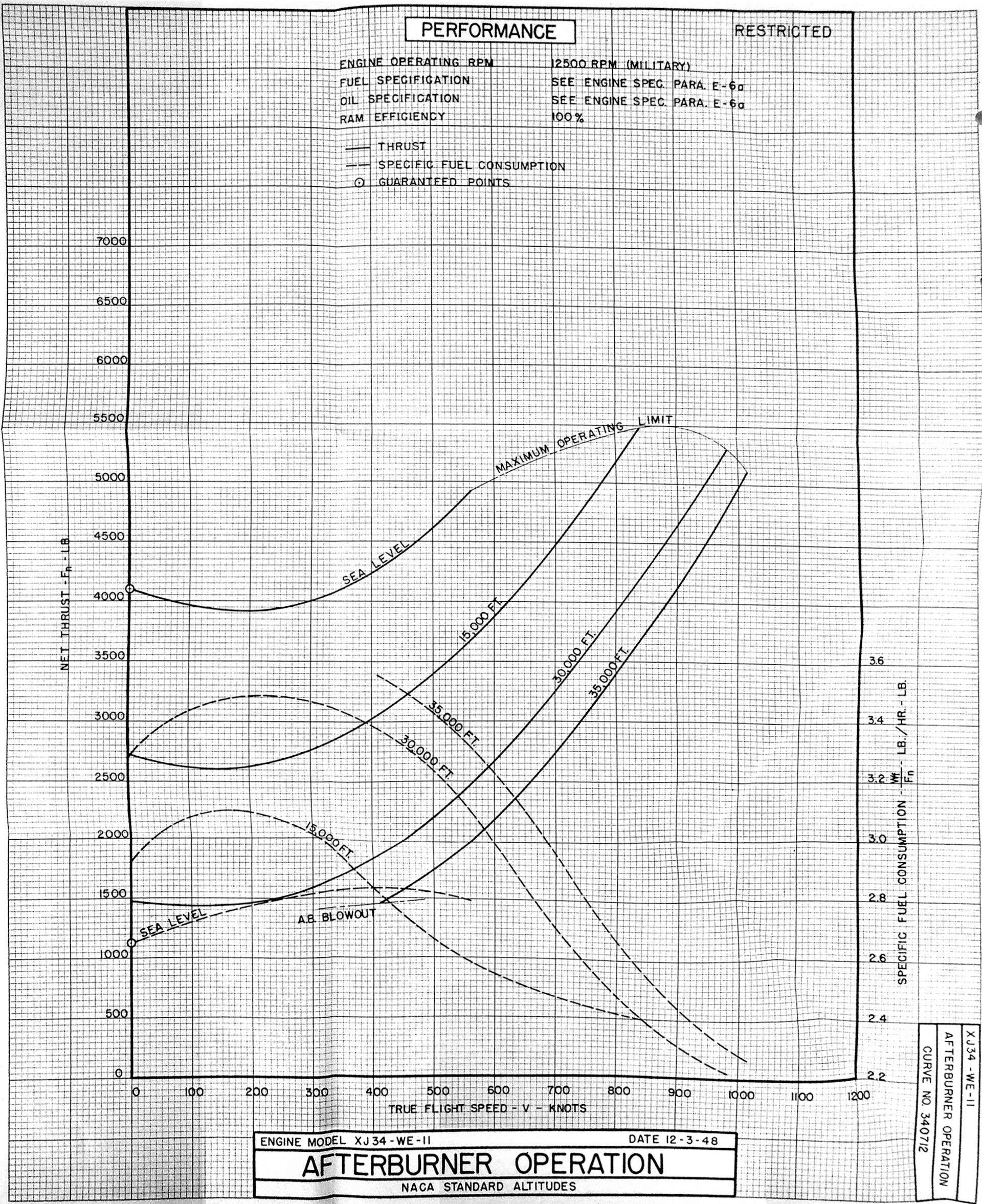
13 December 1948: The various performance and thrust curves for the engine specification were submitted to BuAer. The basic engine at that time was to be a production J34-WE-22 and the sea level thrust with the AB installed dry was reduced from 3,000 to 2,900 lb (-3.3%) but with the AB wet the thrust was 4,100 lb (+41.3%). With work on the XJ34-WE-32 engine and its afterburner underway, the Air Force designated XJ34-WE-11 model can be seen as an intermediate stepping stone to meeting the full BuAer requirements for the XJ34-WE-32.
3 January 1949: BuAer finally sent a long-winded response to WAGT regarding their desire to move the AB development over to the NOa(s) 9670 contract. Netting down this response to a few points, we find them to be:
1. The project was planned by WAGT to culminate in Specification WAGT-X24C5-2 dated 1 September 1948 and produce four reports (not yet delivered.). (Covered earlier above– Auth.)
2. The work to date had produced only intangible results for the Navy. The Air Force, on the other hand, had a WAGT afterburner available for F-80(A) flight tests and an improved semi-automatic control unit expected from WAGT before the end of 1948 for the XF-90 airplane with further improvements to be delivered when available.
3. Air Force funds under a separate contract had paid for the AB work for the F-80(A) and XF-90 (The reference contract not identified.)
4. The Navy’s XF7U-1 needed afterburners and the WAGT’s AB work was intended to provide engine and AB control improvements for that program. (No documents have been found stating that objective was ever communicated to WAGT before.)
5. The development of the XJ34-WE-32 and XJ46 engines would not provide suitable (AB) units until late 1949 and even then, would not be readily usable with the engines currently assigned to the XF7U-1 program.
6. The engine components available for the XF-90 and F‑80(A) should be equally available and adaptable to the XF7U-1 airplane and should be available well before the results of NOa(s) 9670.
7. It was reasonable to continue the program under NOa(s) 5382 until the improved control systems were available for use in the F-80(A) test program but not later than 30 June 1949.
8. Transferring the contracts would not ensure that the control systems were available for test in the Naval Aircraft except at the much later delivery dates of NOa(s) 9670, therefore the contract transfer request was denied.
9. To prove the control was suitable for use in the XF7U‑1, WAGT should furnish, under Contract NOa(s) 9670, two sets of control systems of the type developed under NOa(s) 5382 and supplied to the Air Force. The systems should be suitable for the XF7U-1 airplane with J34-WE-22 engine in flight. Any increased anticipated cost for the systems should be relayed to BuAer before 15 January 1949.
10. The systems would be tested and if effective they might be flown in the Chance Vought aircraft. Afterwards they would be returned to WAGT for further use under contract NOa(s) 9670.
BuAer requested information at an early date on the flight articles experience and anticipated results of the planned program as well as the four reports, with flight experience reports at the end of each third of the hours of the expected flight program for the F80(A).
10 January 1949: Delivery of the final report, A-795, covering AB durability. (Report not found.)
12 January 1949: A WAGT memo covering modification of J34 engines to accommodate afterburners was received. This reminded BuAer of all the reports sent to date on the AB project and indicating they would be reporting further progress under NOa(s) 9670. It included some interesting information about the AB and engine modifications not contained in the A‑796 report to come.
1. The XF-80A-2 installation included a variable augmentation AB and AB control.
2. Operations (in addition to the engine control) required of the pilot were selection of a manifold percentage, manipulation of the exhaust nozzle area control, and manipulation of a fuel pressure regulator.
3. Engine modifications were included:
a. Test sample R-46 flyball governor
b. J34-WE-30 compressor
c. J34-WE-30 turbine nozzles
d. J34-WE-30 turbine blades
e. Quick disconnect features
f. Compressor air bleed manifold
4. The engine/AB combination was the same, except for a barostatic device to be added to the AB control, planned to be provided for the XF-90 program to obtain test information useful for the XJ34-WE-32 program.
5. Since the F7U program needed a more automatic AB than was being developed under NOa(s) 5382, BuAer was requested to reconsider their plan of continuing the program under NOa(s) 5382.
20 January 1949: Report A-796 under Contract NOa(s)-9670 was sent to BuAer. It covered the first eight flights of the F-80A-2 with the XJ34-WE-11 installed and operational. The key test results were:
1. The ground calibration test of the engine and AB duplicated the test cell calibration measurements after accounting for the airframe duct losses.
2. The total AB and controls weight was 340.9 lb. Installed in airframe it was a net 275.2 lb because of the items removed from a standard engine for AB installation, these being exhaust collector, eyelid nozzle, electric actuator motor, screw-jack, rods and flexible cable.
3. The AB was operated up to 35,000 ft successfully.
4. Relights up to 20,000 ft were normal, above that it was necessary to juggle the AB fuel rate, engine rpm, and the eyelid nozzle position up to 30,000 ft.
5. Relights above 30,000 were not tried.
6. The spark plug was not needed at higher altitudes, accelerating the engine ignited the AB.
7. Full power AB runs were made up to 35,000 ft with no blowouts or blowout tendency being detected.
8. On the eighth flight, the AB was started with the eyelids accidentally left in the closed position, over-temping the turbine. A landing was successfully made and broken turbine blades were found to have lightly damaged the AB.
9. Further flights were planned after the engine was repaired.
Other development work underway described in the report:
1. Hot streak ignition – with injection just ahead of turbine, no AB ignition had resulted. The injector was moved to the compressor outlet location and streaks of flame five feet long were then observed behind the turbine. If it worked with the AB, the spark plug and coil could be eliminated.
2. A splitter was tried to improve non-burning thrust loss – no gain noticed.
3. Structure – The flexible flameholder was found to be too weak for the severe combustion pulsations. All parts were found to have been pinned or hinged in the AB.
4. Scale Model Tests – Showing burning efficiency would be critical with AN-F-58 (JP-1 fuel) because it reached its peak burning efficiency at a lean air/fuel ratio and did not allow the burner to reach the high burning temperatures required for high thrust augmentation. (Note: BuAer was trying to move all jet projects from avgas to AN-F-58 type fuels. Currently, the J34-WE-22 ran on avgas but was being tested on AN-F-58 prototype fuels to determine what problems might be encountered.)
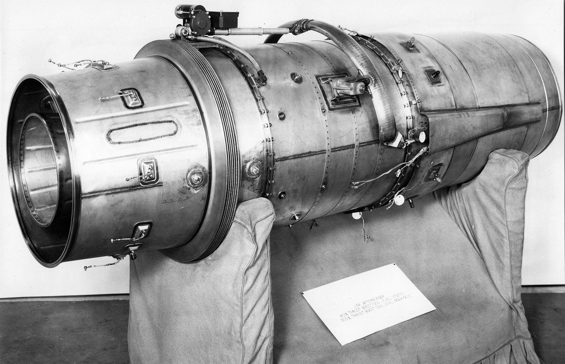
Fig. 13. Thought to be the Model 3 AB Used at Lockheed in the F-80A-2 project. The Model 4 was very similar and used in the Lockheed XF-90 program. Card reads “J34 Afterburner, 40% Thrust Boost at Sea Level. 300% Thrust Boost at Mach No. 2”. WAGT P40525, 24 February 1949. Courtesy Hagley Museum and Library
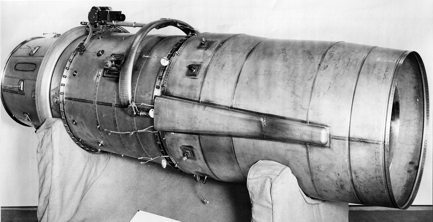
Fig. 14. Side View of the Same AB. WAGT P40525, 24 February 1949. Courtesy Hagley Museum and Library
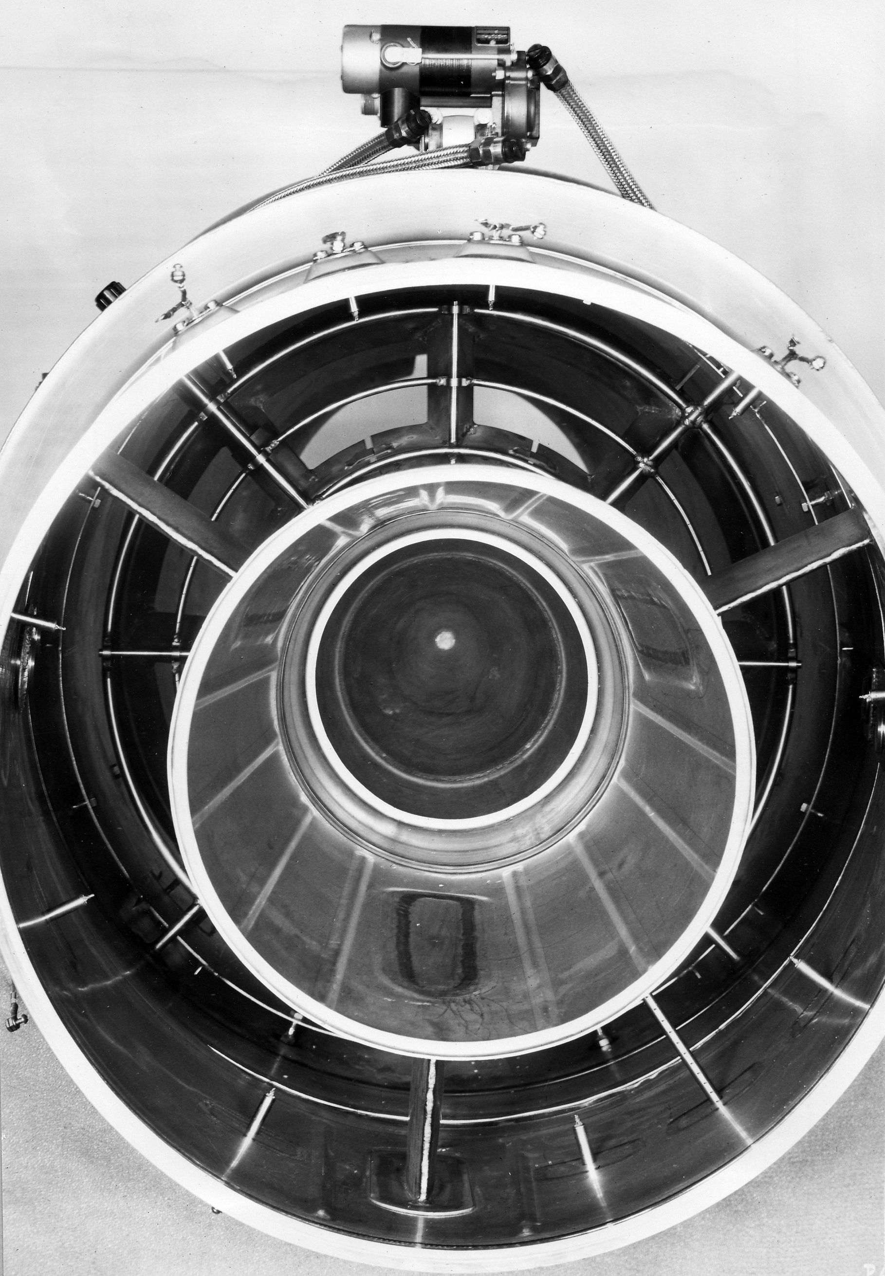
Fig. 15. Model 3 Diffuser Intake End. WAGT P40532, 24 February 1949. Courtesy Hagley Museum and Library.
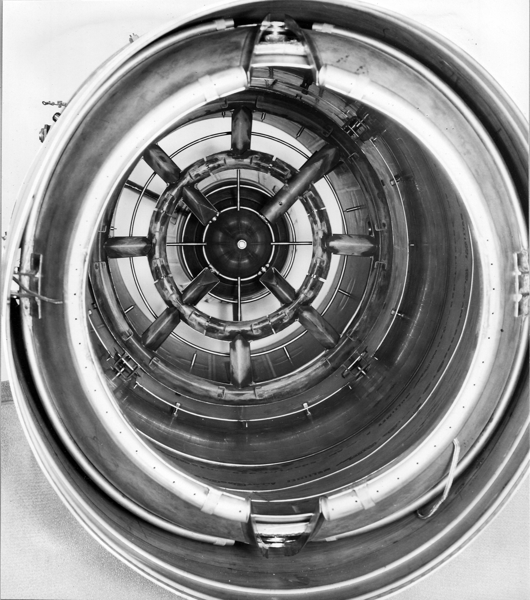
Fig. 16. Model 3 Exhaust Nozzle End. Note eyelids are partially open. WAGT P40533, 24 February 1949. Courtesy Hagley Museum and Library
20 January 1949: Report A-796 Contract NOa(s) 9670 included the information that eight “production” ABs were under construction with the first to be completed by 4 February 1949. Two were to be assigned to the 24C8 (J34-WE-32) program development testing and the balance to be shipped to the XF-90 flight test program.
25 January 1949: The Air Forced asked that the engine’s continuous power operating limit be raised from 15 to 30 minutes for the XF-80A-2 test program. WAGT approved the increase and also increased the continuous operating limit time on the AB from 5 to 10 minutes. BuAer also approved. These extensions were intended to allow the project flight tests to reach higher altitudes and obtain complete equilibrium of flight variables which suggested they only be used when necessary.
Although the J34-WE-22 was only qualified with a 15-minute Military test time limit, such an extension of the continuous military time had been granted to the Douglas D-558-II project and such extended operation was not considered hazardous by WAGT when accomplished at medium and high altitudes.
18 March 1949: BuAer finally responded to WAGT’s 12 January memo. They noted that although some detail objectives of the program had not been achieved, the balance of the work reported was all within the scope of the contractor’s outline. However, the reports made no mention of the overall objective quoted in their 8 December 1947 proposal. Apparently, all the efforts had been devoted to design and construction of a workable AB system specifically toward immediate application in the F-80 and XF-90 airplanes and also the contract NOa(s) 9670 afterburner development. BuAer requested that a report summarizing the degree of attainment of the overall objectives be submitted in addition to the reports already submitted and the specification WAGT-X24C5-2 written under the program.
The general description contained in the proposal regarding the type of afterburner control system actually developed for the F-80 and XF-90 airplanes was not sufficient to enable BuAer to determine whether or not that system was superior to the Solar ABs in use in the F6U-1 and XF7U-1 airplanes. A detailed description of the XF-90 control system was requested before the earlier request for two sets of the developed control systems could be reconsidered. “Until acceptable information requested (above) is presented, transfer of afterburner and associated engine modification materials from contract NOa(s) 5362 to contract NOa(s) 9670, as requested, is not authorized.” As will be seen a bit later, many changes to the design of the J34-WE-32 AB control came about at this time as responses to the -32’s mock up board suggestions were worked through.
28 June 1949: Issue of Report A-863 – Modifications to J34-WE-22 Engines to Accommodate an Afterburner, Contract NOa(s) 5382. This report listed five things done to adapt the J34-WE-22 for AB attachment and use:
1. The rear turbine casing flange was eliminated and a quick disconnect coupling was provided for connection to the AB.
2. A flexible joint was designed into the AB so that deflections of the burner relative to the engine would not impose excessive loading on either the engine or the afterburner.
3. A variable area exhaust nozzle and actuator together with all linkages were designed to achieve the range of exhaust nozzle area required for engine and AB operation.
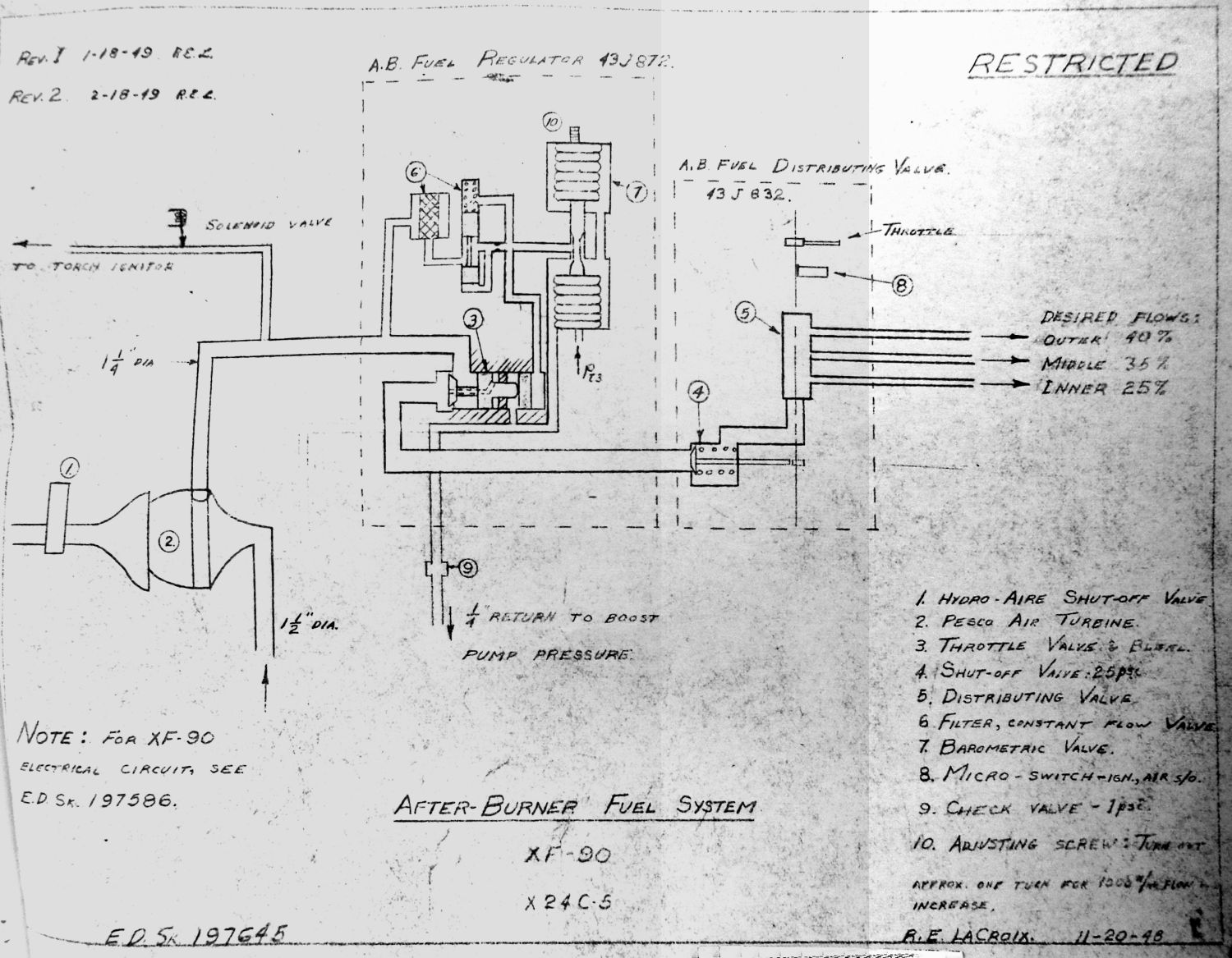
4. An AB fuel control system was designed and incorporated on the engine. This consisted of an air shut-off valve, an air turbine driven fuel pump using compressor bleed air, a fuel pressure regulator, and a fuel routing and shut-off valve. Those parts together with suitable piping were located on the engine casing.
5. An AB ignition system called a “torch-ignitor” was provided. This included a spray bar inserted in place of one of the engine spark plugs, another spray bar located in the AB diffuser to relay the hot streak down to the burner flameholders, and a solenoid for controlling the fuel flow to the spray bars.
With the modifications above, the AB became the Model 4 and successfully completed an endurance test that included two hours of operation.
29 June 1949: Issue of Report A-864 – Afterburner Fuel Control Development Contract NOa(s) 5382. The report included a schematic sketch of the control system that met the requirements of an automatic control system permitting selection of partial augmentation by the pilot, the latter having been demonstrated in flight tests. It was felt it lent itself more readily than any other known type to adaptation to future engine models with electronic governing system (planned for the J34-WE-32, -38, J46 and J40 engines) to provide maximum thrust augmentation with maximum combustion efficiencies.
Fig. 17. AB Fuel Control Schematic as Used in the XF-90 Flight Test Program.
For the XJ34-WE-32 program, the manual fuel pressure regulator was replaced with an automatic barostatic device. The -32 design would also include an emergency system to route fuel from the main engine fuel pump in case of failure of the AB fuel pump or fuel pressure control elements.
The report included a comparison to the Solar fuel control system. It stated its main drawback was that at higher altitudes, increasing amounts of fuel were required to achieve a given temperature rise and consequently the fuel consumption might increase out of proportion to the additional thrust obtained.
The WAGT system was predicated on meeting the following conditions:
1. AB would be employed only after maximum Military thrust had been obtained from the basic engine, i.e. at Military rpm and maximum turbine-out temperature.
2. The AB would operate at optimum efficiency under all conditions of ram and altitude at which the AB was operable.
3. Partial, as well as full thrust augmentation, would be available under all flight conditions at which the AB was operable.
To meet condition No. 1, mass air flow through the engine had a linear relationship with the compressor outlet total pressure, which considered air speed, temperature and altitude. Outlet pressure was selected as the basis for scheduling fuel to the AB.
To meet condition No. 2, an infinitely variable-area tail was believed necessary, utilizing the fuel control to maintain optimum fuel/air ratios. It would provide the maximum range of operating conditions and maximum combustion efficiency, both the basic engine and the AB. It was noted that the performance guarantees for all the new engine designs under development for BuAer were based on the utilization of an infinitely variable exhaust nozzle for the basic engine.
To meet condition No. 3, fuel flow by means of pressure regulation was necessary. Thus, as any desired portion of the total number of manifolds was selected, the proper fuel/air ratio for the manifolds still operating could be maintained automatically.
Based on the above, WAGT felt that their control system best met the requirements for an AB with a variable-area exhaust nozzle where partial thrust augmentation was desired.
10 August 1949: BuAer acknowledged receipt of the reports, reminding WAGT that they had suggested the basic engine control be revised to provide a fully automatic engine-AB control along with full protection against exceeding the safe operating limits of the basic engine at all times.
BuAer would not consider the program complete until:
1. The engine modifications necessary to permit successful operation with an AB had been completely defined, and
2. The final WAGT AB and control system developed had been sufficiently described to enable a final evaluation by BuAer as to the feasibility of using, if necessary, the WAGT AB in lieu of some other design on aircraft using the J34-WE-22.
BuAer requested all modified drawings and the updated specification. BuAer stated that the subject program had not been carried out to the extent envisioned by the WAGT proposal. Further investigation under the subject contract (NOa(s) 5382) was not requested and the request for two control systems was cancelled. Until the materials and response were received, the transfer of government owned material to contract NOa(s) 9670 was not authorized.
21 October 1949: WAGT forwarded to BuAer a memo on modifications needed by the J34-WE-22 in an effort to resolve the impasse and gain the Power Plant Division’s approval. Attached were copies of the Specification WAGT-X24C5-2A dated August 26, 1949 and copies of five drawings (not retained).
Data on the endurance test the engine with AB had completed was included.
1. The engine was submitted to 24 10-minute cycles of 5 minutes afterburning at full actual Military (12,500 rpm) with the gates (eyelids) wide open followed by 5 minutes of non-afterburning at Normal power (11,800 rpm).
2. Measured thrust was 1% in excess of guarantee and was developed at an SFC 13% lower than guarantee.
3. During post-test teardown, two defects (minor) that would not affect flight safety were observed:
a. The flameholder was cracked.
b. The gate seal was cracked.
4. No apparent adverse effect on engine life was observed or expected from the defects or from AB operation
27 October 1949: The BARR’s forwarding memo added some further details. The 4-hour endurance test had actually been done as a development project under Contract NOa(s) 9670. The BARR was not informed of the start of the test and the defects resulting from the test were not on display for the BARR to review. (This was an Air Force Project.) The WAGT XJ34-WE-11 engines supplied to the Air Force had considerable trouble in that the flameholders, diffuser struts and the eyelid seal had cracked during the acceptance test. Thrust in both non-AB and AB operation had been borderline to the guarantees. SFCs were about 10% below the guarantees.
14 December 1949: BuAer HQ accepted the information received as answering the open questions and considered the objectives of the program as having been generally met. Transfer of residual AB and associated components to NOa(s) 9670 as GFE was authorized. A list of the items transferred was requested.
16 December 1949: In a USAF memo covering the Model XF-90 Flight Test Progress Report 14, it was stated that the XF-90 used the J34-WE-22 engines WE020016 and WE020019 modified with WAGT ABs to the J34-WE-11 configuration. The engines ran reliably for the most part in limited flying but Lockheed discovered the basic engine thrust with the AB attached but not operating dropped 14%. Phase I testing was forced to use the North Field at Muroc due to extremely wet conditions on the lake bed. To attain acceptable takeoff conditions on the shorter North Field airstrip, the ABs were removed and JATO bottles used to supply the missing thrust. WAGT engineers installed improved seals around the AB eyelids and the ABs were reinstalled for the Phase II testing. Total Phase I and Phase II flying time was about 40 – 50 hours across both airframes.
27 January 1950: The list, which shows two (2) complete AB assemblies and a variety of modified engine parts, was delivered to the BARR on January 27, 1950.
At this point, all development attention was now on the other Westinghouse contracts that were to use ABs. These were the J34-WE-32, the J46-WE-2 and the J40-WE-8/22 and their complex and intertwined development histories will be covered next.
[End Part 4a of the Early US Navy Afterburner Development Efforts – Westinghouse Electric Company]