Early U.S. Navy Afterburner Development Efforts Part 3f: McDonnell Aircraft Corporation – Final Tests and Project End by Paul J. Christiansen Published 27 Jul 2026
Part 4c: Westinghouse Aviation Gas Turbine Division (in process)
Part 4d: Westinghouse Aviation Gas Turbine Division (in process)
McDonnell Aircraft, St. Louis, Missouri
8 September 1950: Contract NOa(s) 9022; Afterburner Progress Report 6 June to 5 August 1950.
McDonnell reported on the additional AB development program using ground and airborne F2H-1 testing. The JA34‑MD‑16 model ABs were used during the larger part of the program. One successful ignition was accomplished at 44,000 ft and continued satisfactory operation at 48,000 ft as well, the thrust levels obtained were delivered in Report S‑239 and in the revised 29 November 1949 version (not found). From an endurance standpoint, the AB and controls had been adequate for flight test development. Minor cracks in the AB forward section and AB nozzle expander seal failures had been the major structural problems. Certain components in the control system had only a limited life, but appeared to be amenable to minor modification and testing. The AB operation time that was accumulated was: Flight – 63%, Static tests – 31%, NACA altitude tests – 6%. One AB had now reached an operating time in excess of 105 hrs and four ABs had experienced more than 5 hrs each.
JA34‑MD‑16 Development:
1. Several minor redesigns had been made to the combustor to eliminate cracks that developed in arc‑welds on the divider and at the intersection of the divider and the struts. Structural analysis showed a redesign of the divider attaching method was required.
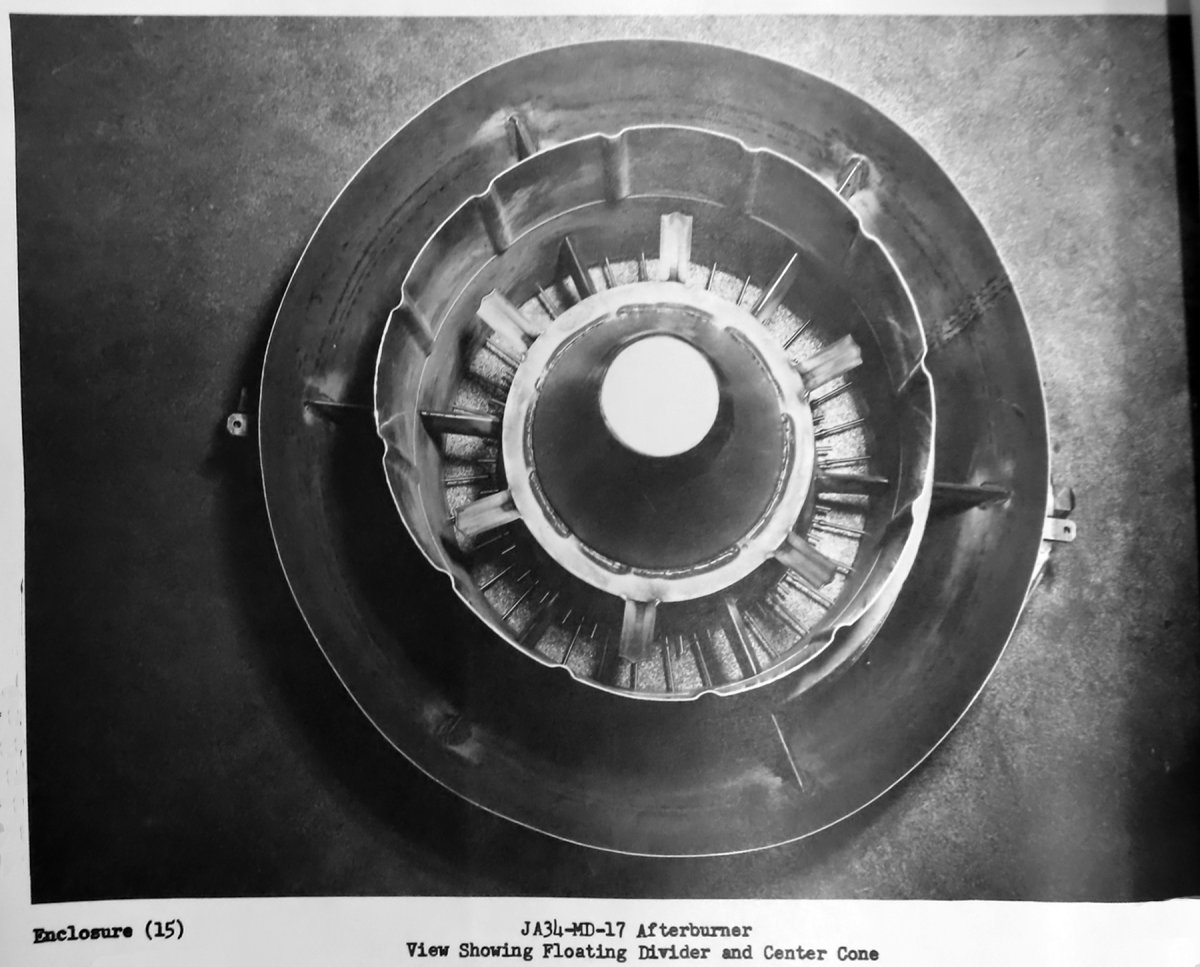
a. Elimination of the cracking condition was attempted in the ‑16 model. The new design was an integral divider and flameholder structure with a floating joint at the struts. The welding at the divider leading edge was replaced by a spotwelded junction.
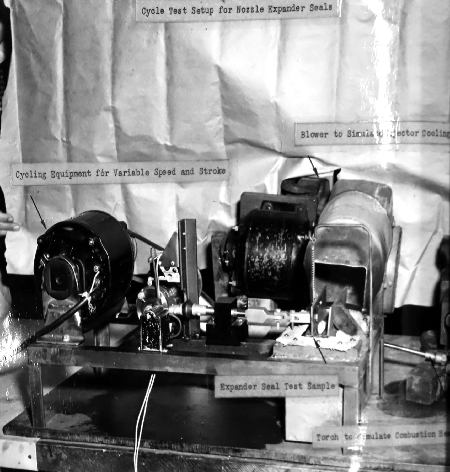
b. The nozzle expander seals would not give the required endurance in service use, the current life was about 5 hrs of wet operation and 75 – 100 hrs dry. The problem was a material fatigue failure. Alternative designs had been developed and would be tested using simulated temperature and operational cycles on a nozzle expander testing machine.
c. The automatic control would be improved using:
i. Thermocouples with more rapid response would be used to eliminate a tendency of the current control to become unstable when adjusting for rapid nozzle area response to TOT changes.
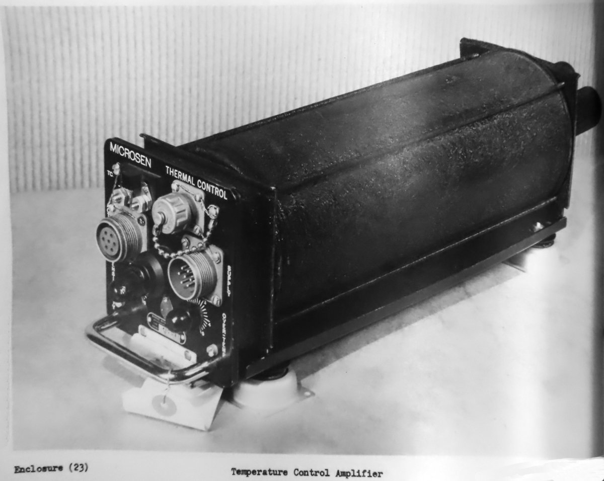
ii. An improved temperature control amplifier was being investigated along with the possibility of eliminating an intermediate temperature control servo motor. Everything would be consolidated into a simple control box that would contain all of the AB sequencing relays.
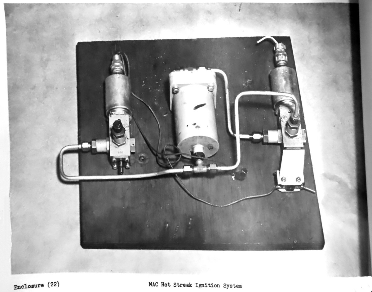
d. Two new methods of providing automatic hot streak ignition were being investigated. The first would keep the current design with the hot streak pump being redesigned to incorporate a single control valve as an integral portion of the assembly in place of the separately‑mounted control valves in the current design. The second method would eliminate the hot streak pump completely and employ a small motor‑driven valve that would be accurately timed to give the designed delay and duration of the hot streak fuel injections.
e. A more reliable AB air‑turbine fuel pump would be tested.
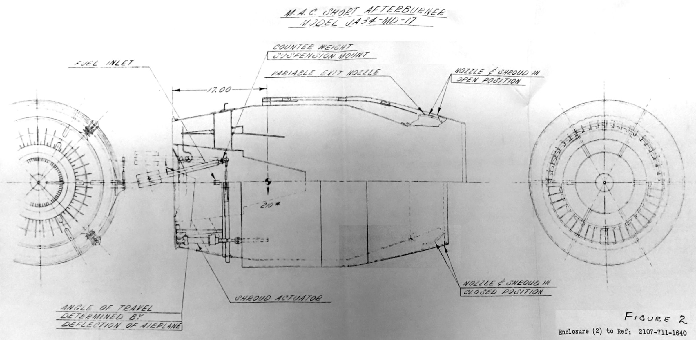
2. To reduce weight and improve simplicity, a new AB structure was being designed for testing. The new model was the JA34‑MD‑17. It would retain all of the desirable basic design elements of the JA34‑MD‑16 and offer the following improvements:
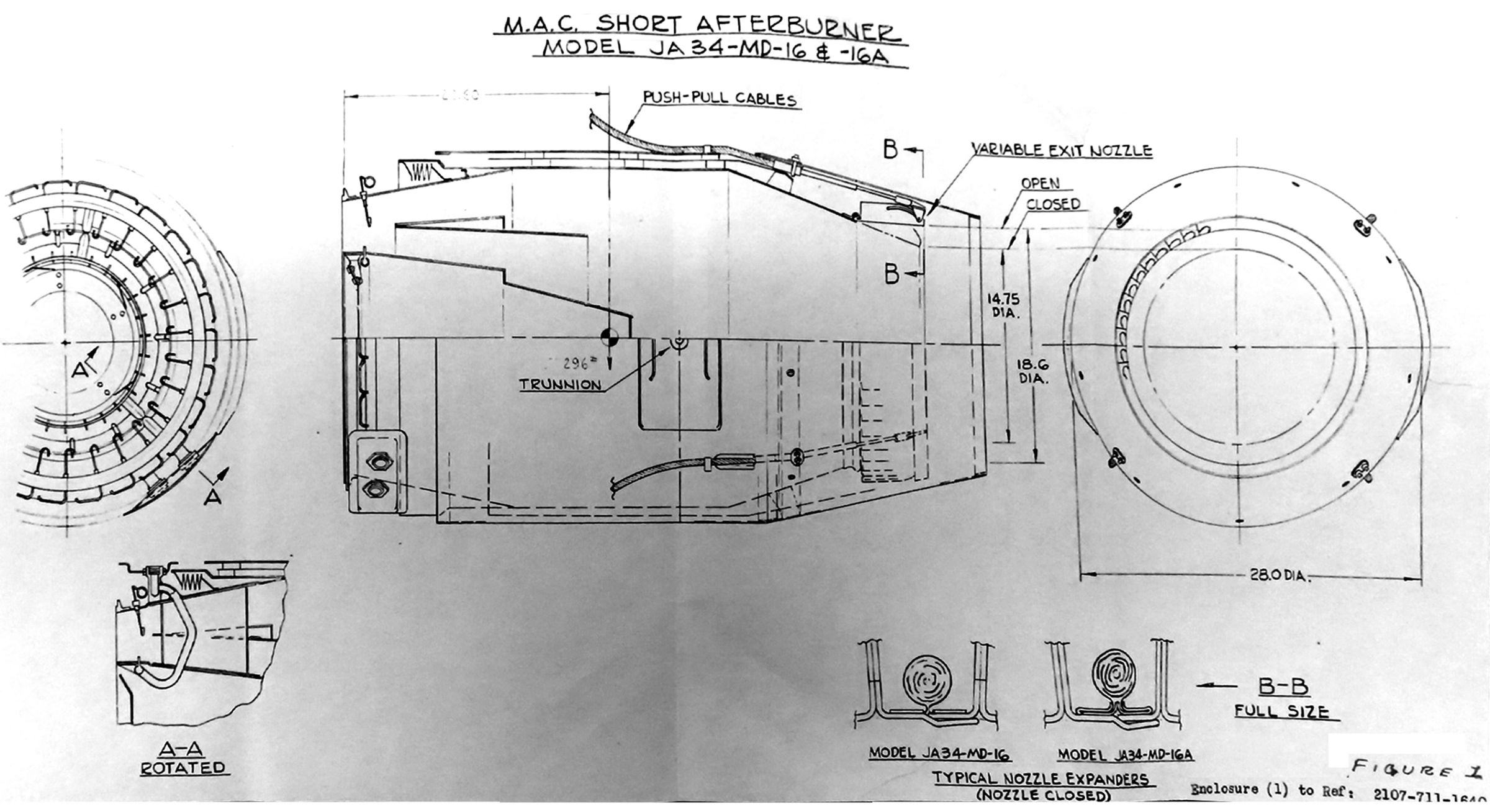
a. The nozzle actuating push‑pull cables were eliminated and a movable shroud to open and close the exit nozzle was incorporated (See Fig. 1).
b. The AB suspension method eliminated an alignment bellows and simplified the shroud design by removing suspension loads from that part.
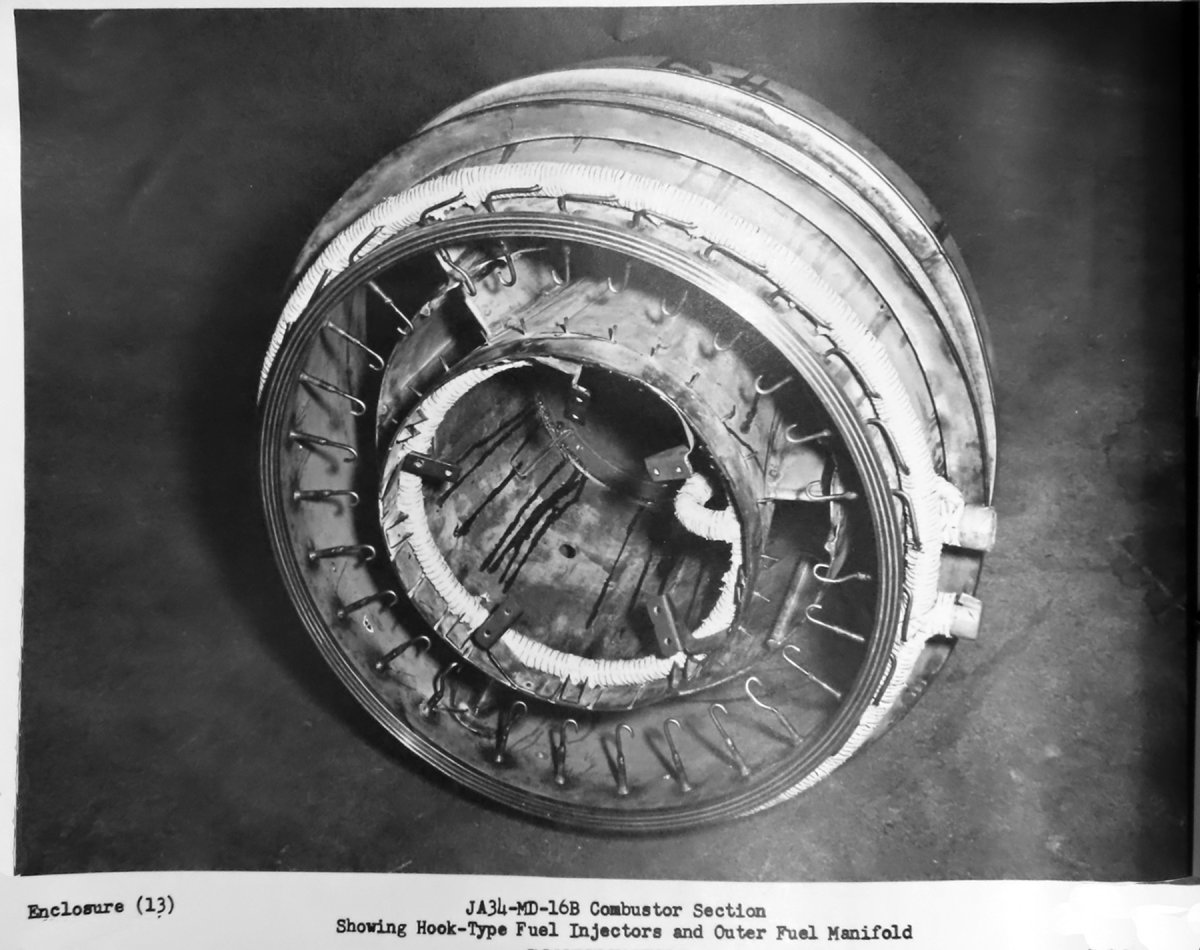
c. The external fuel manifold was moved to the burner interior for simplicity and the elimination of damage risk to external burner parts through mishandling.
d. The new model projected weight would be approximately 70% of the ‑16 design.
e. The combustor was redesigned to eliminate the thermal and fatigue cracks experienced in the ‑16 design. The divider and flameholder were now made up as a box beam with floating joints at six struts; these reduced to less than half the size of those in the ‑16. The new strut design was expected to improve the AB skin and exit nozzle temperature pattern and permit higher temperatures. The divider was extended forward in order to take advantage of a possible improvement in diffuser efficiency. The divider was also extended further aft behind the flameholder in order to check the effect of a hot surface on combustor efficiencies. The flameholder step was increased from 1.000" to 1.125" in order to improve high‑altitude performance. The fuel injection system was redesigned so that fuel penetration and different types of fuel injection could be varied for tests.
f. The basic contours of the exit nozzle were retained, but the actuating cam surface was raised and lengthened in order to obtain lower actuating loads and better control sensitivity. It was planned to modify the expander seals upon the completion of tests to determine the optimum diameter, endurance, and material. The nozzle segments of the first test burner were fabricated and drawings for precision‑cast segments were released.
Fig. 1. JA34‑MD‑16 Blueprint with Typical Nozzle Expanders
Fig. 2. New JA34‑MD‑17 Blueprint
Fig. 3. Seal Expander Test Rig
Test Results:
1. One of the ‑16 ABs was modified to the new floating divider design. Tests on both the static test stand and in flight appeared to confirm that the structural failure issue was solved. Testing on the ‑17 was to start as soon as it was available at Westinghouse and further testing on the ‑16 redesign was stopped.
2. The status test setup had been modified to test the seal expander endurance properties. Testing would emulate the seal cycle life under simulated nozzle operating deflections and temperature.
3. Static and flight tests on control modification would be started during the next report period, beginning with an investigation of the rapid‑response thermocouple characteristics and the improved temperature control amplifier.
4. The JA34‑MD‑17 would be completed and preliminary static tests made during the next report period.
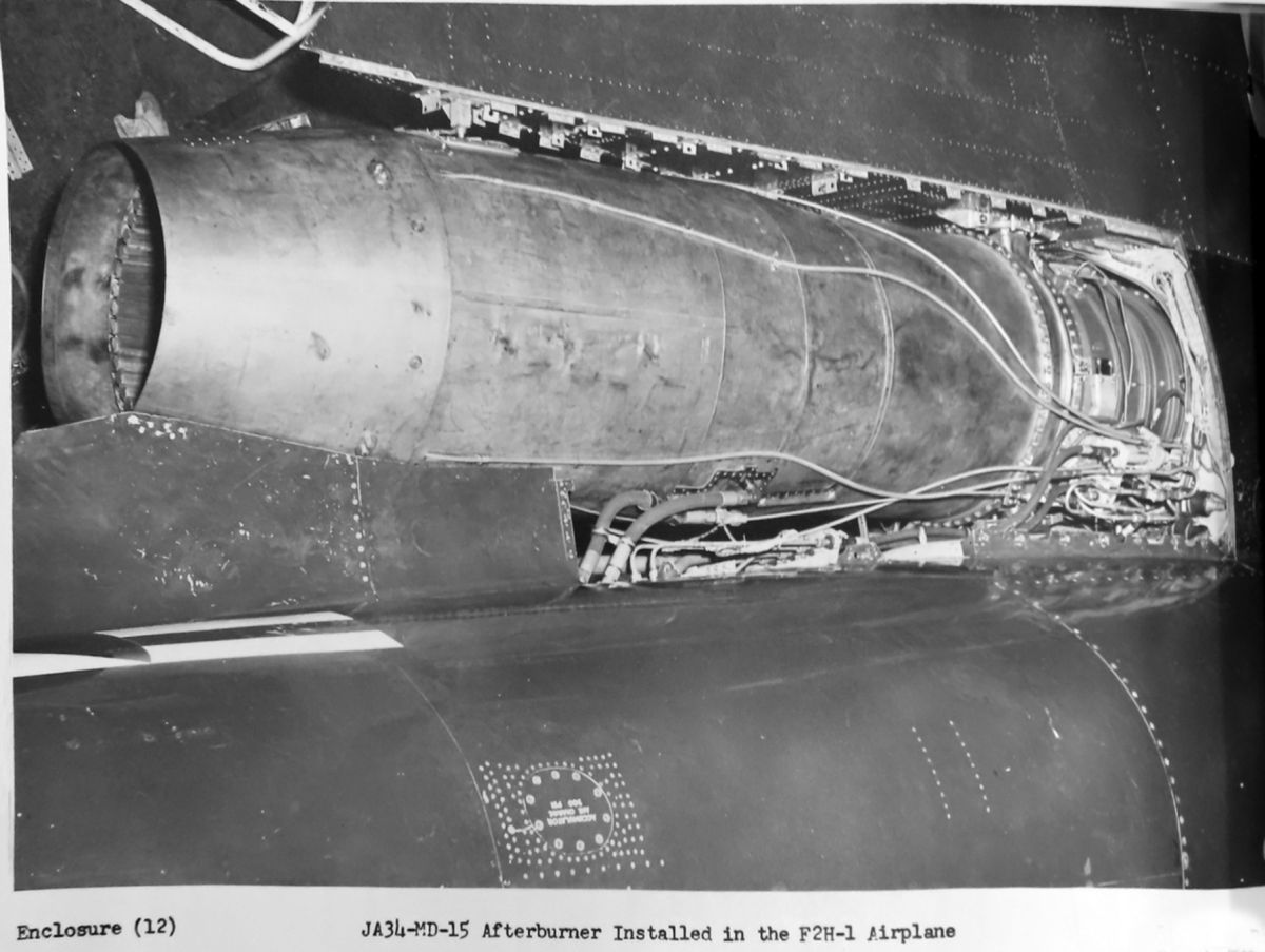
20 October 1950: Results of Flight Test on the Variable‑Area Exhaust Nozzle. Tests were conducted to determine the effect of a variable‑area nozzle on the F2H‑1 and F2H‑2 aircraft altitude performance and endurance. F2H‑1 BuNo 122530 was used with McD short ABs installed. The results were reported in Enclosure 1 (not found). (Note: The Enclosure references are to the numbering of the photographs and charts included with the final McDonnell Summary Report covering the entire McDonnell effort to develop a short afterburner.) The test showed the variable‑area nozzle did not improve the aircraft high‑altitude performance. There was a considerable improvement in the engine controllability. Engine cruise fuel consumption showed a decrease of about 5% at 35,000 ft by use of such a nozzle. A larger decrease could be obtained from an engine without an AB installed. (Italics by author.)
31 October 1950: Contract NOa(s) 9768; Amendment 19, dated 31 May 1950. Additional Afterburner Development Program – Progress Report 6 August to 5 October 1950. Work continued at the Westinghouse Gas Turbine test facilities on investigating expander seal fatigue life, the installation of improved control components in F2H‑1 BuNo 122530 and completion of the JA34‑MD‑17 AB. Static tests investigated the endurance effect on AB efficiency of varying flameholder solidity, fuel‑gas ratio, fuel distribution and the effect of a hot surface in the combustion zone on combustion efficiency and stability.
1. Flameholder heights of 1.125" and 1.250" were investigated in lieu of the ‑16 AB’s 1.0" height. It was concluded efficiency could not be determined unless it was part of an AB into which the increased flameholder had been designed. A 1.125" flameholder step was incorporated into the ‑17 model.
2. Fuel‑gas ratios varying from 0.025 to 0.040 were tested to determine the point beyond which additional fuel produced a negligible increase in thrust. The ratio of 0.035 appeared to be the best. The distribution of fuel varied between the inner and divider flameholders was varied in each of the tests. No one distribution was found to be the best under all conditions. (Ed. – But McD had already done these tests in the air using the XF‑88A and had gotten the same results.) As the fuel cross‑stream penetration had a secondary effect on combustion efficiency, a continuing study of several promising fuel distributions would be made to determine their effect on overall AB operation.
3. Flame stability tests had pointed to the possibility of greatly increased combustion stability and somewhat higher combustion efficiency where a hot surface or wall was in continuous contact with the flame. Some correlation had been found in other McD tests. Testing with two hot surface designs with the normal AB configuration had been done. Although not completely conclusive, a general improvement in flame stability was noted. An unbalanced diffuser flow condition existed in each of the designs and this accounted for somewhat higher internal pressure losses. The JA34‑MD‑17 was constructed to take advantage of the knowledge gained by the tests.
4. Nozzle seal fatigue life tests was conducted. The ‑16 seals gave a life of 75 to 100 hr of engine operation including 5 hr of AB operation on the test apparatus. At room temperature, these seals failed after 8,000 full operation cycles or 1,000 cycles at AB operation temperatures. Testing of materials, including Type 347 stainless (the current design), Type 302, Type N‑155 (for fatigue characteristics) and Hastalloy “B” had shown Hastalloy “B” was the most promising. The tests showed a fatigue life almost five times the best obtained with the current material. Improved seal installation methods contributed to the improvement. Testing would continue to firmly establish the best type and thickness.
5. The improved amplifier and matching thermocouples were installed on one engine of the F2H‑1 BuNo 122530. Initial ground tests showed the control had greater stability and faster response. Flight tests were planned.
6. An improved fuel injection method was under investigation as a possibility for improving AB performance. A design that used compressor air to pump and atomize AB fuel prior to injection into the combustion zones had been constructed and bench tested. Sufficient flow was achieved and a full‑sized injector unit would be constructed and bench tested. It would later be used to explore problems encountered in an actual AB installation.
7. The JA‑34‑17 was fabricated and completed at the end of the reporting period. Installation on a test stand was planned along with a comprehensive test program.
14 November 1950: Memo Confirming Telephone Conversation re: XF‑88 Service Acceptability.(Quoted in its entirety due to relevance to the afterburner development situation at that point.)
“MCREOA‑4‑11‑83‑E Confirming telephone conversation on 14 November 1950 between Major McLauglin, AFDRD‑AV‑1, and Mr. C. L. Hall of the Air Material Command, the following information is forwarded: XF‑88 and XF‑90 airplanes exceed performance requirements of 1945 Military Characteristics and Model Specification guarantees except for radius of action. Radius of action was not met because of following factors: the specific fuel consumption of the J‑34 engines was higher than anticipated by design information from Westinghouse. On XF‑88, external fuel was not carried because proposed production airplane had all internal fuel. The XF‑88 would meet 1945 radius requirements if airplane(s) were flown with external tanks, without afterburners, and if specific fuel consumption is corrected. The XF‑90 was overweight for the power available and excess of fuel was required for all conditions of flight. This contractor stressed the ground support capabilities of the aircraft rather than the escort mission. Weights of versions of YF‑93A are as follows: YF‑93A weight empty – 14,035 pounds, combat weight – 22,977 pounds; take‑off weight ‑ 27,713 pounds; F‑93 with J‑57‑P‑1 engine – weight empty – 20,442, combat weight – 27,418 pounds, take‑off weight – 35,480 pounds. Signed, Engineering Division.”
17 January 1951: Contract NOa(s) 9768; Amendment 19, dated 31 May 1950. Additional Afterburner Development Program – Progress Report 6 October to 5 December 1950.
1. Static JA34‑MD‑17 AB performance tests at McD and Westinghouse, fuel injection and flameholder tests at McD on a JA34‑MD‑16B AB, continued investigation of the variable nozzle expander seals and flight tests of improved control components were performed during the period. A total of 29.5 hr of all‑condition AB testing was accomplished of which 2.1 hr of engine‑AB operation time was run at Westinghouse, 1.7 hr at the McD static test facilities and 0.20 hr in McD flight tests with the F2D‑1 BuNo 122530.
a. Operational ‑17 AB tests were conducted to determine thrust losses, operating characteristics, and the design structural integrity.
b. Engine thrust losses were measured at between 1 – 2% of engine thrust with standard tail pipe. The result was in agreement with theoretical design analysis.
c. Successful ignition with the hot streak ignitor and full open exit nozzle was obtained at 40% of maximum AB fuel flow.
d. The new light weight design feasibility appeared to be borne out by the above results, including:
i. The semi‑cantilevering mounting with bob‑weight supports was completely satisfactory, proving completely stable with no damping being used.
ii. The moveable shroud resulted in much smoother nozzle area changes.
iii. Even with the hydraulic actuators for the shroud being mounted close to the AB skin, the asbestos insulation and radiation shielding proved adequate in maintaining a permissible operating temperature.
iv. The fuel tube radial position variation exposed a region of high vibration and noise level. No operation in the resonating zone produced any performance improvement and no further testing was done in that zone. However, fatigue cracks were found at the end of testing around the combustor at the junction of the center cone and supporting struts. As a result, the rigid junction was replaced with a floating construction in which telescoping struts were used.
2. At Westinghouse, special tests were run regarding variations in performance caused by different fuel tube positions. Approximate 9 hrs of engine time, which included 2 hrs of AB operation were accumulated. It proved the performance could be measurably changed by the positioning of the fuel injectors. The cleaner internal design appeared to result in greater stratification of the fuel distribution. This resulted in a lower overall AB temperature rise and indicated a different injection method would be necessary for the ‑17 design.
a. Further structural failures occurred during the Westinghouse tests. Difficulty was experienced with the center cone section aft of the flameholders.
b. The N155 stainless steel had lost 25% of its original thickness due to scaling in the 2,000°F temperature at that location, the part collapsing inward. Type 310 stainless was substituted and the testing continued.
c. Part of the radiation shield made of 0.010" type 347 stainless steel failed from “oil canning” fatigue induced by actuating stresses through the shroud and radiation shield. The part was modified to remove these actuation stresses on the thin section of the radiation shield. One further failure occurred in the nozzle expander seals at the end of the test period.
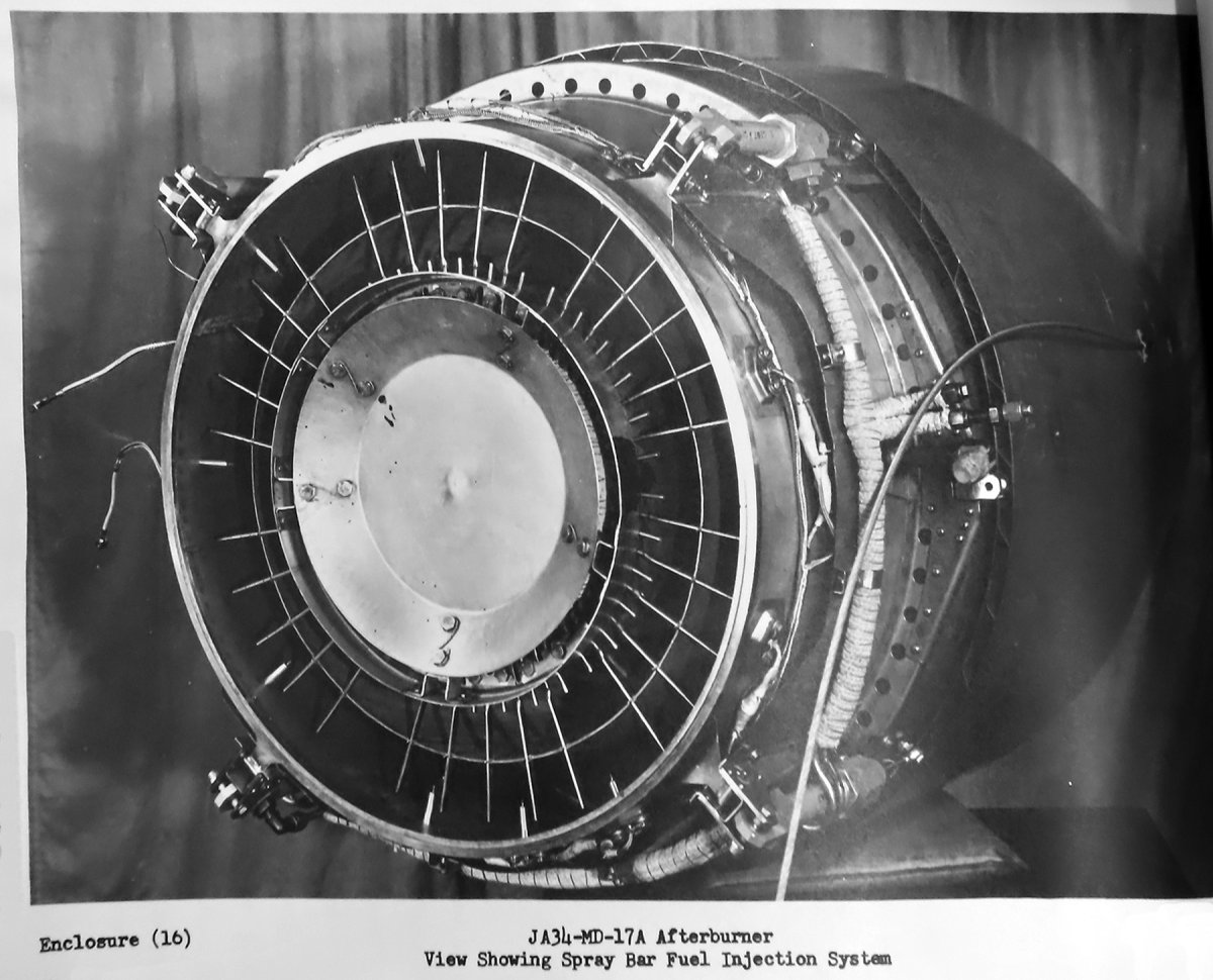
3. To obtain a more uniform fuel distribution, a few tests were run using a ‑16B AB to determine the suitability of using a spray bar injection. Early results indicated improvement. A 25% improvement in overall efficiency over that of the finger type injection appeared was noted. In addition, operational vibration and noise level appeared to be reduced in spite of the improved performance. The spray bars were being installed in the ‑17 and would be tested during the next reporting period.
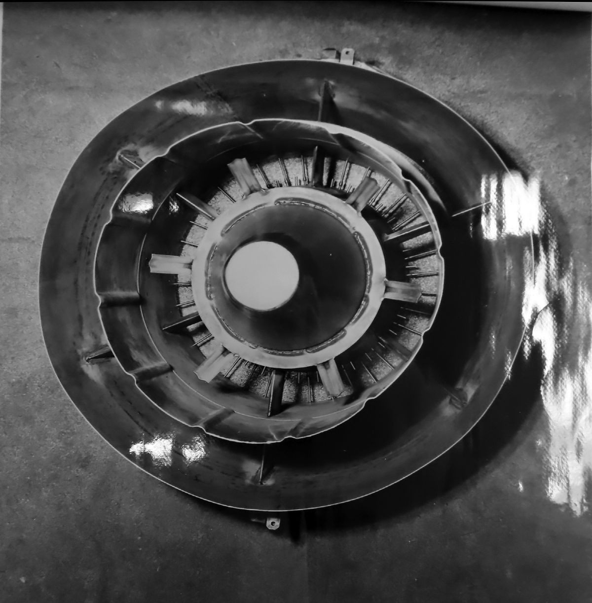
4. A parallel investigation of possible performance improvement was conducted using short radial flameholders on the inner ‑16B flameholder. Six 1.0" wide, “hat” section flameholders approximately 3" long were welded with a 45° sweep‑back. An approximate 10% performance improvement was noted. No increase in AB cold loss was apparent during the tests, but theoretical analysis indicated additional thrust losses would be about 0.10%.
5. Hastalloy B alloy seal testing experienced several seal failures after approximately 3 hrs of AB operation under severe conditions. The failures were due to metal erosion rather than the previously experienced fatigue failure. Analysis showed the Hastalloy B did not have sufficient corrosion resistance for the maximum temperatures encountered in nozzle hot spots. Additional tests using Haynes Stellite alloy L605 were conducted. This alloy gave better fatigue life than Hastalloy B and was corrosion resistant to 2,200°F compared to Hastalloy B’s 1,600°F. The L605 would be used to repair the ‑17 burner and construct other test burners of that design.
6. The jet pump fuel injection full scale pump was fabricated and tested. Assembly into the ‑16B AB was underway.
7. The improved control components were flight tested. Two sensitivity settings were tested in level flight at altitudes of 10,000, 20,000 and 30,000 ft and in a climb from 25,000 to 35,000 ft. The response rate and the TOT variations were considerably improved.
15 March 1951: Contract NOa(s) 9768; Amendment 19, dated 31 May 1950. Additional Afterburner Development Program ‑ Progress Report 5 December 1950 to 5 February 1951. Static performance tests of the ‑17 AB on the McD thrust stand, installation of the jet injector pump in a ‑16B AB, installation of a ‑17A AB in the BuNo 122530 and continued examination of the variable nozzle expander seals were conducted. The total all‑condition static AB time of 13.1 hr was accumulated of which 3.4 hr were engine‑AB operation.
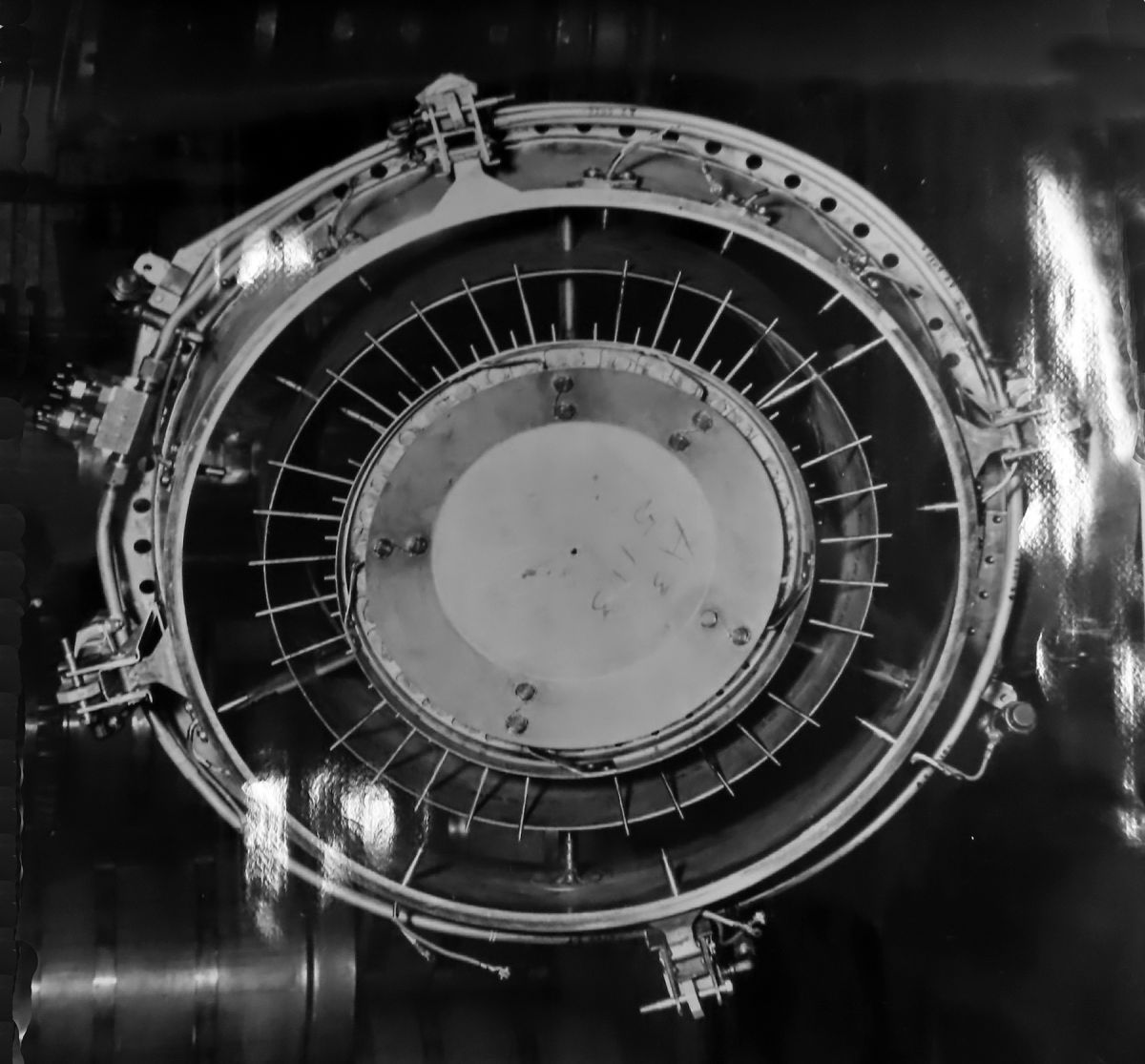
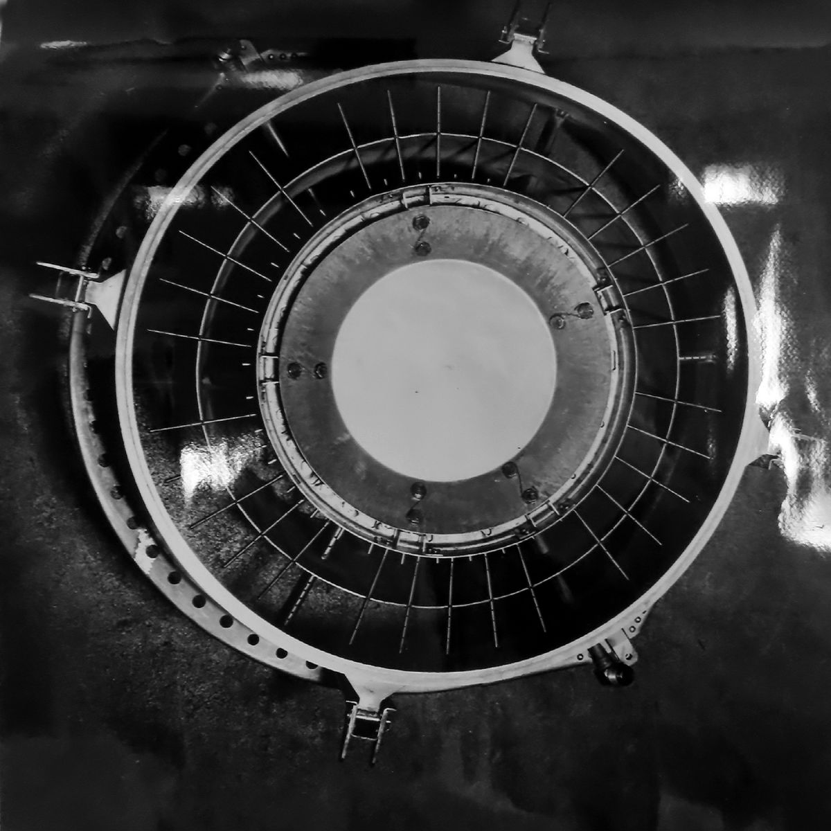
1. The ‑17 AB tested originally used finger type injection that injected fuel at two radial positions with respect to the AB center line. (See Fig. 4.) Those two positions were slightly outboard of the center cone step and divider.
Fig. 4. Initial JA34‑MD‑17 Finger Type Fuel Injection Design
Fig. 5. Alternate ‑17 Design with Modified Injection Tube Positions
Fig. 6. Short Radial Flameholders Tested on the ‑17
Another arrangement using a spray bar was investigated. With this, the injection holes were in the tube leading edges extending out from the center cone. Each tube served as a manifold to inject fuel in the gas stream at three positions between the center cone and divider and at four positions outboard of the divider.
2. The minimum fuel flow required for ignition with the spray bar design was higher than that required for ignition with the finger type design. This was a result of the more uniform fuel distribution in the new design, whereas the finger type injection created a greater concentration of the total fuel flow in the flameholder region, which permitted ignition at a lower fuel flow value . The finger type provided for ignition at 40% of the maximum AB fuel flow versus the spray bar’s requirement of 55 to 60%. Short fuel tubes projecting from the center cone were added to supply fuel only for ignition and it was planned they would be removed if ignition at low fuel levels proved unnecessary.
3. The spray bar design provided for fuel injection at several radial positions and had a higher efficiency than the finger type. The tests indicated that with the change from the finger type to spray bar type the efficiency increased by approximately 10%.
4. Short radial flameholders attached to the inner cone were tested in conjunction with the pattern provided by the spray bar injection and these were found to increase efficiency by an additional 4%.
5. Typical AB efficiency curves obtained with both the spray bar type injection and finger type injection were plotted. (Enclosure showing curves was not found.) The ‑17 AB with spray bar injection and radial flameholders exceeded the specified performance.
6. The jet pump fuel injector installed on the ‑16B AB No. 9 was completed. It used compressor bleed air as the primary fluid in an ejector designed to pump the AB fuel. It was expected to pump at high velocity a mixture of air and fuel in a finely atomized and partially pre‑heated condition. The compressor bleed air was fed back into the engine, the amount approximately equal to the present turbine type AB fuel pump. The AB would be installed on the McD test stand the next reporting period.
7. Installation of a ‑17A AB in BuNo 122530 was initiated. Improvements from testing the initial ‑17 noted above were included in the ‑17A.
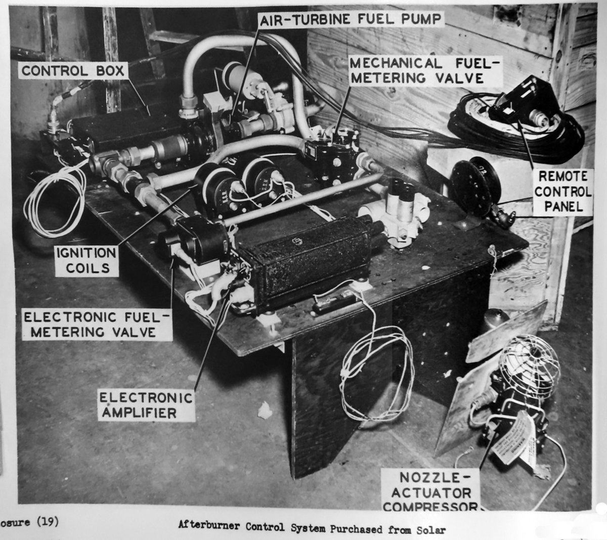
8. An AB and engine control meeting the specifications was installed in BuNo 122530 and would be tested with the ‑17A. A single power lever was used in the control system for both engine and AB. It coordinated the variable area nozzle, acceleration, and rpm for engine operation and controlled the AB operation from minimum fuel flow for ignition to maximum power fuel flow. Emergency nozzle operation during either engine or AB operation were provided in the event of electronic control malfunction.
9. Nozzle expander seals fabricated from Illium (a Nickel based alloy) were cycle‑tested at elevated temperatures as part of the materials selection program, still underway. The tests showed the Illium was inferior to L‑605 material tested previously.
7 May 1951: A general engine model restriction on using more than 96% rpm above 30,000 ft for the J34‑WE‑34 engines in the BuNos 123204, 123311, and 122530 was lifted. This was done to allow continued AB testing. The restriction had been placed because the J34‑WE‑34 engines had a temperature inversion problem that affected the turbine blades and blade rubs were occurring in some engines. New mixers were being retrofitted to existing engines to eliminate the problem. McD was instructed to keep the rpm time above 96% to a minimum on the three engines.
14 May 1951: Contract NOa(s) 9768; Amendment 19, dated 31 May 1950. Additional Afterburner Development Program ‑ Progress Report 6 February 1951 to 5 April 1951.(Note: None of the photographs included in the report were found.) At the end of the testing covered in this period, a total of 41.06 hrs of all‑condition and 4.97 hrs AB operating time was accumulated. Of those totals, 17.44 hrs all‑condition and 0.80 hrs AB operation was flight time.
1. The ‑17A AB was tested for 10 hrs using alternating 5 minute periods of AB wet operation and idle dry. Total thrust was 4,510 lb based on a basic 3,410 lb engine thrust on a standard day. Augmentation was 32%.
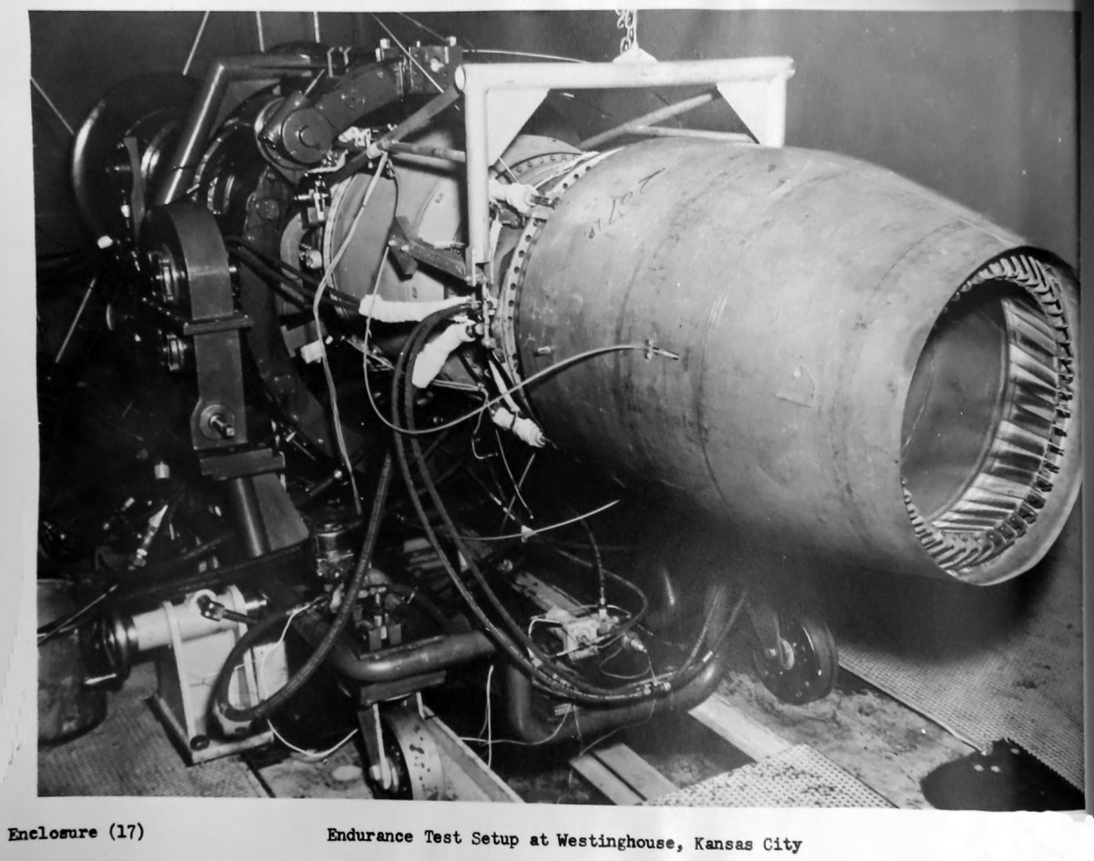
a. The No. 108 burner was tested for endurance at Westinghouse in Kansas City after a preliminary operating check was completed on the McD test stand. After two hours of AB operation a small hole was found in the center cone downstream of the flameholder. This appeared to be caused by oxide scaling reducing the metal thickness. It was constructed of a Haynes Stellite alloy known as L‑605. Testing showed that each time the AB temperature cycle was completed a new layer of scale was formed and the metal thickness reduced by 0.001".
b. The center cone aft section was replaced by one made from Z10 stainless steel with six stiffening beads and testing was continued. The beads were added to prevent the collapsing of the center cone as had been previously experienced with this material. However, some collapsing was found after 0.5 hr of continued testing. The radial flameholders were then reduced in width at the flameholder root in an attempt to cool the metal. No cooling was evidenced and after 1.75 hrs a hole burned through the material downstream of the flameholder.
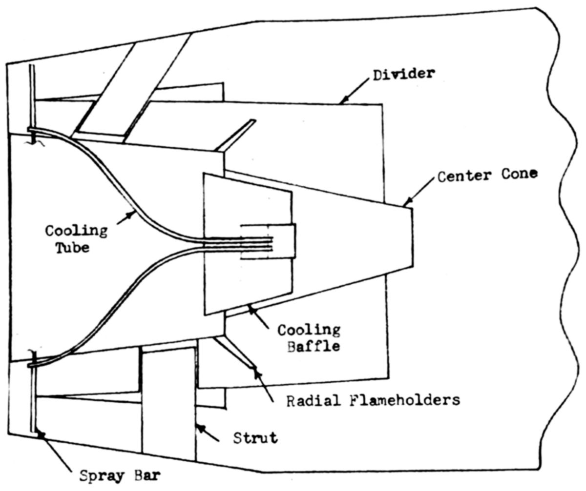
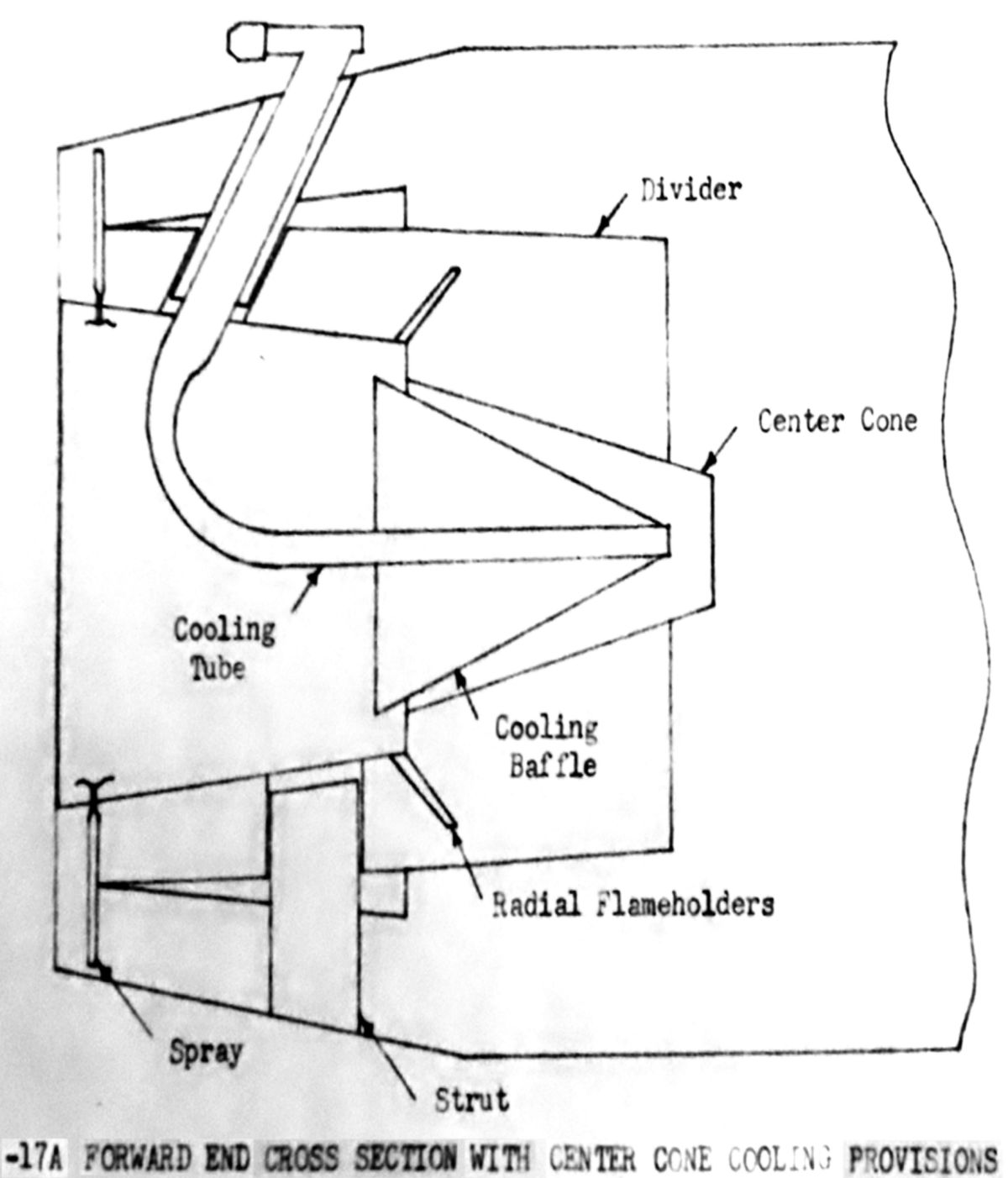
c. A new center cone was under construction with provisions added for cooling the portion down steam of the flameholder. This would be accomplished by using turbine gas picked up by tubes at the center cone leading edge and carried back to the cone downsteam end. The gas would then move forward through a passage designed to direct cooling air inside the center cone material. This design would be tested at Westinghouse Kansas City.
d. The AB performance exceeded the specification and had an SFC of 2.36 lb/hr/lb at standard sea level operation. The test engine was one used for experimental purposes only and whose performance was below the current production average.
e. The ‑17A No. 103 AB nozzle had several regions that operated at high temperature during the tests. The circumferential temperature distribution was not satisfactory although the radial temperature distribution was within limits. Later testing was done with the nozzle rotated 90°. This showed the turbine outlet temperature (TOT) distribution was a factor in the nozzle distribution, but the nozzle itself was also contributing to the hot spots. Some success was achieved by changing the AB fuel distribution in hot spot areas.
f. The No. 103 nozzle was constructed using investment‑cast (lost‑wax) nozzle segments. The segments were functionally satisfactory during the endurance testing.
2. Flight tests on the JA34‑MD‑17A AB and JC34‑MD‑3 control were conducted during the period. Reduction of rpm at 30,000 ft and above was required, so no testing at that altitude or higher was done as the corresponding drop in TOT temperature made the comparison of performance with that at below 20,000 ft impractical.
a. The JC34‑MD‑3 control had some difficulties. Minor modification was required to provide proper scheduling and adjustment before flight testing was possible. During flight, oscillation in the TOT was experienced and some correlations between these oscillations and the acceleration loads on the aircraft were found. Further modifications would be made to the control and flight testing continued.
b. Successful ignitions were obtained up to 30,000 ft at reduced fuel flow at maximum power. This indicated AB performance would be satisfactory at or above that altitude if reductions in engine rpm were not required.
c. Bob weights used in the ‑17A AB were found to exceed the space limitations if limit loads were applied to the airplane. New weights and supports were designed constructed for installation.
3. The ‑16B AB, No. 9, with the jet pump fuel injector installed was operated on the McD test stand. AB operation was unstable at first because the flame failed to seat on the flameholder. Changing the point of fuel injection caused the flame to seat but combustion was considered to be too rough for long periods of operation. During short periods, however, the operation appeared to be satisfactory. More adjustments in the fuel/air injection points would be made and static test stand testing continued.
4. Additional cycle tests on nozzle expander seals of L‑605 material were conducted using several thicknesses. Seals of 0.015" thick proved to be superior in those tests.
5. The center cone and strut structure of the ‑17 AB No. 101 was loaded statically and found to be more than adequate structurally. Loads of 40% greater than design on the center line of thrust and one of 105% greater than the design limit were applied normal to the center line of thrust. No failures occurred.
12 May 1951: Contract NOa(s) 9768; Additional Afterburner Development Program ‑ Progress Report 6 April 1951 to 5 June 1951. At the end of the testing covered in this period, a total of 50.96 hrs all‑condition and 6.99 hrs AB operating time was accumulated. Of those totals, 44.18 hrs of all‑condition and 4.99 hrs AB operation was flight time.
1. Static performance tests were performed on the JA34‑MD‑17A, No. 103 AB. At McD, the center cone, which had failed during the static tests at Westinghouse, Kansas City, was replaced by one designed to use turbine discharge gas to cool the center cone material. In test, the new cone had a temperature drop from the cooling gas flow of 100°F at the center cone aft end, but the drop decreased toward the flame holder.
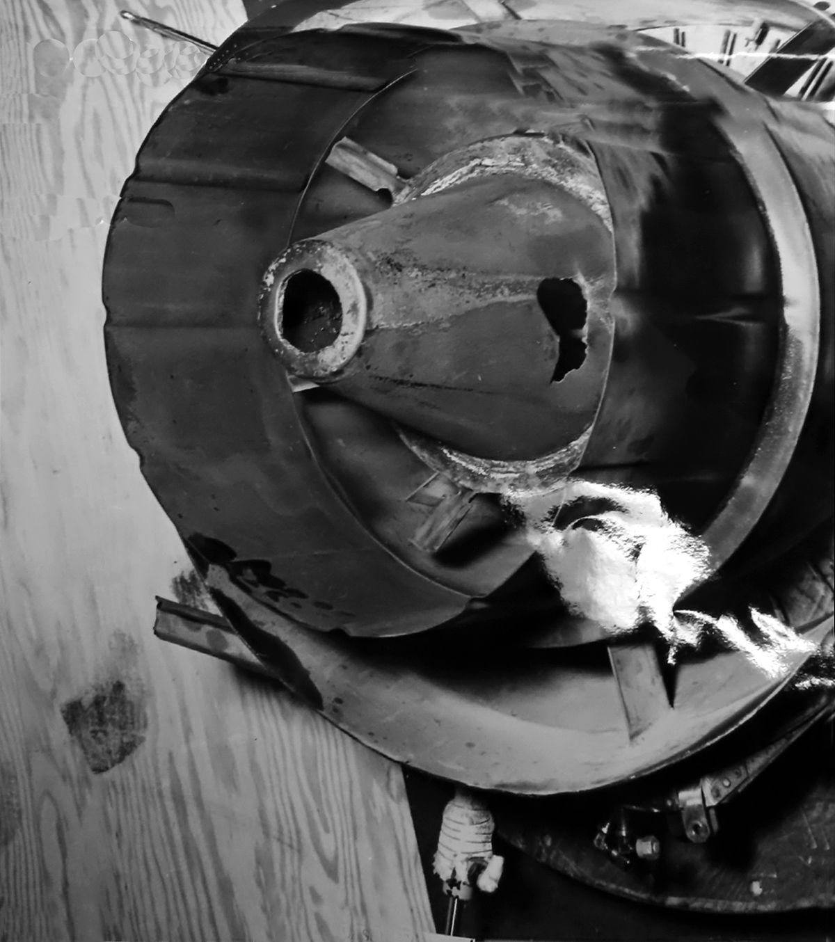
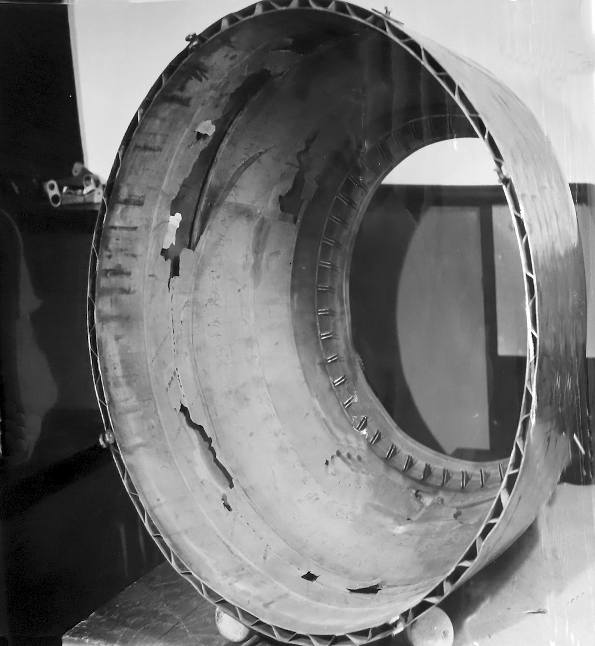
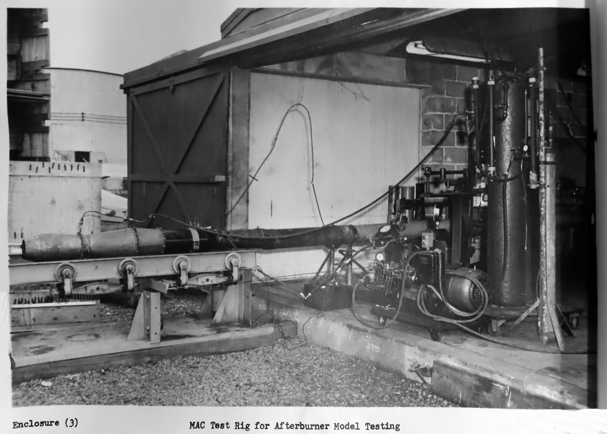
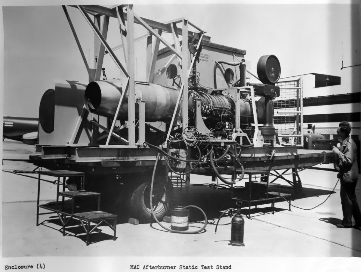
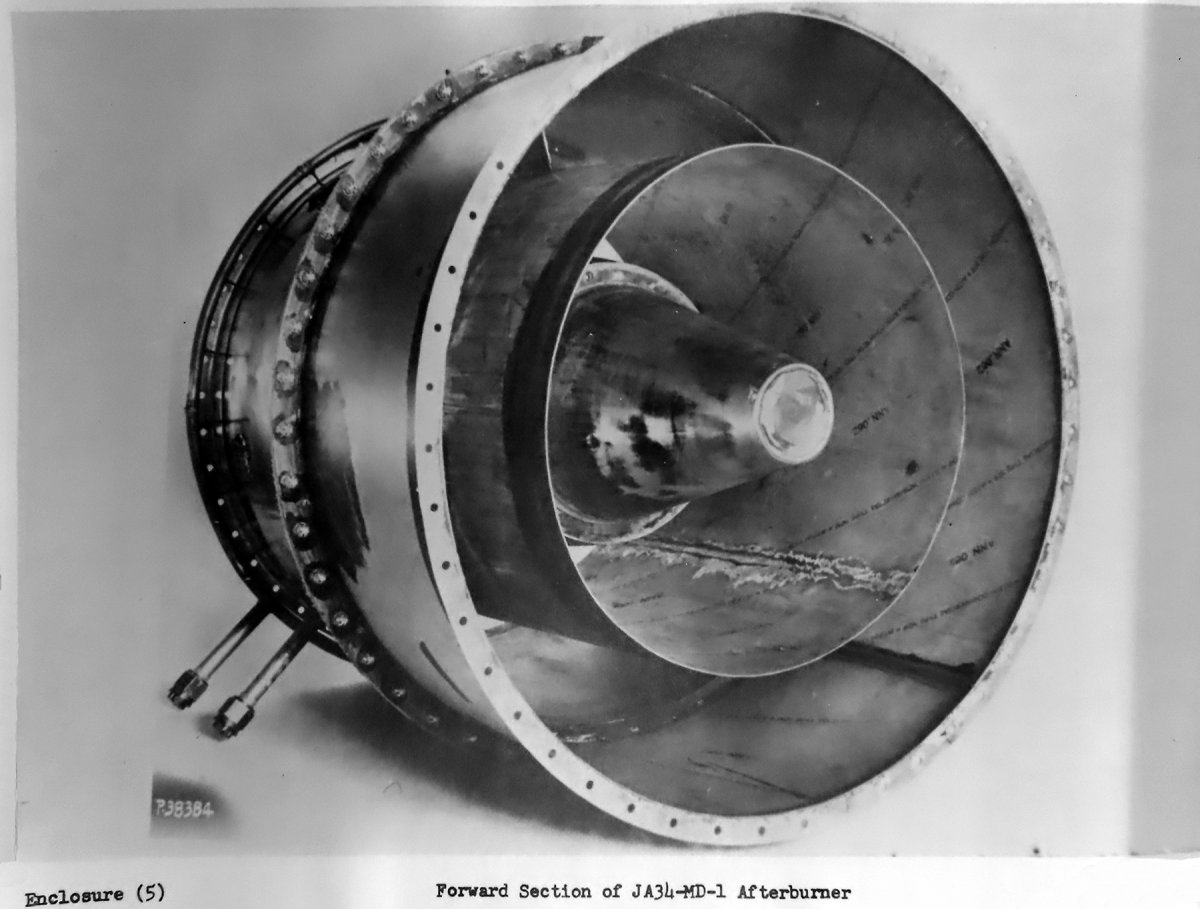
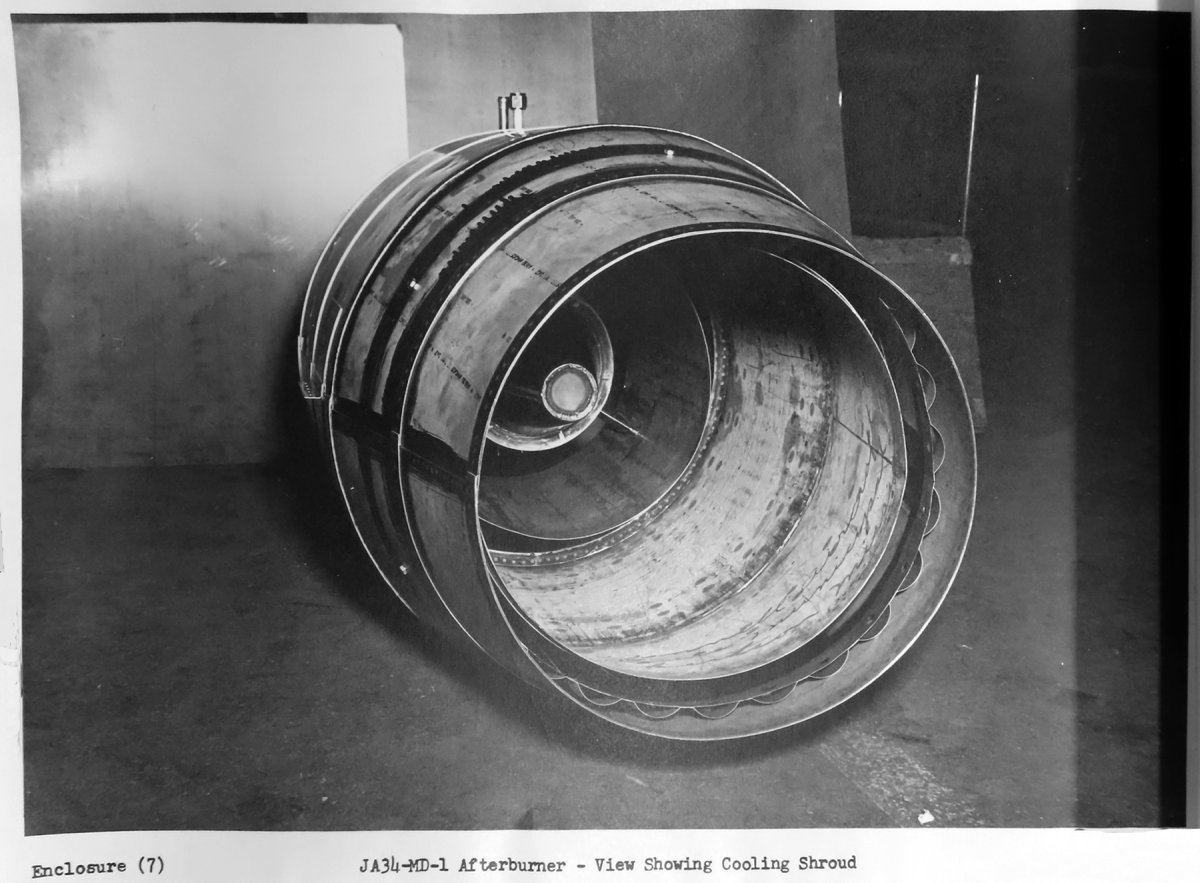
2. The No. 103 burner was tested at Kansas City. Endurance testing consisting of 10 hrs of alternate 5‑min periods of wet operation and 5‑min periods of idle operation at a performance level while AB wet equivalent to 4,510 lb static thrust on a Standard Day at sea level if the engine alone would produce 3,420 lb thrust under the same conditions. The new center cone failed after 19.5 minutes of AB operation. No other failures occurred during the tests. In the Figure 8 image, two holes are visible in the cone, but the damage inside the cone is not visible. No buckling (a common occurrence in prior earlier cone testing) was found in this instance. It was believed the cooling tubes picked up sufficient fuel from the spray bars to form a combustible mixture inside the center cone and the resulting combustion caused the failure.
3. The No. 103 AB was reworked again to incorporate the center cone and cooling medium shown in Figure 9. This cooling system used compressor bleed air brought into the center cone via a strut. The radial flameholders were also removed with the expectation this would lower the center cone temperature materially, but this did not occur. Limited temperature control was achieved by varying the amount of fuel injected near the center cone. The most practical solution seemed to be the use of compressor bleed air for center cone cooling, as an air flow of 0.123 lb/sec (0.22% of the engine flow), reduced the temperature of the material to a safe operating level. The radial flameholders would be replaced and if the center cone temperature and AB performance remained satisfactory, the AB would be returned to Westinghouse for further endurance tests.
4. Flight tests were conducted on the ‑17A and JC34‑MD‑3 control with the testing primarily directed toward adjustment and evaluation of the AB control system. Some qualitative AB performance was obtained during the tests.
a. The ‑17A AB had been operated from sea level to 45,000 ft. Over‑speeding of the engine at higher altitudes precluded testing at anything higher, but it appeared that it was possible to operate at higher altitudes. Ignition had been obtained at 43,000 ft and Mach 0.75. Stable combustion at redline temperature was maintained over the complete operation range.
b. The bob weights and supports used in the airplane installation were replaced with newly designed ones to reduce the bob weight arm deflection during acceleration loads. Completely satisfactory performance was obtained.
5. The ‑16B AB was operated with the jet fuel injector pump installed on the McD thrust stand. Initial short rough combustion periods precluded data collection, but adjustments to the point of fuel injection reduced the roughness to the point where data collection could then occur. Performance was above that of the ‑16B but less than the level that was expected from the short periods of operation. It indicated that in obtaining a mixture rich enough at the flameholder to support stable combustion, the advantages expected from the uniform fuel distribution possible with the jet pump were eliminated. The unit's fuel distribution tubes would have to be replaced by tubes designed to supply the flameholder with sufficient fuel for stable combustion and also provide the uniform distribution possible with the jet pump before a proper fuel injection method evaluation could be made.
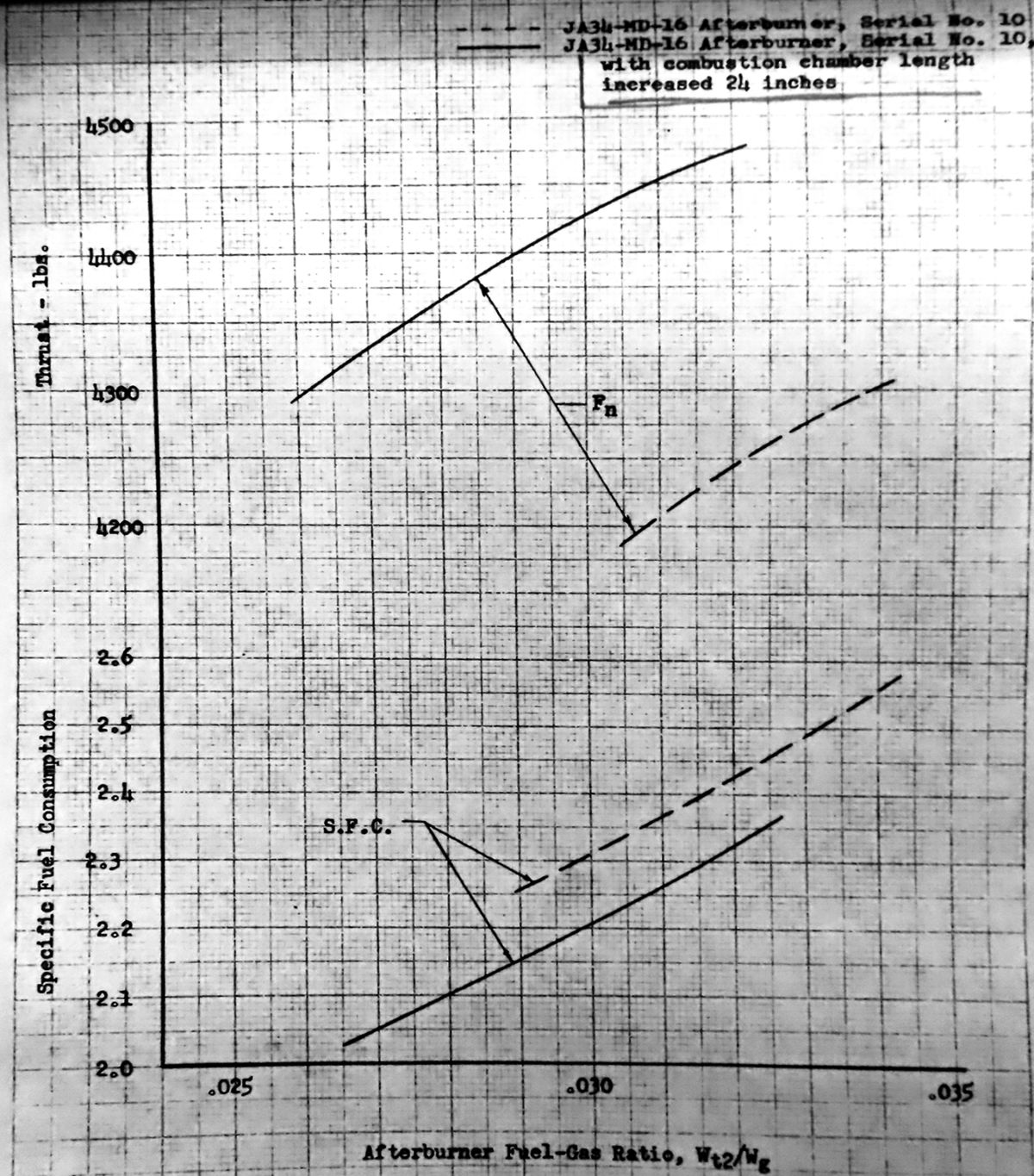
6. To test the effect of combustion chamber length, the ‑16 No. 10 AB was altered to increase the combustion chamber length to 24". This was then tested and compared to the short length chamber’s performance. For the results, corrected to 12,500 rpm and 1,490°F turbine in temperature, see Figure. 10.
a. The length increase had increased thrust by 250 lb and reduced the SFC by 10%. Theoretically, it would also increase the non‑burning thrust loss.
b. The longer combustion chamber design performance was being equaled or surpassed by the ‑17A then in test. A long combustion chamber version of the ‑17A was expected to increase the performance attainable with the McD AB.
Fig. 7. JA34‑MD‑17A AB Forward Cross Section Showing the New Center Cone Cooling Provisions
Fig. 8. Damage to the Center Cone after 19.5 minutes of Testing
Fig. 9. JA34‑MD‑17A Forward End Cross Section with Provisions for Center Cone Cooling
Fig. 10. Performance Data of Short and Long ‑16 AB Combustion Chambers
13 October 1951: Contract NOa(s) 9768; Additional Afterburner Development Program ‑ Progress Report 6 June 1951 to 5 August 1951. Development work during this period included the endurance testing of JA34‑MD‑17A, No. 103, AB at McD and Westinghouse, preliminary tests on a JA34‑MD‑17A AV with extended combustion length, acceptance test of F2H‑2N BuNo. 123311 equipped with ABs, and flight tests of BuNo. 122530 with ABs. At the end of the testing covered in this period, a total of 42.85 hrs of all‑condition and 17.61 hrs AB operating time had been accumulated.
1. An endurance test of No. 103 AB was satisfactorily carried out at Westinghouse, Kansas City from July 10 – 21 July. All‑condition time accumulated was 25.9 hrs. The AB was operated wet for 13.27 hrs at an augmentation of approximately 31.2% without a failure that would prevent the AB from completing the additional all‑condition time required by the specification.
a. Prior to the start, the center cone air‑cooling was tested on the McD test stand. The tests showed the method was a satisfactory solution to the center cone overheating experienced in earlier testing. The six radial flameholders were reinstalled.
b. Calibrations of the engine with the standard tailpipe and with AB installed were done before the test.
Pre‑test Calibrations Results*
Tail Pipe
CorrectedThrust (lb)
Engine RPM
OverallSFC (lb/hr/lb)
Turbine Inlet Temperature
Standard Tailpipe
3,200
12,500 (Military)
1.066
1,437°F
Afterburner Dry
3,155
12,500 (Military)
1.086
1,433°F
Afterburner Wet
4,290 (34%)
12,500 (Military)
2.52
1,492°F
*The test engine was below the guaranteed rated thrust of 3,250 lb and SFC of 1.06
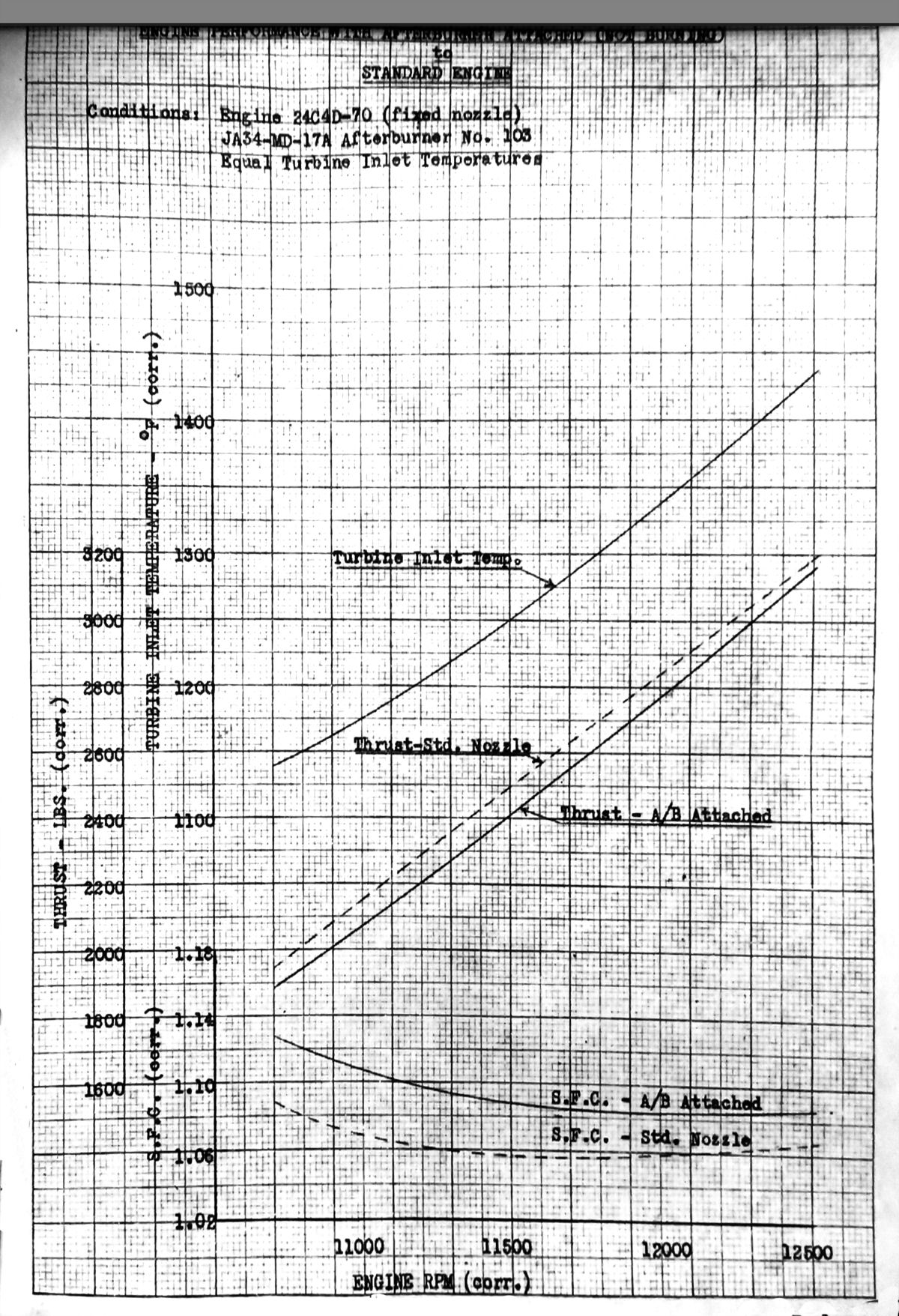
c. A comparison chart of the engine with the AB installed shows a thrust loss of 1.12% and an SFC increase of 1.89% at Military rpm.
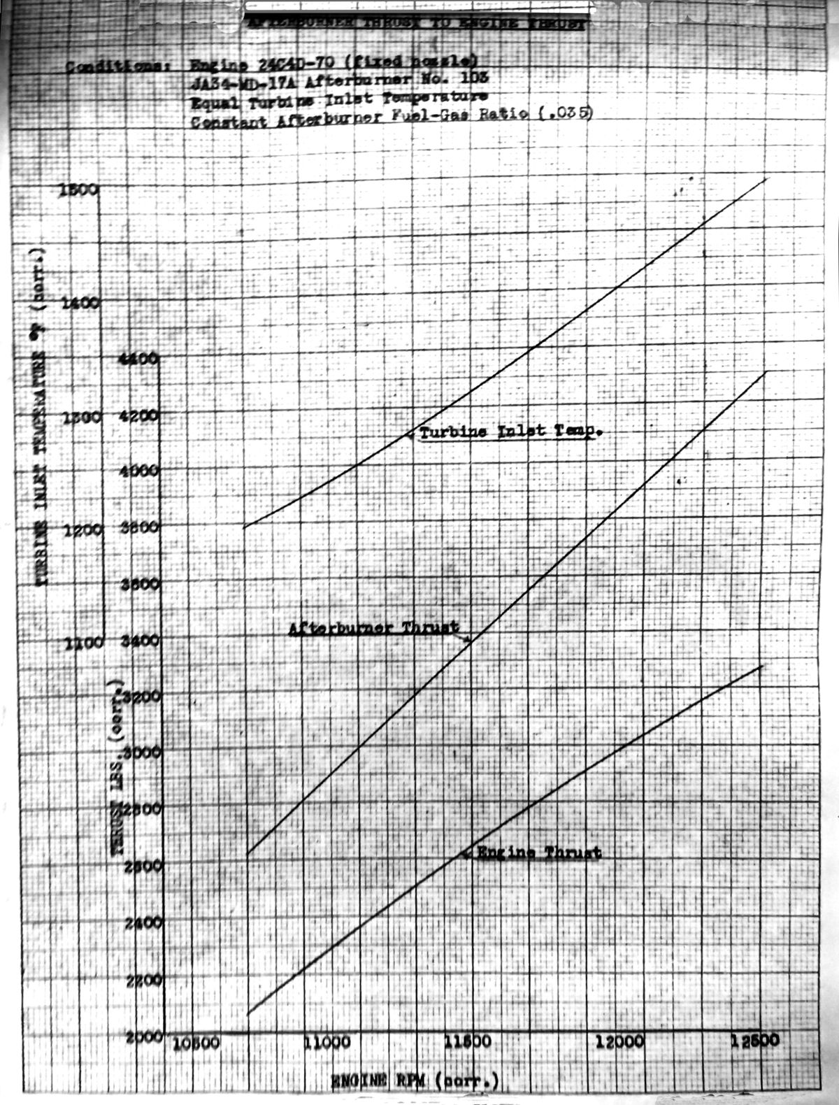
d. A comparison chart of thrust increase for the AB at 0.035 AB fuel/gas ratio compared to the standard engine at Military rpm shows a thrust of 4,290 lb or 31.2% augmentation.
e. The endurance tests were conducted at a 0.035 AB fuel/air ratio and at the start were five minutes of AB wet at 12,500 rpm and five minutes idle. After five hours of accumulated AB time, the AB period was extended to fifteen minutes. This was to allow more AB hours in the same length of test time.
f. The tests were unavoidably interrupted because of a river flood condition from 13–19 July. An accumulation of 25.9 hrs of all‑condition time and 13.27 hrs of AB time was obtained without AB maintenance, except for minor fuel distribution alteration in an unsuccessful attempt to cool hot spots on the nozzle. The tests were again stopped due to a general fuel shortage at the site.
g. The AB, at that point, had 46.44 hrs all condition and 21.69 hrs of AB time, including the endurance testing. Only the center cone (3 times), the radial flameholders and 4 nozzle segments had to be replaced. The latter before the endurance testing started.
h. Minor failures during endurance testing were cracks in the flow divider and breaks in the radiation shield 2nd and 4th sections. The longest of the flow divider cracks was 7" long at the end of the test. The radiation shield components at that point were made of lighter material than the other two sections. Two small cracks in a nozzle segment did not progress during the test. Some small cracks in the AB shroud fairing were also found.
2. Further evaluation of the 24" long combustion length using the ‑17A was done. It utilized spray bar fuel injection. The tests were run without an ejector shroud and with a fixed conical exit nozzle.
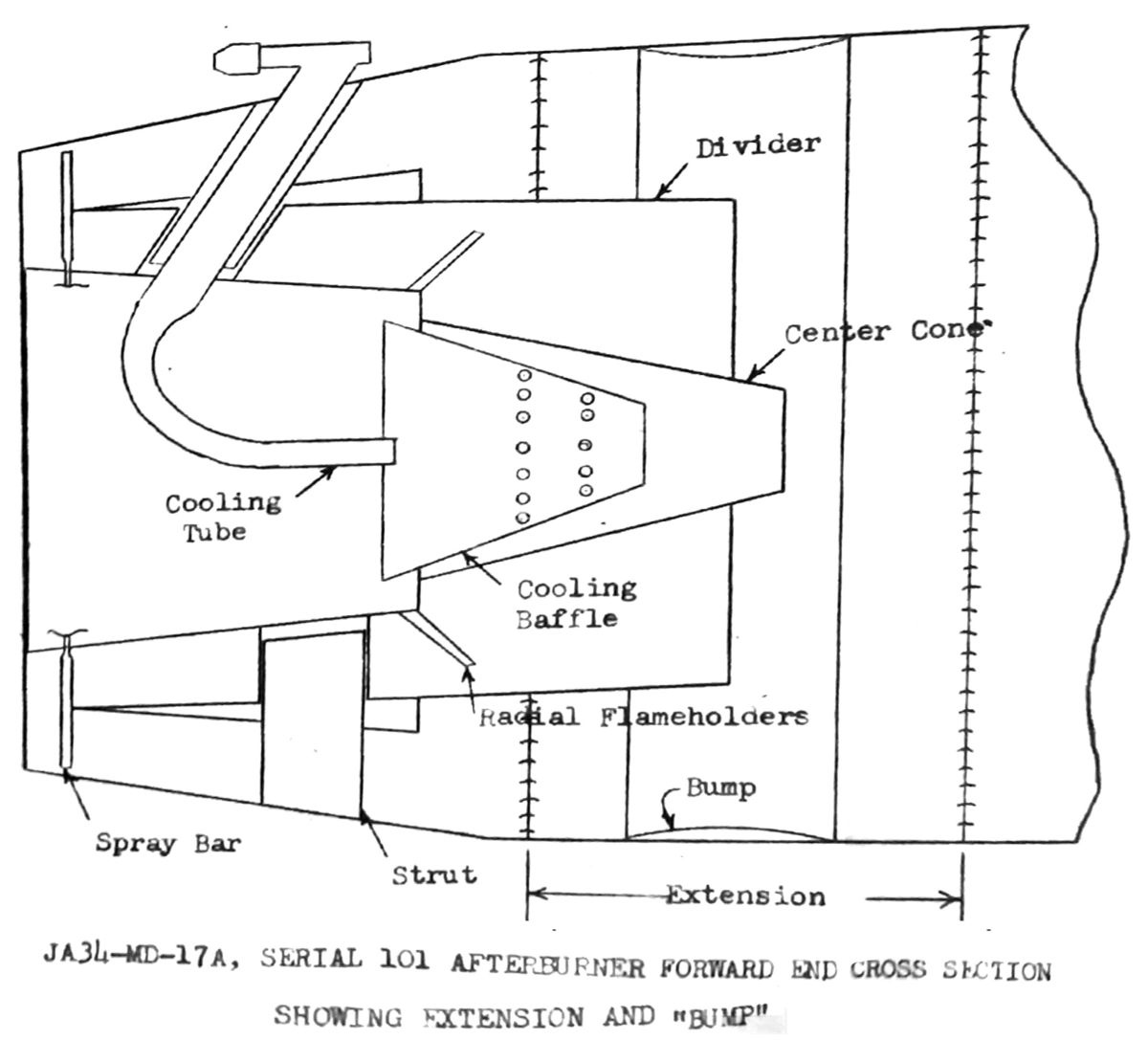
a. Of concern was the high frequency “squeal” when operating above 5,500 to 6,000 lb/hr of AB fuel. The shortening of the length by 12" and modification of the fuel injectors to increase the fuel percentage to the inner flameholder only slightly improved the condition. The addition of a “bump” on the combustion section outer wall to improve the flow balance through the diffuser and especially around the diffuser divider leading edge did not materially change the performance or eliminate the “squeal”.
b. While an increase in AB efficiency at the level tested was observed, due to the destructive qualities of the squeal, insufficient data was obtained to make a complete evaluation of the modified No. 101 AB.
3. In preparation for delivery of F2H‑2N BuNo. 123311 to Patuxent for tactical evaluation, two check‑out flights were made to 35,000 ft with JA34‑MD‑16 ABs No. 17 and 18 installed. Performance was satisfactory. Flights on F2D‑1 BuNo. 122530 with JA34‑MD‑16B AB No. 7 and JA34‑MD‑17A AB No. 102 installed made flights on 7, 13, and 15 June 1951 to test the stability of the Manning, Maxwell & Moore temperature control and the AB blowout altitude. The stability was satisfactory. Blowout of the ‑16B occurred at 46,000 ft. The ‑17A blew out at 51,200 ft when the pilot alleviated a compressor stall by using momentary openings of the variable nozzle to maximum area. Altitude ignition limits of the ‑17A remained unchanged at 43,000 ft.
4. Future work would continue on the ABs with extended combustion length, including a series of tests on the ‑16B AB with finger fuel injection to continue the investigation of the effect of fuel distribution on squeal characteristics. Construction would also be started on three JA34‑MD‑17 ABs and three JC34‑MD‑3 control systems for flight testing on BuNo. 122530. The airplane would be overhauled and repaired as necessary for further flight testing.
Fig. 11. Engine Performance with AB Attached but not Burning
Fig. 12. AB Thrust Augmentation Relative to Engine Thrust
Fig. 13. JA34‑MD‑17A Radiation Shield After Endurance Test
8 November 1951: Contract NOa(s) 9768; Additional Afterburner Development Program ‑ Progress Report 6 August to 5 October 1951.
1. General – Progress made by the McDonnell Aircraft Corporation from 6 August through 5 October 1951 in the AB development program, authorized under the subject contract, is reported in the following paragraphs.
a. The primary objective of the subject program was the status and flight test development of the McD short AB and controls directed toward acceptance testing of the AB for service airplane use in accordance with the AB specification.
b. The program’s secondary objective, according to the 27 November 1950 “Proposal for Further Development of Afterburner” was modification and refinement, if desirable, of various parts of the AB directed toward improving the overall AB performance. Therefore, during the current report period, McD continued to explore the potentialities of the ABs.
2. Activities of This Report Period – Since no immediate activities were scheduled for the short AB after its acceptance test run, the AB development work conducted was devoted to the investigation of the effect of combustion length on JA34‑MD‑16B and ‑17A ABs. A time of 5.1 hrs all‑condition time and 1.2 hrs of AB wet time was accomplished on a McD test stand.
a. The ‑17A AB No. 101 had a 24" combustion chamber installed just after the diffuser section in lieu of its normal 12" section. The variable nozzle and shroud were replaced with a fixed nozzle and the center cone was provided with compressor airbleed cooling. The AB had spray bar fuel injection and six radial flameholders attached to the center cone. After a few runs, the length was reduced back to 12".
b. The first tests with the extended length combustion chamber experienced squeal. With a fuel flow above 5,000 lb/hr and higher, squeal occurred and intensified. The destructive nature of the squeal was evidenced by the TOT thermocouples being broken up and their pads broken loose from the AB after a short AB run. This had not been encountered earlier with the short AB with a spray bar or with long AB Serial No. 10’s finger‑type injection. It was assumed to be inherent in the combination of the longer length and the more uniform fuel distribution of the spray bar fuel injection.
c. An aerodynamic bump on the combustion section outer wall opposite the flow divider trailing edge (See Fig. 14) was installed in an attempt to improve the balance of flow through the gas diffuser. With this installed, squeal was encountered at a slightly lower AB fuel/air ratio. After shortening the combustion chamber again and increasing the fuel to the center cone, a small improvement in squeal reduction was noted. After the bump(s) were removed, a data point at 6,000 lb/hr of fuel was taken and only a faint squeal was now noticeable. At the end of the run, again, some of the thermocouples were found to be broken.
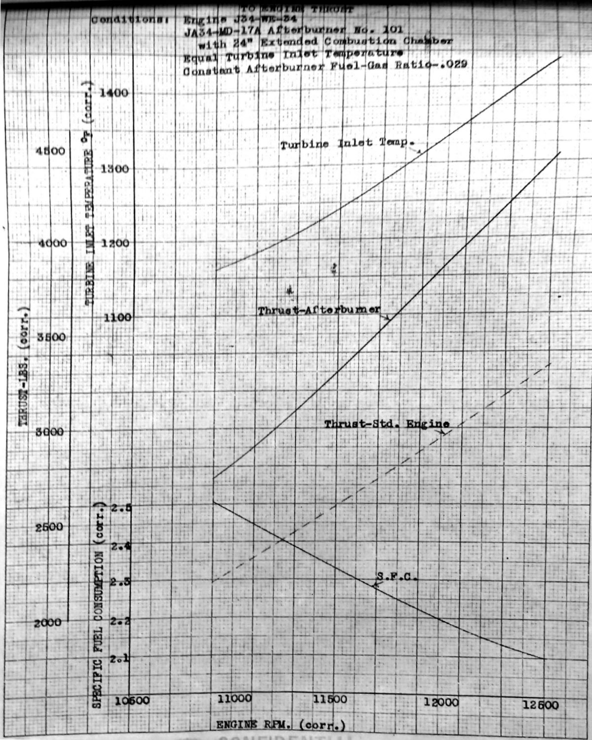
d. Only two short runs were made due to conditions. Although the data were inconclusive, the performance (Fig. 15) was recorded as follows: At Military rpm, TIT was 1,437°F, AB fuel/air ratio of 0.029, augmentation was 32.9% and the SFC was 2.1 lb/hr/lb.
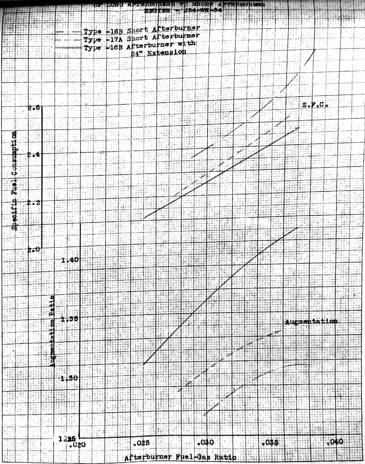
3. The JA34‑MD‑16B AB, serial No. 10, was further modified by removing the shroud and nozzle segments and installing a 260 in² fixed nozzle. A series of tests were run with the nozzle area trimmed to be 270, 278 and 287 in². The engine rpm was maintained at Military and the AB fuel varied for each nozzle area until the limiting TOT was reached. Failure of a section of the seal between the first and second stages of the turbine wheel on the engine stopped the tests before a complete calibration had been run at the 287 in² nozzle area. Figure 16 shows the results. The ‑17A was not included in the curve due to insufficient data. The test results indicated that improvement could be obtained in augmentation and SFC by extending the combustion length.
Fig. 14. JA34‑MD‑17A, serial 101 Cross Section Showing Extension and Bump Location
Fig. 15. Recorded Data from Short Tests with Long Combustion Chamber
Fig. 16. Comparison of Long to Short Afterburner Performance
20 December 1951: Contract NOa(s) 9768; Additional Afterburner Development Program ‑ Progress Report 6 October 1951 to 5 December 1951.(Last Monthly Progress Report) Development during the period consisted mainly of modifying the JA34‑MD‑17A No. 102 AB, completing the engineering on and starting fabrication of three new ABs for flight testing, these designated as JA34‑MD17B units, and calibrating engines on the McD test stand in preparation for AB static tests. Testing was resumed late in the period after receipt of six J34‑WE‑34 engines.
1. The JA34‑MD‑17A No. 103 was modified with the intention of determining the maximum augmentation possible with the AB.
a. The configuration was changed by installing a larger variable area exhaust nozzle. The range was changed from 170 – 271 in² to 217 – 321 in². The minimum was inadequate for Military non‑AB operation, but it was considered expedient to sacrifice that phase of operation to obtain a larger maximum nozzle area for testing with a minimum of rework.
b. The modified configuration was installed on engine WE200001 (the very first production J34‑WE‑34) and placed on the test stand. Only one engine run was made. No useful data was secured but further runs to determine the maximum augmentation would occur the second week of December.
c. Before the end of the report period, it was planned to increase the flameholder solidity to hopefully increase augmentation. It was hoped that “retractable” flameholders could be designed to cut thrust loss during dry operation.
2. The three JA34‑MD‑17B units, Nos. 104 – 6, were initiated. The model only differed from the ‑17A No. 103 in the corrections made to attempt to avoid the minor failures experienced on the ‑17A during the 50‑hour endurance test.
a. For cracks in the flow divider, the metal thickness on the flameholder steps face were increased.
b. The second and fourth sections of the radiation shield were replaced with sections of heavier metal and allowance was made for high operating temperatures.
c. Cracks in the nozzle segments were due to local over‑temperatures, so it was felt redesign was unnecessary. The changes in the pattern of combustion were likely to resolve the issue.
d. The cracks in the shroud fairing were addressed by reinforcing the angles that were spotwelded to the shroud fairing by extending them to form a continuous flange around the fairing, except at the streamlined bumps.
e. Engineering for the installation into F2H‑1 BuNo. 122530 was approximately 25% complete.
3. Of the six J34‑WE‑34 engines on hand, only one, WE200001, was calibrated.
Activities for the Next Period:
1. The ‑17A with its larger exhaust nozzle would be tested to determine maximum augmentation to be expected. The flameholder solidity would be increased and the necessity for artificial cooling of the variable nozzle investigated.
2. The‑16B No. 10 AB performance would be evaluated. This had the extended combustion section. The tests would be made with a 287 in² nozzle to complete the calibration. The calibration had been delayed due to the failure of the test engine, reported in the prior monthly report.
11 February 1952: Contract NOa(s)‑9022, F2H‑1, Status of Afterburner Program. Reference: (a) BuAer letter Aer‑AC‑29, 019288, dated 18 December 1951 received 21 December 1951:
1. “Reference (a) advised that BuAer planned no further action concerning installation of an afterburner in F2H‑3 aircraft of Contract NOa(s) 51‑023 and requested that the Contractor forward a contemplated program for the further development of the afterburner as authorized by Amendments 33 and 39 (under NOa(s) 9768) to subject contract.
2. “At present the Contractor plans no further afterburner development work applicable to the J‑34 engine and is compiling a final report which will be submitted to BuAer in the near future. The airplane used for afterburner testing, F2H‑1 BuNo 122530, is currently undergoing overhaul and modification to standard configuration after which it will be available for other flight test assignments.”
5 March 1952: J34‑WE‑34 Turbo‑Jet Engine with Afterburner; Request Information On. Noting that McD in the memo (above) had advised that no further afterburner development work on the J34 engine would be undertaken, BuAer asked if a J34 with an installed afterburner and the necessary controls could be made available for a project investigating pavement for jet aircraft.
9 April 1952: Authority to transfer two J34‑WE‑34 engines from Contract NOa(s) 10481 to contract NOa(s) 9022 was granted.
1 November 1952: Final Summary Report, McDonnell JA23‑MD Short Afterburner for J34‑WE‑34 Engine, McDonnell Aircraft Corporation Report No. 2568.(The key points of the summary are included here.)
Bureau of Aeronautics Work authorization trail:
1. Contract NOa(s) 6130, Amendment 2 – development of a short afterburner to augment the thrust of the J34 engines installed in McDonnell F2H airplanes.
2. Contract NOa(s) 9022, Amendment 33 – continued afterburner development and installation of ABs in a test vehicle to study the effects on weight, balance and performance.
3. Contract NOa(s) 9768, Amendment 19 – install two ABs equipped with variable area exhaust nozzles and automatic controls in one F2H‑2N airplane, which would later be assigned to the Patuxent River Naval Test Center in Maryland for tactical evaluation.
Conclusions:
1. “A short, light‑weight afterburner, in accordance with MAC Specification S‑239, was successfully developed, which exhibits the following characteristics:
a. The final configuration of the JA34‑MD afterburner, the ‑17A, is 51.4 inches in length, which is about one‑half the overall length of contemporary afterburners.
b. The actual weight of the final configuration is 218 pounds, without the control system.
c. A low non‑burning thrust loss of less than 2 percent over fixed engine nozzle at military conditions is incurred by the ‑17A afterburner installation.
d. A thrust augmentation of 34 percent over the engine with standard tailpipe and an SFC of 2.52 is achieved by the J34‑WE‑34 engine equipped with the JA34‑MD‑17A afterburner.
e. The afterburner will competently perform at over 51,200 feet altitude.
f. Afterburner ignition is established at better than 44,000 feet.
g. The JA34‑MD‑17A afterburner is considered capable of passing the afterburner portions of the endurance requirements of the qualification test set forth in Military Specification MIL‑E‑5156A by reason of its afterburning record of 13.27 hours without a failure to interrupt its operation."
2. “A fully‑automatic control system, integrating all power control functions of the engine‑afterburner combination, has been developed and has demonstrated its ability to provide reliable control and achieve optimum engine‑afterburner performance.
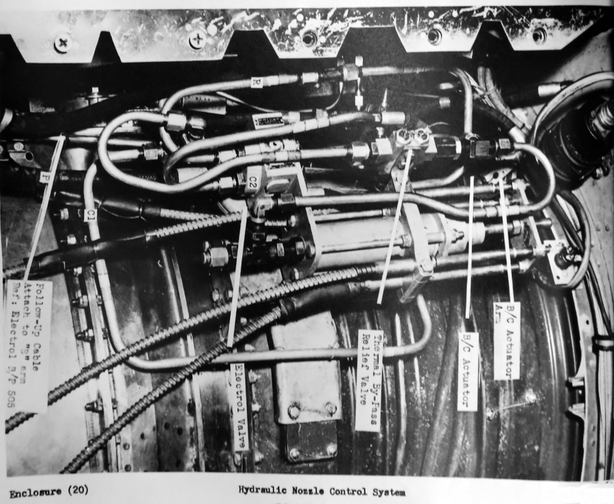
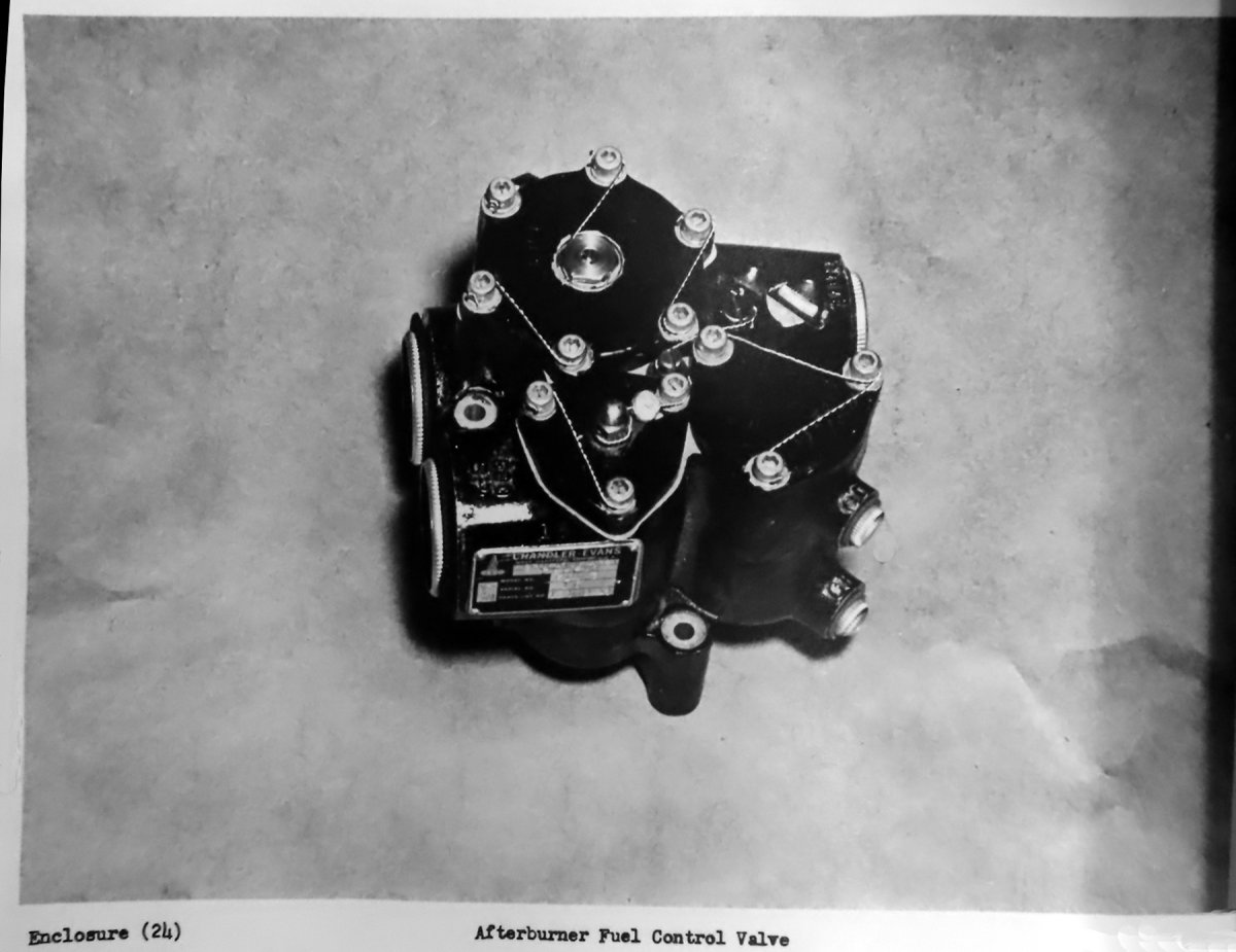
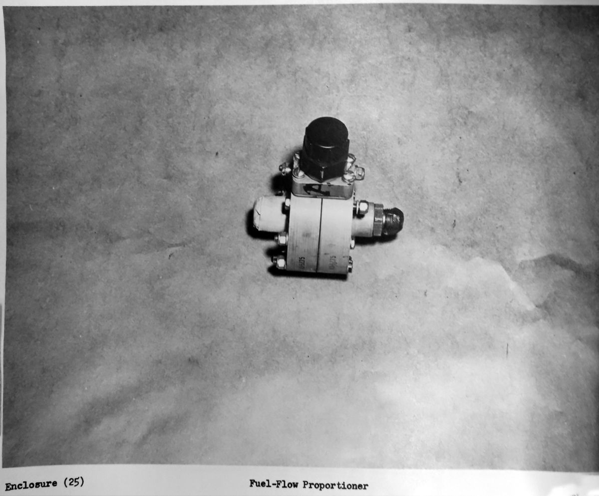
a. The final configuration of the JC34‑MD‑3 control system, consisting of a power control box, coordinating control, exhaust nozzle position regulator, emergency control system, afterburner fuel control, afterburner fuel pump, and associated fuel and air control valves, weighs 80.5 pounds.
b. Stable, accurate regulation of turbine discharge temperature by means of electronic exhaust nozzle positioning at Military engine power and during afterburning has been demonstrated in flight testing from sea level to 51,200 feet altitude.
c. Fully‑automatic afterburner ignition is assured at the altitude of 44,000 feet.
d. Successful automatic and manual switch‑over to emergency control has been demonstrated in both ground and flight test operation."
3. “The JA34‑MD afterburner is unique among contemporary afterburners because of its several innovations in design, among which are:
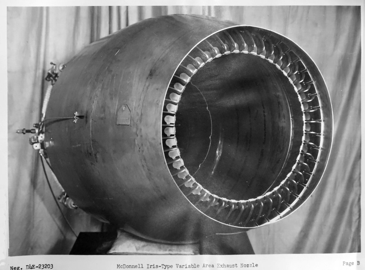
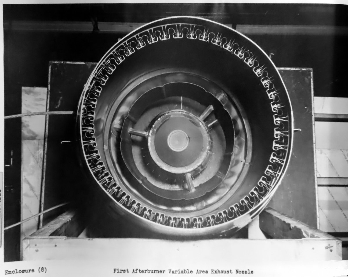
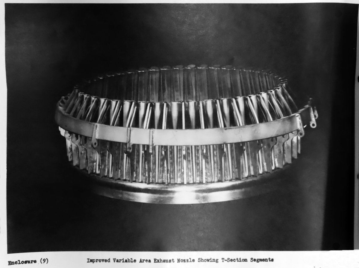
a. The iris‑type variable area exhaust nozzle, which, because it provides positive sealing against gas leakage and because of its infinite variability from minimum to maximum positions, permits continuous accurate adjustment of the exhaust nozzle, thus assuring optimum engine operation during all flight conditions.
b. The unusual combustor section, consisting of combined diffuser flameholder and spray bar fuel injection provides high efficiency with low pressure loss.
c. The movable shroud, which performs several valuable functions. By means of a unison ring, the nozzle is smoothly activated and kept in constant concentricity. The shroud and radiation shield provide an effective cooling system, reducing installation problems by permitting operation of the afterburner near aluminum structures without requiring additional protective insulation.
d. The semi‑cantilevered, bob‑weight method of mounting the afterburner to the engine, which ensures complete stability of the afterburner under operating vibrations without imposing excessive loads on the engine.
e. The floating divider‑center cone design, which reduces to a minimum the conditions conducive to failure from thermal expansion and vibration."
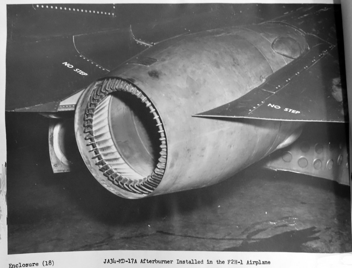
4. “The MAC short afterburner and control system in combination with a J34‑WE‑34 engine installed in an F2H‑1 airplane, supplements the power to the extent that the following marked improvements in the operational and performance characteristics of the airplane are noted:
a. Sufficient thrust is produced to double the rate of climb of the F2H‑1 airplane.
b. A 5 percent gain in maximum range is attained for the F2H‑1 airplane at cruise conditions through the pre‑selection of engine rpm and afterburner nozzle area.
c. Extension of engine operation above its normal altitude rumble limitation is afforded through control of the variable area exhaust.
d. Maximum power in an emergency such as a wave‑off is assured, because acceleration time to Military power is materially reduced."
5. "It is believed that the requirements of Contracts NOa(s)‑6130, Amendment 2, NOa(s)‑9022, Amendment 33, and NOa(s)‑9768, Amendment 19 have been adequately fulfilled.”
F2H‑1 Performance Summary
Performance Item
F2H‑1 With Afterburners & J34‑WE‑34 Engines (Flight Test)
StandardF2H‑1 with J34‑WE‑22 Engines (Flight Test)
StandardF2H‑1 with J34‑WE‑34 Engines (Estimated)
Rate of Climb at sea level (Initial G.W. = 15,200 lb)
19,500 ft/min
7,200 ft/min
8,540 ft/min
Rate of Climb at 40,000 ft (Initial G.W. = 15,200 lb)
3,500 ft/min
1,600 ft/min
1,750 ft/min
Time to Climb from sea level to 40,000 ft (Initial G.W. = 15,200 lb)
4.4 min
8.6 min
8.5 min
Vmax at 18,700 ft
509 kt
484 kt
491 kt
Vmax at 27,300 ft
493 kt
470 kt
477 kt
Vmax at 38,700 ft
470 kt
‑‑‑
‑‑‑
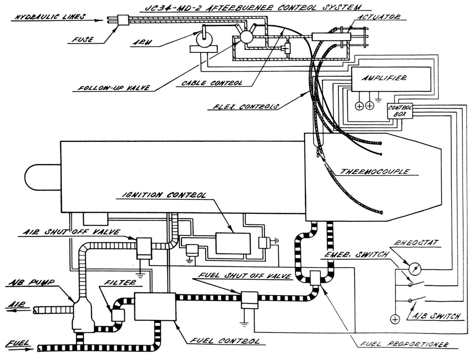
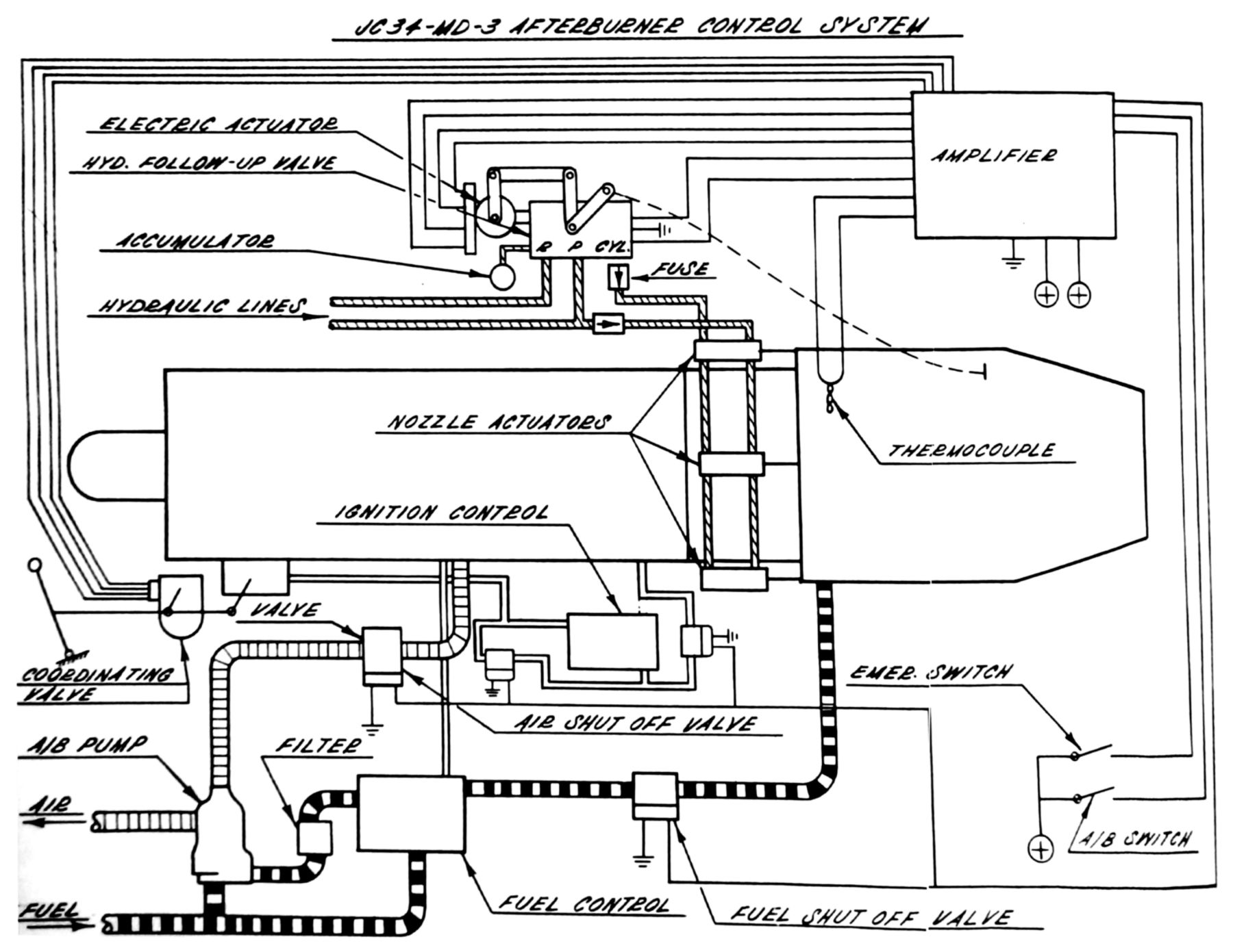
JC34‑MD‑3 Control Operation Description
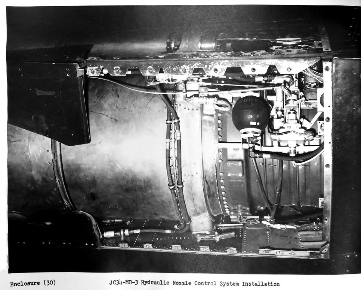
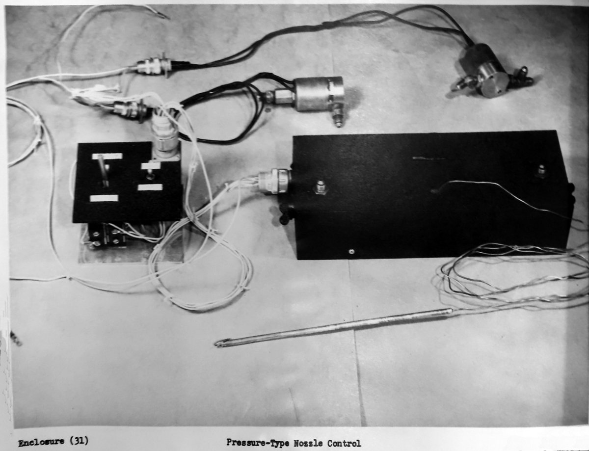
“Early in 1951, the JC34‑MD‑3, a much‑improved afterburner and engine control, was introduced and tested under Contract NOa(s)‑9768, Amendment 19. This configuration, shown schematically in enclosure 26 (see Fig. 17), uses a single power lever for all power requirements from the engine‑afterburner combination, and gives automatic temperature control for non‑afterburning engine operation as well as afterburning. With this control, the engine is started with the nozzle at its maximum area, thus helping to eliminate “hot starts”. Acceleration time is decreased, because the nozzle is held open until the engine reaches approximately 70 percent rpm. As the throttle is advanced, the nozzle automatically closes on a predetermined schedule until redline temperature is reached, at which time this temperature is reached, at which time this temperature is held automatically by the temperature control system. Movement of the power lever into afterburning range ignites the afterburner, and the temperature control amplifier controls the exhaust nozzle so as to maintain a constant turbine discharge temperature. Movement of the power level within the afterburning range modulates the thrust augmentation.”
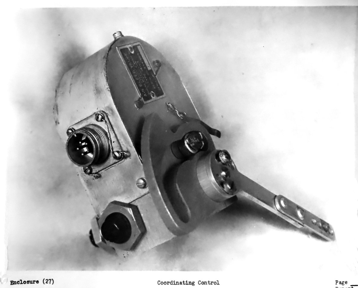
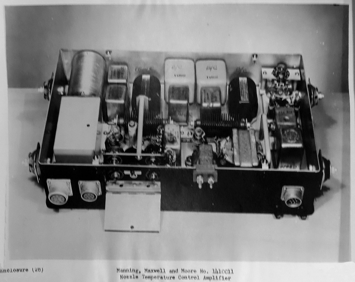
“The various functions of the control are accomplished in the following manner: The power lever is attached to a coordinating control (enclosure 27, not found) as well as the engine governor. In this unit is a potentiometer used to position the nozzle, a switch to turn on the afterburner, and a compressor pressure‑sensing bleed valve used in conjunction with the fuel regulating valve to give the variable augmentation. When the engine redline temperature is reached, the potentiometer is automatically overridden and the nozzle is positioned by electrical signals from the amplifier, as show in enclosure 28. (Not found). The nozzle is hydraulically actuated as before, but an improved … ” (balance of report not found).
Fig. 17. Enclosure 21 – JC34‑MD‑2 Afterburner Control System Schematic (for reference to Fig. 18)
Fig. 18. Enclosure 26 – JC34‑MD‑3 Afterburner Control System Schematic
Additional Photographs Included in the Summary Report
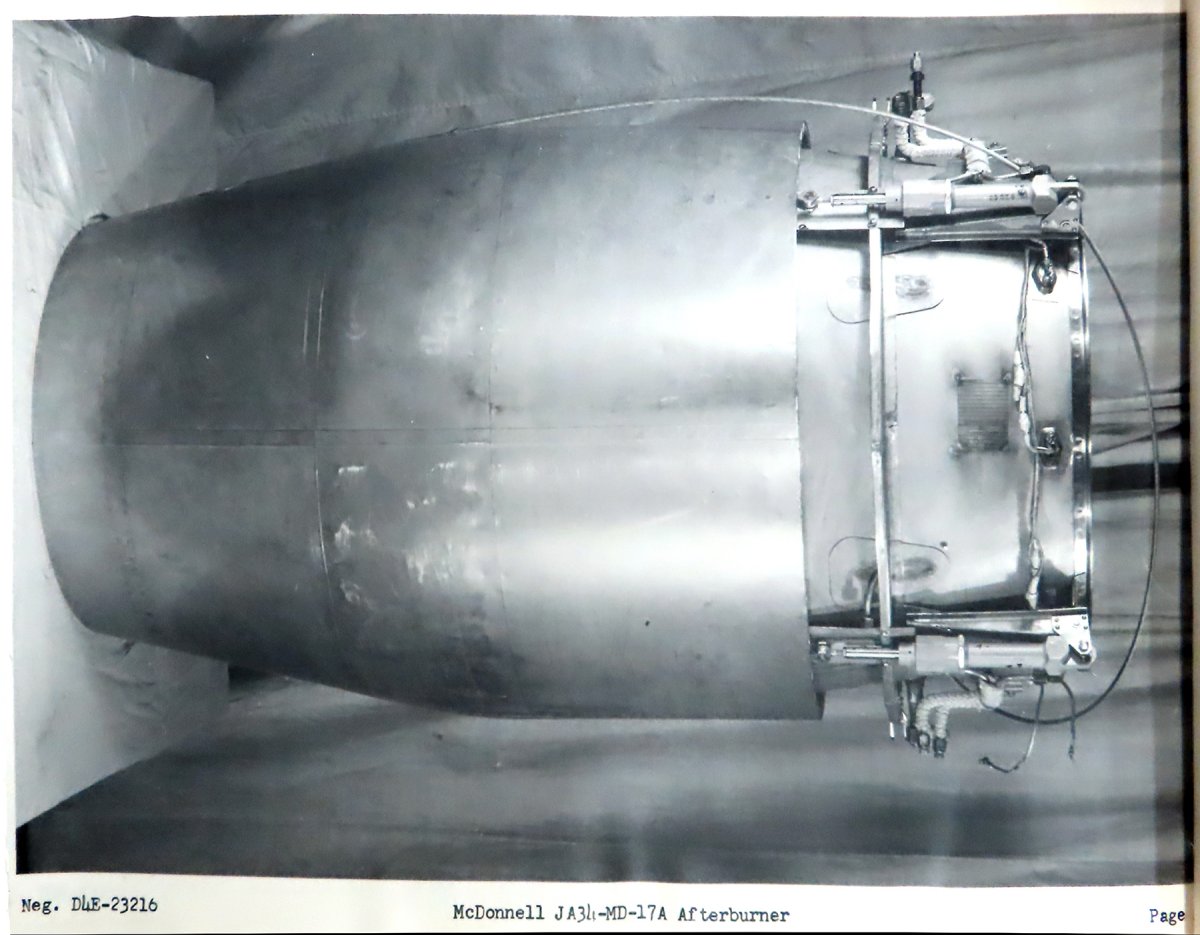
Fig. 19. McDonnell JA34‑MD‑17A Afterburner Side View (Page A)
Fig. 20. McDonnell Iris‑Type Variable Area Exhaust Nozzle (Page B)
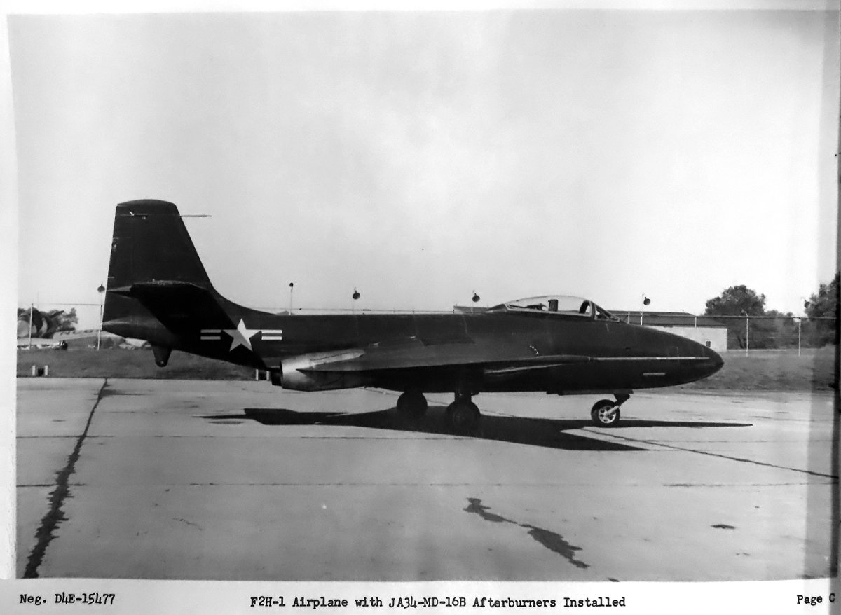
Fig. 21. F2H‑1 Airplane with JA34‑MD‑16B Afterburners Installed (Page C)
Fig. 22. Coordinating Control (Enclosure 27)
Fig. 23. Manning, Maxwell and Moore No 141CC11 Nozzle Temperature Control Amplifier (Enclosure 28)