Packard Builds the Rolls-Royce Merlin
Part 6: 1 Sep to 31 Oct 1942
Compiled by Kimble D. McCutcheon
Published 1 Nov 2026
1 Sep 1942. Production Engineering Section Chief Col O.R. Cook wired Curtiss-Wright with notification that Packard planned to equip V-1650-3 engines with downdraft carburetors and requested Curtiss-Wright's comments on this proposal. [Telegram PKS-796, Col Cook to Curtiss-Wright. 333.]
2 Sep 1942. Packard Engineering Vice President Jesse G. Vincent wrote Col Cook, reminding him that the Packard Engineering Report No. 65 Conclusion had recommended using forked connecting rods with very slightly misaligned bolt holes in production. After discussing this with Packard manufacturing, inspection and R-R Engineering Advisors, Packard had reversed this decision. There were relatively few rods in question and Packard hoped they might be used in British Meteor tank engines. Packard planned to continue inspecting to the close bolt misalignment limit set on 6 Jun 1942. [Letter, Vincent to the MatCmd Production Engineering Section. 334.]
2 Sep 1942. Vincent wrote Col Cook notifying him that the V-1650-3 Engine No. B-2 had been tested with an old 5" carburetor before it was shipped to Curtiss-Wright. That engine was being returned to Packard to be fitted with a 5.25" carburetor, after which it would be recalibrated before it was shipped back to Curtiss-Wright. Engine No. B-1 was also being equipped with a 5.25" carburetor and recalibrated before it was shipped to Wright field for calibration and a 55-hr safety test. Packard Chief Test Engineer R.N. DuBois stated the engine showed expected power as corrected for pressure altitude equal to preliminary R-R specifications. [Letter, Vincent to Col Cook. 335.]
 |
| Power Variation versus CAT |
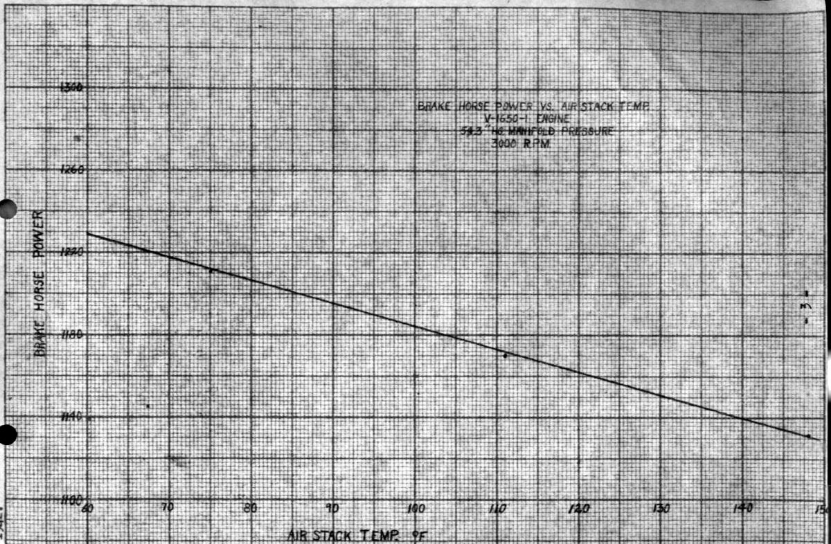
2 Sep 1942. A V-1650-1 AF No. 41-47481 test was run on dynamometer No. 11 at the Power Plant Laboratory (PPL) on 21 Aug 1942, with open exhaust stacks and atmospheric air intake. The carburetor air temperature was controlled by a heater, and the engine was run at takeoff manifold pressure and speed at various carburetor air temperatures; the exhaust was watched by the project engineer for detonation indications. A run with the mixture control full-rich using 100 octane fuel in accordance with Specification AN-VV-F-781, Amendment 4, with a rich rating of S2 + 0.2ml PbEt4 (tetraethyl lead). When running at full-rich mixture with a 148°F carburetor air temperature and 262°F mixture temperature, the engine continued to run evenly with no detonation indications. In an effort to determine safe operating limits, the mixture was leaned to 0.0805 fuel-air ratio with a 145°F carburetor; the operator noticed detonation indications in the exhaust flames. The same condition was found with a carburetor air temperature of 110°F and a 0.0785 fuel-air ratio. The air moisture content during this test was 102 grains water vapor per pound of dry air. At takeoff speed and manifold pressure, with the mixture control in full-rich, there was only a 3% power loss. PM06Fig01 shows the brake horsepower variation at takeoff with carburetor air temperatures (CAT) ranging from 60°F – 150°F. It was noted that this engine did not meet the specified takeoff power rating, but this fact had no appreciable bearing on the test.
The test engineers concluded that the V-1650-1 was free from detonation, except when the carburetor was unduly lean. If for any reason it was necessary to take off in full rich it could be done since the engine fluctuation under this condition and the power resulted in a low power loss. However, this should have been done only if absolutely necessary in some emergency. [2 Sep 1942 Memorandum Report U-EXP-M-57-8517-1. Detonation of V-1650-1 Engines at Take-Off. P172447, 336 – 338.]
3 Feb 1942. Col Carroll reported that V-1650-3 delivery dates to North American Aviation were 1 Sep 1942 for the first one and 15 Sep 1942 for the second one. [Telegram EXP-T-7988, Experimental Engineering Section to AAF Materiel Command, Washington, DC. 339.]
5 Sep 1942. The Production Engineering Section advised the Industrial Planning Section that stainless steel use in aircraft carburetors had been investigated. The idle cut-off valve body on PD-16B1 carburetors was not used on carburetors furnished to the Army Air Forces, but was used on carburetors for England to meet interchangeability requirements for British carburetors and their installations. Considerable trouble had been encountered when production was started with the valve sticking, which had been eliminated by the material combination then in use. Continued stainless steel use for this valve body was recommended. [Cross Reference 410.2 – Substitution for Nickel. 341.]
5 Sep 1942. Vincent sent Curtiss Chief Engineer Fredric Flader a V-1650-3 progress report detailing several planned improvements.
Connecting rod design, while not directly associated with the two-stage supercharger development, required improvement. Production V-1650-1 rods had an insufficient safety factor for use in the V-1650-3. Rolls-Royce (R-R) had developed a heavier rod assembly for its Merlin 61 engine with a stronger column under compression but with no bearing, bearing block or bolt diameter changes. Packard objected to producing this rod design for the V-1650-3 because it did not believe it would provide a sufficient safety factor when manufactured by Packard production methods. Instead, Packard had designed its own connecting rod assemblies based on similar rods used in Allison and Packard marine engines. Packard was seeking approval to rush 10 sets of these new rods through extensive testing in both V-1650-1 and V-1650-3 engines; Packard estimated that the first rod set would be ready in about four weeks. Vincent provided detail drawings covering this point.
The torsion spring drive designed by R-R for the Merlin 61 was not suitable for the V-1650-3. Packard Layout Drawing No. 784 depicted several changes that improved the unit's safety factor:
(a) The torsion drive shaft length had been increased by about 15%, the spline strength at both ends increased, the oil drain holes eliminated from the front end, and the shaft diameter made larger to provide approximately 5° windup under normal load in high gear.
(b) The torsion drive outer tube had been redesigned to increase the torsion capacity by 22.86% at the point midway between the splines.
(c) The V-1650-1 spline stop member had been reinstated in order to provide for 10° windup instead of the 8.5° in the Merlin 61 design. This change, along with the torsion shaft diameter change, was made to prevent hammering against the stop splines when the crankshaft was deflected due to rear-cylinder power impulses.
(d) The supercharger drive gear hub had been lengthened to accommodate the longer torsion drive shaft.
(e) A new spacing collar was added to accommodate the longer hub.
The supercharger rotor front bearing had been satisfactory in the first three V-1650-3 engines. However, a careful analysis of the conditions under which the bearing operated had indicated that a design change providing two floating bushings instead of one fixed bushing would be superior. This was shown in Layout Drawing No. 668, and the improved bearing was included in engine Nos. B-4, B-5 and B-6.
A rear breather located at a point shielded from oil thrown off from internal engine parts had proven desirable in the V-1650-1, but a design compromise had been included in the first six V-1650-3 engines. Packard proposed to change the breather design as indicated in Layout Drawing No. 646 starting with engine No. B-7.
The supercharger solenoid would be moved to the opposite engine side and mounted on an angular pad as shown in Layout Drawing No. 768. Packard thought this would ease its installation and simplify the drilled oil passages. This change was to start with engine No. B-7.
The aftercooler pump glands in the first six engines were a British automatic sealing gland that was not attractive from a production point of view. Starting with engine No. B-7, Packard planned to equip aftercooler pumps with a proven U.S. sealing gland.
Vincent offered the idea of equipping the V-1650-3 with a well-known U.S.
downdraft carburetor during a recent Wright Field conference, noting that it would have the following advantages:
(a) An air intake located below the fuselage was closer to the ground and more exposed to dirty air.
(b) The accumulation of oil on the metering venturis was thought to be eliminated with a downdraft carburetor.
(c) The downdraft carburetor installation was more accessible and provided for simplified mixture control and throttle connections
During the Wright Field conference, Vincent was directed to confer with Curtiss-Wright and North American representatives, as well as Frank Mock of Bendix Aviation Corporation. Vincent accomplished these conferences and reported that Fredric Flader, Curtiss-Wright Chief Engineer, was in favor of downdraft carburetors. R.H. Rice, North American Chief Engineer, favored updraft carburetors. While admitting the downdraft advantages stated above, he stated that the pilot's forward vision was becoming increasingly important and feared that downdraft carburetors could limit pilot's forward vision. Frank C. Mock, Bendix Director of Aircraft Carburetor Engineering and Sales, was neutral, but agreed with the above-stated advantages. Since a larger carburetor was required anyway, Mock opined that the new carburetor could be obtained more quickly if it were a downdraft type. Vincent referenced Packard Layout Drawing No. 763, which showed the proposed downdraft carburetor general arrangement; he noted that the downdraft installation increased the engine length because the metering body was located aft of the throttle body. However, the downdraft installation freed space at the engine lower rear and, in some cases, reduced interference with airframe structures. The carburetor to supercharger elbow would be rotated 180° without changing internal passage shape or fuel jet location. Packard thought MatCmd should make the final decision. If it chose a downdraft installation, that was to appear starting with engine No. B-7. In further comments regarding the carburetor installation choice, Vincent again stressed the importance of operation in dusty conditions. He hoped the question could be settled within the next two weeks so that Packard could proceed with V-1650-3 production in March 1943 and be producing 225 engines per month by May. Vincent included Packard Layout Drawing No. 762, which depicted an induction air scoop located directly under the propeller spinner and ducting to an updraft carburetor; he hoped this would throw sand and dirt clear of the cowling. This was the arrangement selected for the North American P-51B through K. On 14 Sep 1942, the Production Engineering Section recommended to the Executive for Engineering Production that all V-1650-3 engines should be fitted with updraft carburetors. [Cross Reference 452.813 – Carburetors. 356.] Packard recommended that MatCmd authorize production equipment preparation; it thought that seven months would be required for production tool-up, which would give time to thoroughly test the hand built engine and make any necessary modifications before production began.
Engine B-1, which was then at Wright Field for a 55-hr safety test, was equipped with British-built connecting rods as was engine B-2, which was on its way back from Wright Field to have a larger carburetor fitted. Once that was done, it was to be returned to Wright Field for flight testing. Engines B-3, B-4 and B-5 were also to be equipped with British-built rods so that they could be promptly released for flight testing as soon as the safety test was completed. MatCmd had given its approval to develop the U.S. type forked rod assemblies for use on all future V-1650-3 engines. [Letter, Vincent to Flader. 343 – 350.]
8 Sep 1942. Anthony J Deoutis, a PPL engineer, commented on the V-1650-3 hydraulic pump drive adapter as shown in North American Aviation (NAA) Drawing No. X101-941002 submitted with NAA letter dated 22 Au g 1942 as part of Data Transaction Report No. 50-P-735. The design was satisfactory except that the oil retainer should have been secured by a method other than staking. The drive should have been tested before approval. Since the hydraulic pump drive was an engine part, it should be furnished by the engine manufacturer and not by the airplane manufacturer. Packard had been requested to furnish a straight drive similar to that designed by NAA, but would probably be unable to furnish the drive for the first few engines. If this drive type was to be used, the type B-7 Pesco Model 349-G hydraulic pump would have to be used since it was the only one that would operate satisfactorily at a 0.808:1 speed ratio. Deoutis recommended that the hydraulic pump drive adapter designed by NAA be tested on an engine before being used in flight. If one was delivered by 21 Sep 1942, this could be done at MatCmd. If Packard used the drive as designed by NAA, provision should be made to hold the oil retainer by some means other than staking. [8 Sep 1942 Memorandum Report EXP-M-57-430-467, Hydraulic Pump Drive Assembly Design for Packard Rolls-Royce Engine V-1650-3 - XP-78 Airplane. P191517.]
10 Sep 1942. Maj A.F. Wentzel, Chief, Technical Control Branch, Inspection Section, wrote he Packard Army Air Forces Resident Representative (AAFRR) stating that the V-1650-3 that had been under test at Wright Field had failed after 11 hrs endurance running and was being returned to Packard for a teardown inspection supervised by Mr. Grimes of the Packard AAFRR office; Grimes was also to supervise the rebuild and report his findings in detail to Maj Wentzel's office. [Letter, Maj Wentzel to Packard AAFRR. 352.]
12 Sep 1942. PPL Engineer W.J. Brown summarized V-1650-3 development. The V-1650-3 was Packard's version of the R-R Merlin 61 engine. It was similar to the V-1650-1 except that it had a two-stage two-speed geared centrifugal supercharger and an aftercooler. Other desirable changes were discussed subsequently.
Engines B-1 and B-2 were the original two engines ordered by the Experimental Engineering Section. B-1 was used for special safety test to approve these engines for flight, after which they were sent to Packard for supercharger rig tests. B-2 was sent to Curtiss-Wright for XP-60 airplane installation. Engines B-3 and B-4 were ordered by the Production Engineering Section and were ultimately bound for NAA for installation in XP78, and a spare. Engine B-5 was built up from the spare parts originally ordered on contract W-535-ac-22784; it was to be used for either a model test or a spare XP-60 airplane engine. Engine B-6 was ordered by the British Air Commission. Engines B-7 and B-8 were ordered by the Experimental Engineering Section; one was to be used for a model test if it was available in time instead of engine B-5, and the other engine was to be held as a spare for wherever it was needed. Packard recommended that if more engines were required some tooling should be accomplished.
Parts on order by the Experimental Engineering Section for engine development included:
(a) Three connecting rod sets similar Merlin 61 rods, slightly modified for production purposes. One of these rods had failed during a Packard check-run; regardless, it was thought these rods would be satisfactory, and as a result, ten rod sets similar to those used in Allison engine had been ordered from Packard.
(b) The original V-1650-3 carburetors were the same as in the V-1650-1. It was found that altitude performance could probably be improved with a larger-venturi carburetor; hence, three 5.25" carburetors were ordered.
(c) Three North East magnetos had been ordered; these were the sealed type, which were expected to have better altitude performance than V-1650-1 magnetos.
(d) Three supercharger elbows to fit 5.25" carburetors were ordered.
(e) Three high-altitude ignition harnesses were ordered.
V-1650-1 engine changes applicable to the V-1650-3:
(a) A simplified camshaft drive that would eliminate numerous parts.
(b) A new coolant pump incorporating a U.S. automatic sealing gland. The present V-1650 coolant pump had to be repacked frequently to prevent leakage.
(c) Two roller-rocker arm sets; these were ordered because the old type rocker arm had not been satisfactory as the chrome pad plating had flaked off.
Packard Improvements Suggested on 29 Aug 1942
(a) Due to supercharger spring drive failures, Packard proposed modifications for all V-1650-3 engines.
(b) Packard proposed to improve the supercharger front bearing by providing two floating bushings instead of one fixed bushing; this was to be incorporated in all engines after B-3.
(c) Packard proposed to relocate the rear breather on all engines after B-6 to a better location to prevent an excessive oil quantity from being thrown out
(d) Packard proposed to relocate supercharger gear change solenoids to two-speed clutches to improve installation conditions; this was to take effect on B-7.
(e) The aftercooler pump was to be improved by incorporating a U.S. type automatic sealing gland starting with B-7.
(f) Packard proposed to equip V-1650-3 engines with a downdraft carburetor instead of the current updraft. MatCmd had not made a decision regarding this. Aircraft manufacturers were being consulted. This change would take effect on engine B-7.
Packard was to incorporate all the above items without cost increase.
V-1650-3 and Merlin 61 Testing Completed to Date
(a) In December 1941, a V-1650-1 equipped with a Merlin 61 supercharger was delivered to MatCmd for test. Numerous failures were encountered. The SU carburetor did not give correct carburetion, resulting in a burned piston. The supercharger clutches slipped and burned out due to improper adjustment. The front impeller bearing failed and terminated testing in March 1941. Packard repaired the engine, but it had not been delivered to MatCmd because there were V-1650-3 engines available for tests and there was little point in further V-1650-1 tests. At no time was it possible to stabilize running conditions sufficiently to check this engine's performance, but flash ratings were obtained that indicated the engine's output was approximately 1,385 bhp at 12,000 ft and 3,000 rpm in low supercharger gear and 1,270 bhp at 22,800 ft at 3,000 rpm in high supercharger gear.
(b) Between 22 Jun and 10 Jul 1942, the first V-1650-3 was at MatCmd for test, which was reported in Memorandum Report EXP-M-57-503-678.
[19 Sep 1942 Memorandum Report EXP-M-57-503-709. Summary of Development of V-1650-3 Engine. P192942.]
14 Sep 1942. Col O.R. Cook, Chief, Production Engineering Section wrote the Wright Field Production Engineering Chief regarding procurement of 2,000 V-1650-3 engines. On 8 Sep 1942, Packard had received a letter of inquiry regarding the procurement. Packard planned to respond by 12 Sep 1942. Packard was to submit to the Chief, Industrial Planning Section, Production Division, Wright Field on 15 September, a list of machine tools necessary to meet a production of 225 V-1650-3 engines per month. Due to the limited time available to prepare this list, it would be accurate to a possible 10% to 15% in the number of machines required. Packard anticipated producing 26 V-1650-2 engines during the fifth month after delivery of the necessary machine tools, 130 during the sixth month, and 225 during the seventh month and each month thereafter. This production rate was not in addition to the V-1650-3 production rate as evidenced in the 9J schedule. [IOM, Col Cook to Wright Field Production Division Chief. 357.]
17 Sep 1942. Expanding the reference letter that discussed the V-1650-3 and its recommended changes, Vincent established that engines B-7 and B-8 were hand-built, constructed to test the final design so that detailed drawings could be released for production tooling. At a Wright Field conference on 31 August, Vincent discussed the proposed changes with Col Page; all recommended changes were approved.
On 10 Sep 1942, Packard received telegram DE 265 stating that updraft carburetors were to be used on the V-1650-3, and Packard was requested to conduct the test program and production survey on this decision's basis. On 12 Sep 1942. Col Page told Vincent that this subject was still under discussion and there still seemed to be a difference of opinion on which carburetor configuration should be selected. Wright Field directed Vincent to be there on 15 Sep 1942 for further discussion on the subject. Soon after Vincent arrived at Col Page's office on 15 September, he received a telephone message from Frank Moch of the Bendix Corporation, who advised that Bendix was only getting 1,200 downdraft rectangular throttle bodies per month off its hydrotel machines, as compared with 1,500 per month it had expected, and for which it had accepted orders. Mock stated that it would take between a year and 18 months before it could obtain the necessary hydrotel machines to address Packard requirements if the downdraft carburetor were adopted. Later, J.E. Ellor called the Packard factory to relay the following cablegram from E.W. Hives of Rolls-Royce, which stated that R-R experience with the Vulture and Peregrine downdraft carburetors versus Merlin updraft carburetors had established no evidence in favor of the downdraft carburetors. The new R-R policy was updraft carburetors with air cleaner, which was in operation only during takeoff and was then switched to a free intake giving full forward ram after the aircraft had taken off. This was also in the Air Ministry Specification for all new aircraft. In light of the information from Mock, Ellor, plus the North American Aviation recommendations, MatCmd decided specifying downdraft carburetors would be unwise. Col Page was to discuss this matter with other MatCmd officials and give a final decision the following day.
On 16 Sep 1942, Vincent consulted Col Page and was given final go-ahead on updraft carburetors; Packard was taking prompt steps to settle the carburetor design with Bendix and obtain hand-built carburetors for installation in engines B-7 and B-8. It was understood that the new-carburetor throttle body would be similar to present production except that it would be redesigned to raise the lower flange as far as possible so as to facilitate installation of a flexible connection between the carburetor and intake scoop. Carburetor venturi bore diameters would be 5.5" as recommended by R-R. [Letter, Vincent to Experimental Engineering Section, Wright Field. 360.]
18 – 19 Sep 1942. W.J. Brown visited Packard to inspect the V-1650-3 that had failed during tests at Wright Field on 17 Sep 1942. The impeller shaft front bearing failed because sludge that had centrifuged from the oil in the impeller shaft had blocked the oil passage to the bearing; the failed bearing allowed the impeller shaft to wobble until the first impeller stage struck the diffuser housing, damaging both the first stage impeller, housing and diffuser vanes. The second stage impeller, housing and diffuser vanes were not damaged. Engine time was 95 hrs. Further supercharger drive inspection showed that the planetary gear bushings oil holes were sludged, but not enough to stop the oil flow. The overrunning clutch internal roller contact surfaces showed slight indention caused by roller bearing engagement; otherwise the drive was in good condition.
Packard proposed installing an aluminum transfer tube in the impeller shaft with a 0.156" inside diameter to supply oil to the front impeller shaft bushing. Packard also proposed to use an oil pressure of about 25 psi for the supercharger bearing instead of the 7 – 8 psi then used. To prevent excessive oil leakage with the higher oil pressure out the tail shaft bearing, the holes were to be eliminated and radial grooves substituted.
The power section from the failed engine was to be built up with the spare parts ordered on contract No. W-535-ac-22784 and returned to Wright Field for the special safety test. The damaged supercharger was to be repaired and used for development rig testing at Packard, probably as one of the slave engine then being used for V-1650-1 development. [25 Sep 1942 Memorandum Report EXP-M-57-503-710. V-1650-3 Engine Supercharger. P192940.]
19 Sep 1942. In a memorandum to MatCmd and Packard department heads, Vincent outlined his plan for the V-1650-3 supercharger rebuilding program.
Engine B-1. The power section had been disassembled, cleaned and inspected. It was to be reassembled and the supercharger installed by Monday afternoon 21 September. The aftercooler and aftercooler pump were to be cleaned and inspected by DuBois' organization. B-1's original supercharger parts were to be carefully checked and damaged parts replaced. Later, this unit was to be assembled on an experimental engine for test purposes. A new supercharger was being built from spare parts as quickly as possible; it was to include the new floating supercharger front bearing and revised oil distribution plugs as shown on Layout Drawing No. 824. As finally assembled, the supercharger impeller shaft, front bearing, driving shaft impeller gear and impeller shaft oil distributing plug were to be as shown on the latest version of Layout Drawing No. 668. The necessary supercharger impeller shaft was to be obtained by reworking the shaft intended for Engine B-5; this rework was to consist of grinding four oil grooves across the shaft rear end before installing the new distributing oil plugs. The front bearing was to be assembled with 0.002" diametrical clearance both inside and outside the floating bushings, with all bearing surfaces properly finished. A new oil pipe assembly was also required to provide intermediate oil pressure (at about 28 psi) to the impeller shaft bearings. The main drive gear and torsion drive assembly was to be replaced with the new design with 15% higher safety factor. After assembly, an acceptance test was to be run and then the engine returned to Wright Field by truck.
Engine B-2. The supercharger for this engine was to be rebuilt as outlined for engine B-1. It was to be subjected to a penalty run before shipment to Curtiss-Wright. Parts to replace the supercharger impeller shafts, front bearings, main driving gears, torsion drive shafts, etc., used in the rebuilding program were to be processed as quickly as possible. At rebuilding program completion, Engines B-1, B-2 and the B-3 supercharger would contain all improvements incorporated in Engines B-4, B-5 and B-6, except changes made to supercharger housings and impellers to incorporate the labyrinth seals between the first and second stages and steel guide vane modification. PN 601794, Cage – Supercharger Intermediate Impeller Drive Pinion (Rear), was changed to include a half-moon clearance located at the extreme outside of the four holes that carried the floating bushings. This clearance could be ground in the finished parts using a small grinding wheel with a 0.250" to 0.275" outside diameter. As the four holes were to be ground after assembly, the dimensions covering this operation were shown on Drawing No 602145, "Assembly – Supercharger Intermediate Impeller Drive Pinion Cage." These clearance openings were provided to eliminate sludge collection in the floating bushing outer oil holes and grooves. Oil passing through these openings increased supercharger driving gears.
Engine B-4. This engine was up to date except for the need to change the lubricating system for the supercharger bearings. The impeller shaft was to be removed and reworked, and the bearings installed with clearances as outlined for Engine B-1. After an acceptance test was run, it was to be shipped to North American Aviation. [19 and 21 Sep 1942 Memorandums, 364 – 367.]
19 Sep 1942. During a 31 Aug 1942 conference at MatCmd attended by Vincent, Col P.H. Robey, Lt D.M. Ross, and MatCmd engineer J.J. Rose, the endurance and flight tests conducted with AC Type 425YA, 425UUA and British-made spark lugs in V-1650 engines were reviewed. The 425YA spark plug was similar to the then-present LS47 plug except for a modified electrode construction and a greater cavity at the fire end. The 425YA plug had been subjected to flight tests in a P-40F airplane at Patterson Field at the Curtiss-Wright plant in Buffalo, New York. He performance obtained with the 425YA spark plugs at both activities was superior to that obtained with Champion LS47 production units. Vincent stated that the Curtiss-Wright test engineers considered the British-built plugs to be better than even the 425YS plugs. The AC Spark Plug Division was fabricating a reasonable number of 425UA plugs for tests to be conducted at Packard, MatCmd, and Curtiss-Wright. The 425UA plug was substantially the same as the LS47 except for a new platinum alloy ground electrode. The 425UA platinum ground electrodes were very similar to the type incorporated in recent production British 14 mm spark plugs. Large 425UA plug quantities could apparently be made available in a short time, whereas the 425YA plug would not be available for several months.
In view of the production problems and apparent immediate action required to improve 14 mm spark plug idling and oil fouling characteristics, it was agreed that AC Spark Plug Division, Packard, and MatCmd immediate efforts should be concentrated on conducting full-scale engine and flight endurance tests of 425UA spark plugs. It was understood that exhaustive full-sale ground endurance tests would promptly be made at Packard using 425UA plugs; flight endurance tests were scheduled to be conducted at MatCmd, at the Curtiss-Wright plant, and by Packard in its test airplane located at Selfridge Field. Vincent displayed a single model of an AC spark plug for use at extremely high altitudes. This new 4720A plug also employed a ceramic insulator and a new terminal end construction, that, together with the new 4270A plugs,and a redesigned ignition shielding assembly, would be submitted to MatCmd in the near future for testing. [19 Sep 1942 Memorandum Report EXP-M-57-520-291. Conference with Packard Representatives on 14 mm Spark Plugs, P160113.]
21 Sep 1942. About four grams of a gray granular foreign material removed from a Curtiss P-40F coolant drain line was submitted for analysis. About 80% was transparent crystalline particles that were colorless to dark brown, hard, and abrasive. About 15 – 20% was blue and bluish gray crystalline masses that crumbled easily, and less that 1% was ferrous and bronze metal particles. Qualitative spectrographic analysis revealed the major constituents to be silicon, copper and zinc; minor constituents were phosphorous, silver, tin, lead, aluminum, iron and nickel. Chromium, magnesium, gallium and cadmium appeared in trace amounts. The blue and gray crystalline masses and steel particles were soluble in dilute hydrochloric acid, and all but the hard transparent crystalline material dissolved in aqua regia (concentrated nitric and hydrochloric acid mixed 1:3). The hard transparent material was mostly silicon, with aluminum, iron and magnesium. Anion tests for bromides and phosphates were positive, but only small amounts were detected.
The Materials Laboratory concluded that the foreign material was approximately 80% sand, possibly due to core or blasting sand left in the cylinder head castings. The other elements comprised the remaining foreign material, which was in the form of metallic salts. Less than 1% was brass and steel. The Laboratory recommended anodizing the aluminum alloy coolant pump castings (PNs 603192 and 603218) instead of the chromic-phosphoric acid corrosion inhibiting treatment (Specification PM-1405) they had been receiving. [21 Sep 1942 Memorandum Report U-EXP-M-57-8561-1-M. Foreign Material in Coolant System of Rolls-Royce V-1650-1 Engine, AAF 41-47386. P172728, 368 – 369.]
21 Sep 1942. Vincent wrote the Experimental Engineering Section to document final V-1650-3 engineering decisions that had been discussed in Packard letters dated 29 Aug 1942 and 17 Sep 1942. The recommended changes had been approved and were being incorporated in drawings to be released for production study and tooling. These changes were to be incorporated in engines B-7 and B-8, which were to be built for model testing.
The Engine B-1 supercharger failed while running in the Wright Field altitude chamber on 17 Sep 1942. It was brought back to Packard by truck and the supercharger disassembled and made ready for inspection on 18 September. Willis J. Brown, representing the Experimental Engineering Section, was present while the failed parts were examined and was familiar with the failure, which involved hollow impeller shaft sludge accumulation. The supercharger had been operated for over 90 hrs since the impeller shaft had been inspected. The shaft front end was plugged solid with centrifuged sludge, causing the front bearing to fail due to oil starvation. A 19 Sep 1942 Packard instruction memorandum covered changes to which Brown had agreed, as documented in Packard Layout No. 668, "Revised Front Supercharger Bearing Floating Type, as revised on 19 September. This drawing showed not only the Engine B-1 construction, but also Engine B-2 for Curtiss and B-4 for North American. After Brown returned to Wright Field, a slight additional change was incorporated to make use of three impeller shafts Packard had available. Layout No. 688, dated 21 Sep 1942, showed the final impeller shaft and oil duct. Packard believed these changes would eliminate the sludge buildup and supply additional oil to the supercharger drive gears; Packard Drawing No. 602145, "Assembly – Supercharger Intermediate Impeller Drive Pinion Cage," depicted this change.
Vincent's letter also reiterated a telephone conversation with Col Page that established a 1.518:1 generator gear ratio would be used in the hand-built V-1650-3 engines then under construction. For future heavy load requirements, a ratio approaching 3.0:1 was desired. A 1.94:1 ratio was not applicable to the current generator range. [Letter, Vincent to Col Page. 370 – 372.]
29 Sep 1942. MatCmd Field Services, United Nations Branch, located in Dayton, Ohio, oversaw the production and distribution of war materiel for the WWII Allies (United Nations). During a 22 Sep 1942 conference, the British Air Commission (BAC) listed the accessories and suppliers it wanted in connection with its share of the Packard Merlin engines that would be shipped to the United Kingdom. The BAC wanted all accessories either installed on, or shipped with, each engine in the same packing case. Apparently, there was a problem of separately-shipped accessories not arriving with their engines in a timely manner. It was probable that additional costs would be incurred with this arrangement, which the BAC agreed to pay. The United Nations Branch requested that the Production Engineering Section (and others) take necessary actions to ship the engines as requested. Production Engineering requested lists of accessories for Merlin 28 and 38 engines for use in Lancaster and Mosquito airplanes so that it could follow up. [Correspondence. 377 – 379.]
30 Sep 1942. The Technical Executive from Brig Gen K.B. Wolfe, Production Division Chief's office, wired the Assistant Chief of Staff to announce Packard production plans to prioritize V-1650-3 engines, which would be produced according to the following schedule: 26 in March; 130 in April; 225 in May and every month thereafter. These production increases over the then-current 80 engines per month was contingent on receiving machine tools that were being diverted from less urgent projects. [Telegram PROD-T-430. Gen Wolfe to Assistant Chief of Staff. 380.]
1 Oct 1942. 1st Lt Lloyd E. Kinkade commented on an unsatisfactory report No.42-112 dated 1 Jul 1942. The engine was received by the PPL from Fairfield Air Depot; it was torn down and inspected. The carburetor was extremely dirty and Lt Kinkade thought it had been running lean as the valves and pistons showed signs of detonation. The pilot had reported that the carburetor heat was in the "hot" position when he checked his controls. Lt Kinkade concluded the engine cutting out was probably due to a very lean carburetor, caused by dirt, and hot carburetor air. No action was to be taken other than recording the unsatisfactory report for future reference. [1 Oct 1942 Memorandum Report U-EXP-M-57-8607. V-1650-1 Engine, A.F. No. 41-46550, P-40F Airplane, A.F. No. 41-13619. P72880.]
3 Oct 1942. Contract Section Chief Col A.E. Jones informed Packard of a Curtiss-Wright preliminary design study using the V-1650-3 in a fighter project of interest to MatCmd. He authorized Packard to furnish such general drawings, specifications and other data needed in connection with the design study. While absolute V-1650-3 ratings had not yet been established, the engine performance obtained during a Wright Field test was thought adequate. [Letter, Col Jones to Packard. 384 – 385.]
9 Oct 1942. Packard Vice President W.M. Packer wrote Col A.H. Johnson confirming a 7 October review with the Industrial Planning Section of the machine tools required to increase Packard aircraft engine production from 800 to 900 per month in January 1943, in line with the 9-J schedule. The review included consideration of all machines that could be diverted to Packard; machines special to Packard on which work must be started at once if the schedule was to be met (not possible with Packard's low 115 urgency rating; the strong likelihood that machines with promised delivery dates would be further delayed due to the low urgency rating. Packard deliveries had been delayed an average of 60 days from its previous delivery promises. While Packard continued to process with the Industrial Planning Section each successive production increase (900 to 1,000; 1,000 to 1,200; 1,200 to 1,400) to be achieved by June 1943, the promises made to Packard on machine tools indicated that production from 800 to 900 could not take place until May or June; if further machine tool deferments occurred, the production increase dates would be set back accordingly. The same applied to any increase in spare parts above the original order, which was based on 17% of the engine contract.
At that point, the engine was subcontracted 50% by dollar volume, 68.6% by part number and 80% by part count. Although Packard was working with the Industrial Planning Section to obtain further outside sources, experience indicated no likelihood that outside added capacity would have any effect on production increases before May or June 1943. [Letter, Packer to Col Johnson. 387 – 388.]
9 Oct 1942. Discussions between the Experimental Engineering Section and Packard had established the desirability, from a production standpoint, of using the V-1650-3 two-speed supercharger drive and bearings as detailed on Packard Drawing No. 679. Col O.R. Cook requested that Packard build two such engines and subject them to model tests as soon as practicable. Col Cook also requested that Packard estimate the number of machine tools eliminated from Packard's requirements if this supercharger drive were to be adopted for all Packard production engines. [Letter. Col Cook to Packard. 390.]
14 Oct 1942. Anticipating a contract to build R-R engine with an improved two-stage, two-speed supercharger designed by Vincent, Packard Vice President Milton Tibbetts wrote Col A.E. Jones, Chief, Contract Section, to obtain royalty rate approval for four patents related to the two-speed supercharger drive. Vincent had been in close contact with Col Page, who was cognizant of the technical and contractual details. According to Tibbitts, Wright had cooperated with Packard's supercharger development and had offered a discounted license for same. Wright made no royalty charge for spare or replacement parts. Wright offered a range of $0.30 for drives used on 100 hp aircraft engines to $2.00 for use on 1,000 hp engines, plus $0.10 for each additional 100 hp or fraction thereof. If Packard made drives for other than the United States, the royalty was to be $9.00 per drive, with the output described as follows:
In determining horsepower, the manufacturer's guaranteed horsepower output for protracted periods (full throttle at rated speed and critical altitude) of the aircraft engine for which the supercharger drive assembly was designed or intended to be used, was conclusive.
Patents covering the proposed license were:
| Patent No.M. | Title | Issue Date |
|---|
| 2,034,087 | Two-Speed Supercarger Drive | 17 Mar 1936 |
| 2,101,239 | Supercharger Drive | 7 Dec 1937 |
| 2,110,711 | Two-Speed Supercharger | 8 Mar 1938 |
| 2,263.453 | Two-Speed Supercharger Drive | 8 Nov 1941. |
Wright thought the royalty rates reasonable and requested that MatCmd approved Wright's suggest license schedule. [Letter, Col A.E. Jones, Contract Section Chief to Packard. 393.]
19 Oct 1942. Vincent wrote NAA Chief Engineer R.H Rice alerting him of a change scheduled for V-1650-3 engines B-4 and B-5 before they could be used for flight testing. Engine B-4 was already at NAA and B-5 was being completed. During engine B-1's recent testing in Wright Field's altitude chamber, the first stage impeller had rubbed in its housing and Packard intended to increase its clearance to account for extreme expansion and contraction. Packard thought it unlikely that this would cause trouble with B-4 if it were only used for ground running to check cooling and other installation items. Parts for engine B-5 were to be completed on 20 October and Packard promised to rush B-5 through assembly and test, and ship it before month end. Engine B-4 would have to be returned to Packard for modification, which Vincent expected to be complete in a few days, after which it would be returned to NAA.
NAA planned to use Packard PN 609789 15° aftercooler outlet connections and rubber seals on the expansion tank provided by Packard, and two had been ordered. These were not in stock, but Packard was expediting their manufacture and planned to ship them via air mail as soon as they became available. Vincent sent a similar letter to Fredric Flader at Curtiss-Wright concerning engine B-2, which was then at Curtiss-Wright; it was also to be returned to Packard for modification. [Letters, Packard to NAA and Curtiss-Wright, with copies to MatCmd. 399 – 403.]
20 Oct 1942. Col Carroll cabled Packard requesting original R-R crankshaft blueprints with detailed dimensions of the barreled bores for use in connection with crankshaft studies being made at MatCmd.[Telegram EXP-7294, Col Carroll to Packard. 404.]
22 Oct 1942. Col Cook wrote the PPL stating that no automatic engine regulator had been developed for the V-1650-3 and that the present automatic manifold pressure regulator did not maintain a given manifold pressure setting, but prevented an allowable manifold pressure from being exceeded. In contrast, the Allison V-1710 manifold pressure was superior because it DID maintain a given manifold pressure. Col Cook requested that an automatic V-1650-3 engine regulator be developed as soon as possible since many P-51 airplanes were to be powered by V-1650-3 engines. [IOM, Production Engineering to the PPL. 406.]
Generator Drive Coupling
 |
 |
| PM06Fig03 |
PM06Fig04 |
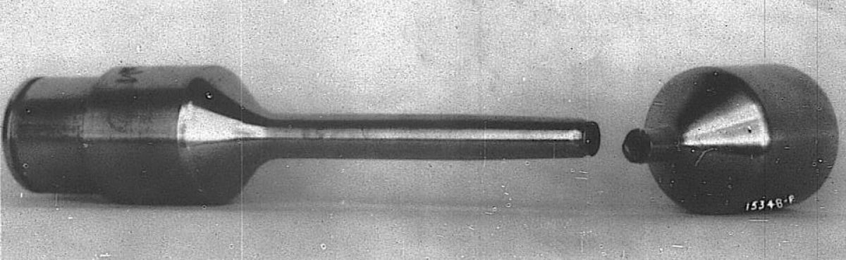
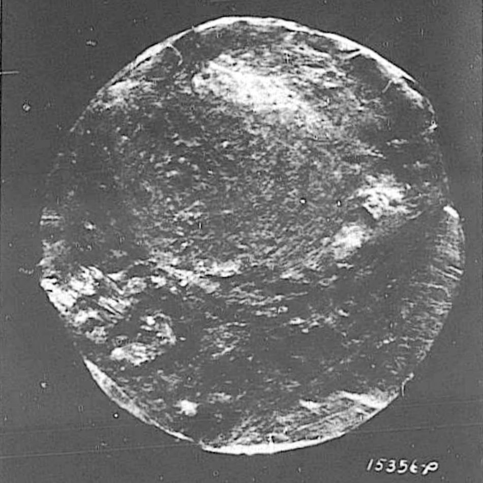
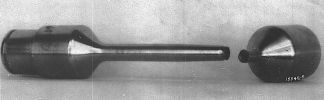
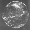
22 Oct 1942. Unsatisfactory Report No. 42-111, Air Service Command Serial No. 42-15503, dated 3 Aug 1942, stated that upon discovering the generator inoperative an inspection revealed the PN 604026 generator drive coupling had sheared at its smallest diameter. The failure, which occurred after 16:25 engine operating hours, was thought to be induced by shaft misalignment. As this was an isolated case, no further action was taken. [22 Oct 1942 Memorandum Report U-EXP-M-57-8589. Generator Drive Coupling Shaft Failure, V-1650-1 Engine, A.F. No. 41-47158. P172645.] As part of this investigation, the broken shaft was examined by the Materials Laboratory, which determined the shaft was made of AMS 6310 steel with a 28 – 33 Rockwell "C" drawing specified hardness and which tested 32 – 33 Rockwell "C". The generator drive coupling shaft between the splines had a 0.437" diameter for most of its length. Near the engine end it tapered from about 1.0" to 0.375" diameter, where it was filleted with a 0.05" radius to 0.3125" diameter. The shaft failed at this smallest diameter just beyond the fillet as shown in PM06Fig03. Microscopic fracture examination revealed numerous lines running concentric to an off-center spot, as seen in PM06Fig04. The circular spot, off-center about 0.06" with a 0.10" diameter, was probably the last place to break. The fracture edge was battered and worked, with several minute cracks entering the break surface. Because of this bettered condition that resulted from the broken surfaces rubbing, exact failure diagnosis was impossible. However, the least damaged fracture portion suggested that the failure occurred in fatigue or torsion (PM06Fig04). The fracture eccentricity may have been due to the generator mating spline being slightly off center, which would have concentrated the eccentric stress in the notched section. [9 Oct 1942 Memorandum Report U-EXP-M-57-8589-M. Generator Drive Shaft from Rolls-Royce V-1650-1 Engine, AAF No. 41-47158. P172640.]
28 Oct 1942. Packard Vice President W.M. Packer wrote the Production Engineering Section, covering an analysis of all V-1650-1 field service complaints received during September 1942 (only the cover letter, the actual complaints were not in the file). This analysis included:
1. A summary showing the number under each heading.
2. Complaint details, such as engine number, time and place, engine hours and pertinent facts.
3. A report of J.R. Ferguson, Chief Production Engineer, on a service complaint meeting held on 19 October and attended by representatives of the Packard engineering, inspection and service departments. At this meeting, all September service complaints were discussed and a service complaint report was developed that showed the complaint and steps taken to overcome or eliminate each complaint.
4. Packard made requests via Air Service Command for certain engines to be returned to Packard for inspection and overhaul so the reason(s) for reported trouble could be determined.
5. Packard also requested that magnetos found defective during this analysis be returned to Packard for study.
6. A similar meeting was planned for October as soon as the information was compiled.
[Letter, Packer to Maj Orville E. Mohler. 408 – 409.]
28 Oct 1942. Vincent wrote the Experimental Engineering Section stating that engine B-1 had been rebuilt with minor modifications to address the trouble encountered during recent altitude chamber tests. He attached a parts list to record the B-1 parts history. [Letter, Vincent to Experimental Engineering. 410 – 412.]
29 Oct 1942. Col Carroll wrote Packard stating that MatCmd was anxious to expedite development of a variable datum boost control for V-1650-3 engines, and requested that Packard report on its progress with this development. He noted that future controls would include engine speed control, which meant that the location and design of the automatic boost control should be such that a speed control could conveniently be added at a future date. [Letter, Col Carroll to Packard. 415.]
30 Oct 1942. Production Engineering noted that Packard, having developed a new connecting rod that increased the factor of safety and was simpler than the one then in production. Both MatCmd and the BAC had approved the design, which was being model-tested at Packard. Anticipating the new rod would pass the model test and would be immediately approved for production, the writer recommended that every effort be exerted to provide Packard with adequate machine tools for production. Packard was to be contacted regarding its need for tools so as to expedite production. [Cross Reference No. 452.8 – Packard V-1650. 416 - 417.]
31 Oct 1942. PPL Chief Col Page wrote the Experimental Engineering Chief stating that the hydraulic pump drive designed by NAA for its P-51 airplane and depicted on Drawing No. X101-941002, had been tested by Packard, which reported that it did not contain sufficient grease for long operating periods. Packard revised the design to remedy this condition. Since only two drives were to be used, Col Page recommended checking the grease level every 25 hrs. Only one hydraulic pump type would operate satisfactorily with this slow speed drive, the Pesco Model 349G, Type B-7. [IOM, PPL to Experimental Engineering. 418.]