Packard Builds the Rolls-Royce Merlin
Part 4: 1 Jan – 30 Jun 1942: V-1650-1 into Production and Service
Compiled by Kimble D. McCutcheon
Published 1 Sep 2026; Revised 21 Sep 2026
5 Jan 1942. Lt Col Page telephoned Vincent with news that the British Air Commission (BAC, a U.S. organization created under the British Purchasing Commission to manage British orders for airplanes, engines, and aircraft supplies) had approved a Packard-Merlin version with an extension shaft: "We agree to your obtaining from Packard and Rolls-Royce Merlin engine with the propeller drive at crankshaft speed, which engine you require in order to obtain intelligent vibration test of the engine in combination with the extension shaft and gear box as used in the [Bell] P-39 airplane. Agreement is subject to the following conditions:
1. That full information be made available to us and that we shall have the right to use without charge whatsoever any of the information which emerges from the proposed order and test.
2. That the development work shall be done in close collaboration with the Rolls-Royce representative at Packard and that the Technical Department of the BAC, and their approval is obtained on the design and installation before tests are carried out.
Lt Col Page read another portion of the telegram: "This office has contacted Packard concerning providing a crankshaft speed propeller drive on the Packard built Rolls-Royce V-1650 engine for test with an Allison extension shaft and gear box as used on the P-39 airplane. This project suggested to check torsional vibration of the engine with this drive. The Change is quite a simple one but Colonel Vincent reports it will be necessary to obtain British approval before a proposal can be made to Wright Field. Recommend this approval be obtained as this engine, particularly with two stage supercharger, might be exceedingly attractive in P-39 airplane if the vibration problems are not insurmountable." This meant that Packard could immediately begin work on this Packard-Merlin version. MatCmd had asked for authority to proceed on a separate experimental contract. Vincent was pleased to do the work at Packard because "… we could do it for half the price." The tools for cutting the splines were special; all the grinders were set up and Packard could put the gears through the grinder in 15 minutes.
Vincent changed topics to the Packard-designed supercharger drive. Upon reflection, Vincent had remembered that Wright Aeronautical used an overrunning clutch in its supercharger drive design that would be ideal for the Packard drive. Vincent had telephoned Arthur Nutt, the inventor, and received his blessing to use the Wright overrunning clutch in the Merlin. Vincent thought it a win overall for Packard to buy the overrunning clutches from Wright. This scheme would also facilitate a fully automatic shift at a preselected altitude. [Telephone Conversation Transcript, Col Page to Vincent. 1 – 5.]
9 Jan 1942. Maj Dean B. Belt wired the Air Corps Central District Supervisor requesting that the Packard Resident Representative be informed that the V-1650-3, Mfg. No. A-9, Air Corps (AC) No. 41-50437, was being returned to Packard to repair damage suffered during testing at the PPL. The Experimental Engineering Section wanted the parts replaced to be entirely at Packard's discretion. [Telegram THX-INSP-514, Maj Belt to Air Corps Central District Supervisor. 7.]
9 Jan 1942. A Wright Field Production Engineering Section cable requested information as to whether the 240 Packard Rolls-Royce engines on Army contract to be released to the Canadian Government for installation in Hurricanes were to be delivered as V-1650-1 or Merlin 28 types (notice the change from the Merlin XXVIII designation). Also, would these be transferred on a Defense Aid Requisition? [Telegram PROD-T-623, Production Engineering Section to the Technical Executive. 8.] A 16 Jan 1942 Contract File W-535-ac-15678 Cross Reference recommended release as either V-1650-1 or Merlin 28, as a third type would greatly increase production difficulties. [Cross Reference No. 452.8 Rolls-Royce Packard V-1650 Engine. 14.]
13 Jan 1942. The Experimental Engineering Chief requested the total weight and overall dimensions of the two-stage supercharged Packard Rolls-Royce engine then on test at Wright Field. [Telegram PP-278, Chief, Experimental Engineering Section to Lt Col Page, PPL. 9.] PPL responded the same day that the overall length was 85.8", the width was 30.2 ", and the height was 45.725". Dry weight was 1,690 lb. [Telegram EXP-T-1 71, PPL to Experimental Engineering. 10.]
15 Jan 1943. Lt Col Carroll wrote Packard's DuBois stating MatCmd's desire to keep all V-1650-1 spare parts with the test engine, Mfg. No. A-4, AC No. 41-46522, which had been returned to Packard. After type test completion the Division had the following spare used parts on hand: one coolant pump, three pistons, one spring drive, two magnetos and one carburetor. These parts were then at MatCmd. [Letter, Lt Col Carroll to DuBois at Packard. 16.]
16 Jan 1942. Lt Col Carroll wrote Vincent with news that on 8 January Daniel McGrath, Eclipse Aviation Company representative, had taken the V-1650-1 starter drive shaft, hand crank gear and motor driven gear for analysis after they had failed at Wright Field. McGrath was to return these parts to Packard once his analysis was done. [Letter, Lt Col Carroll to Vincent. 17.] The V-1650-1 after it had been shut down for eight hours in sub-zero weather. Several attempts to start the engine were made; the starter motor was running but the engine was not turning over. The starter had been removed and the drive shaft between the reduction gear and bevel driving gear had sheared. The hand crank gear was also showing signs of failure. [Letter, Lt Col K.B. Wolfe to Vincent. 20.]
20 Jan 1942. Lt Col Carroll supplied 1st and 2nd indorsements to Drawings Nos. X4206921 and X42V8124, which detailed modifications to AC No. 40K3911 Stand, Assembly, Engine Overhaul for Packard Merlin Engines. A Drawing No. X42G6921 was returned with a request that detailed drawings be made covering the front and rear plate outlined on this drawing, in order that procurement data would be accessible to Contract Section for a consolidated procurement of these plates, which would be applied to stands now in service. Lt Col Carroll requested information to the approximate date drawing copies could be expected so that initial procurement could be made and the same furnished the Service with the least practicable delay. [27 Dec 1941 IOM from E.E.S, Lt Col J.H Hicks, Air Corps Chief Field Service Section to War Department, Air Corps, Air Service Command, Field Service Section, Wright Field, Dayton, Ohio. 11 – 12.] Lt Col Carroll, in another IOM, covered Modification of Stand Assembly Engine Overhaul PN 40K3911 for Packard Merlin Engine, comprising adapter plates for fitting the Merlin engine to existing Air Corps engine stands. [IOM, Lt Col Carroll to Chief, Field Service Section, Air Service Command, Wright Field. 13.]
21 Jan 1942. Lt Col Wolfe requested that Packard send exhaust flange drawings for the Merlin 28 to Wallace Supplies Manufacturing Company, which was to fabricate flanges or perhaps complete exhaust stacks/systems. [Telegram, Lt Col Wolfe to Vincent. 21.]
21 Jan 1942. Commenting on Memorandum Report EXP-M-52-580-68-2, Vibration Survey of a Curtiss 89301-3 Propeller on a Packard V-1650-1 Engine Propeller Vibration Test No. 88, the Propeller Laboratory concluded that vibratory changes of stress in excess of the limit considered safe for use existed, and recommended that further tests be made in flight. [Cross Reference No. 452.025 Curtiss Propeller. 22.]
29 Jan 1942. Packard sent the PPL two reports dated 26 Jan 1942: No. 31. Teardown Inspection of Engine A-9 (Merlin 61) on return from Wright Field Army Air Corps Test and No. 32. Testing of Engine No. A-9 Converted to Merlin 61 Type After Rebuild of 20 Jan 1942. [Letter, DuBois to PPL. 23.] Unfortunately, only the cover letter exists; the reports are missing.
31 Jan 1942. An A-1a priority rating was assigned to the allocation of material and manufacture of all tools listed in the 20 Jan 1942 IOM, which made up the special tool kits furnished with Packard Merlin engines. [Cross Reference 452.8 Packard Rolls-Royce Engine. 24.]
7 Feb 1942. AC Inspector J.R. Volmer wrote the Chief, Production Engineering Section regarding Materiel Division Field Organization Memorandum No. 7, dated 12 Jan 1942, which stated, "All questions regarding the conductance of engine model test not involving contract requirements will be referred to the Chief, Inspection Section for decision. Other decisions reached by other sections regarding tests being witnessed by the Model Test Unit will be referred immediately to the Chief, Inspection Section, in order that the model test personnel concerned may be properly informed." Volmer requested that during telephone conversations with Packard about the V-1650-1 originating from production engineering, the proper Inspection Section personnel were to be included on a conference hook-up for their concurrence. Volmer had asked Packard to coordinate telephone calls thusly. [Letter, Volmer to Production Engineering Chief. 25.]
12 Feb 1942. Preliminary steps had been taken to furnish Packard with a contract to modify a V-1650-1 with a propeller drive incorporating a flange for an extension drive and a torsiometer drive. 27.]
14 Feb 1942. The following accessories were furnished with Packard V-1650-1 engines for the Air Corps:
PD-16A1 Carburetor
BTH-C5 Magnetos
Automatic Boost Control
24V Special Electric Starter
G-9 Fuel Pump
AC Type 417-H Spark Plugs,
Exhaust Flanges and Gaskets
Separate Oil Filter
The separate oil filter was the R-R type but due to difficulties with it on P-40F airplanes a CUNO filter was being considered instead. A hand starting crank had also been furnished with the engine, but this item was being deleted because Curtiss was furnishing a standard Air Corps crank with the airplane. [Telegram Prod-T-516, Production Engineering Section to PPL. 28.]
17 Feb 1942. PPL ignition specialist T.T. Neill commented on a 6 Jan 1942 letter and 9 Jan 1942 Drawing and Data Transaction Report No. G-42-304 from the Packard Air Corps Inspector. Various tests made by MatCmd on AC 417H (LS-47) spark plugs had shown them satisfactorily smooth when installed in a V-1650 engine in an airplane, confirming tests made by Packard comparing the AC plugs to British designs. The rough operation mentioned in the inspector's report was probably due to engine mounting. Some engines were very sensitive due to mixture distribution, a phenomenon that was accentuated by mounting and could cause excessive vibration. The AC 417H (LS-47) spark plugs gave satisfactorily smooth V-1650 operation and apparent roughness on the dynamometer was not cause for rejection; the Packard inspector was advised of this. [17 Feb 1942 Memorandum Report EXP-M-57-503-526. Spark Plugs for V-1650 Engine. P153040.]
20 Feb 1942. Col Wolfe cabled Packard with news the V-1650-1 engine tool kit submitted for inspection had been found satisfactory except that it did not include a spark plug wrench. The tool kit was being returned to Packard. [Telegram, Col Wolfe to Packard. 31.]
21 Feb 1942. The propeller laboratory requested assignment of a Curtiss P-40F with a V-1650-1 to determine flight response and general operating characteristics of the English-built Rotol hydraulic propellers with various types of wood blades. [Cross Reference 452.1 Curtiss P-40F Airplane. 32.]
21 Feb 1942. The BAC contacted MatCmd about modifications to Packard engines (changes in radiator location, coolant pump outlet, and cylinder block inlet), which were being built under British Contract A-787, so that they could be used in Canadian-built Mosquito aircraft. According to BAC, these changes would have no impact on power output. A total of 960 engines were affected, and the modified ones would be designated Merlin 31. [Teletype E-981. 33.] In a 24 Feb 1942 wire, Production Engineering amplified the earlier description by stating that the modifications consisted of deleting the connection from the coolant pump outlet to cylinder block and substituting a connection from the coolant pump to radiator, then to the cylinder block. Production Engineering concurred with this modification and was initiating action to authorize Packard to make the modifications. [Telegram PROD-T-775. 35.]
21 Feb 1942. Experimental Engineering was preparing to test three British Rotol hydraulic propellers, including engine tests and aircraft flight test. These propellers were intended for use on British No. 5 splined shaft with double oil lines from the propeller to the governor. Experimental Engineering requested two V-1650-3 engines with British nose sections equipped as described. These engines were to be used at Wright Field and would be returned when the testing was complete. In his 1st Indorsement, Col Wolfe agreed to furnish the two engines with Merlin 28 reduction gears and propeller shafts. [Letter, Col Carroll to Chief, Production Engineering. 34.]
28 Feb 1942. Contract Section decided a complete overhaul tool set was superfluous for present PPL needs and requested a list with estimated unit cost and delivery date for tools necessary for Merlin inspection, teardown and assembly. [Cross Reference 413.1 Packard Engine Tools. 36.]
3 Mar 1942. R&R Sheet 1-29-41 referenced 29 Jan 1942, Adaptation of V-1650-1 Engine to Stand Assembly, PN 40K3911, which had been coordinated with PPL and Dwg. 20K3911, was to be revised as listed. Engine Overhaul Stand, Dwg 40K3911 [Cross Reference 413.1 Engine Overhaul Stand. 37.] Packard replied to this on 30 Mar 1942 stating that a proposal was being prepared but that it would be delayed by about 45 days because design work had not been completed on 50 out of 221 items that would make up a complete set. Packard was aware of the urgency and claimed to be doing everything possible to expedite the proposal. [Letter, Packard to Col Echols. 51.]
3 Mar 1942. C.H. Vincent, Packard Aircraft Engine Division Service Engineer, wrote Col Carroll regarding the V-1650-1 starter. The Eclipse starter had failed because the hand crank assembly had been installed with the gasket missing or of insufficient thickness. Since the hand crank gear was continuously in mesh with the starter gear the lack of backlash had resulted in overheating and seizure of the parts. The proper backlash, according the Table of Limits, Reference 234, Chapter 4, was 0.002" – 0.006", with 0.014" noted as the maximum worn limit. [Letter, Packard to Air Corps Factory Representative. 38.]
4 Mar 1942. Col Carroll wrote the Field Service Section Chief, alerting that Section that clamp drawings Nos. X42B1142, X42B1143 and X42B1144 had been released and would be added to the V-1650 engine transportation cradle drawing 38K436. Clamp drawings XB42B1145, XB42B1146, and XB42B1147 had been prepared allowing a split clamp that could be fabricated and installed on the present engine cradles without any rework. These drawings were to be used only for equipping the 38K436 cradles in service of transporting the V-1650 engine. [Letter, Col Carroll to Chief, Field Service Section, Wright Field. 39.] On 14 Mar 1942, these drawings were updated and the numbers changed to X42A11142, X42A11142-1, X42A11144, X42A11145, X42A11145-1 and X42A11147, thereby superseding the previously-assigned numbers. [43.]
10 Mar 1942. In a 28 Feb 1942 letter and Report No. P-40-189, Packard had recommended plugging V-1650-1 supercharger volute drains. PPL civilian engineer W.J. Brown objected to this because of the danger of loading the cylinders from excessive priming. It had been established that oil draining from the supercharger volute affected carburetor fuel/air metering and provisions were to be made to drain the supercharger volute overboard when the engine was not running and to drain it into the supercharger inlet above the carburetor when the engine was running. This supercharger volute draining method was used by most American engine manufacturers. Brown strongly recommended leaving the drain open unless the contractor could prove that excessive priming would not load up the cylinders. [10 Mar 1942 Memorandum Report EXP-M-57-430-384. Plugging of Supercharger Volute Drain in V-1650-1 Engine - P-40F Airplane. P141583.] During a visit to Packard on 24 Mar 1942, a MatCmd representative discovered that Packard tests had established that oil draining from the supercharger volute collected on the pressure carburetor boost venturi, affecting fuel metering. Packard had also found that by installing a tube in the carburetor on the supercharger volute drain outlet that oil and gasoline draining from the supercharger could be brought in above the boost venturi, eliminating oil collection on the boost venturi and still allowing the supercharger to drain properly. The representative recommended that carburetors be reworked to incorporate a supercharger volute drain that entered above the boost venturi. [9 Apr 1942 Memorandum Report EXP-M-57-430-384 Addendum 1. Plugging of Supercharger Volute Drain in V-1650-1 Engine - P-40F Airplane. P141582.] Packard subsequently ran tests with the engine tilted upward 15°; with 10 primer strokes only 15cc of fuel drained from the volute in 1 min 43 sec. Further there was no danger of fuel reaching the supercharger volute by excessive wobble pump operation before starting the engine; that the amount of fuel lost into the volute from hand primer operation was only about 2 – 3% of the fuel entering the engine when priming and that fuel in the volute from an unsuccessful starting attempt did not drain from the volute fast enough to empty the volute before starter operation. Similar MatCmd tests indicated that approximately 25% of the fuel entering the engine when priming was lost into the volute. Of 200 cc of fuel injected into the priming system, approximately 50 cc drained from the volute and no fuel drained from the carburetor return line. The time interval was in close agreement with the Packard tests. When the cylinders were examined a considerable amount of fuel was found in both rear cylinders. MatCmd was in disagreement with Packard about the fuel quantity drained from the volute. The percentage varied according to the degree of priming that allowed for filling manifold cavities with fuel, with the overflow passing into the volute. Also, if the intake valves were open in either rear cylinder, considerable fuel flowed into these cylinders. However, it had been established that under any conditions the amount of fuel draining into the volute was of minor importance, especially since the time required was of such long duration. Also, the volute drain did not remedy the harmful effects of over-priming. MatCmd recommended plugging the volute drain as the drain effectiveness was negligible. [7 May 1942 Memorandum Report EXP-M-57-430-384 Addendum 2. Plugging of Supercharger Volute Drain in V-1650-1 Engine - P-40F Airplane. P141580.]
12 Mar 1942. Experimental Engineering requested that Packard provide running time of the converted Merlin 61 Engine No. A-9 being testing under contract W-535-ac-22784. Packard responded that the engine had run 10:15. Packard also provided three copies of torsional vibration surveys, with reports to follow. [Cross Reference 452.8 Packard Merlin Engine. 41.]
14 Mar 1942. Packard advised that engine tool kit shortages for 9 P-40F aircraft had been made up by the 60 engine tool kits delivered to the Wayne County Airport. [Cross Reference 400 – Shortages G.F.E. 44.]
18 Mar 1942. Brig Gen Wolfe informed the Wayne County Airport commanding officer that 50 copies of Technical Order C2-55AA-1, Handbook of Operation and Flight Instructions for Model V-1650-1 Engine and Associated Models, had been shipped. [IOM, Brig Gen Wolfe, Chief, Production Engineering Section to Wayne County Airport Commanding Officer. 45.]
21 Mar 1945. The Production Engineering Chief recommended that the following Technical Orders be issued to maintenance personnel:
a. To provide for changing the oil of all V-1650-1 installation engines in service after the first 5 hrs operation, engines were to be completely drained and new oil put in, after which the engines were to undergo standard oil change intervals.
b. To provide for greasing of coolant pump bearing at 5-hr intervals, personnel were to be instructed as to the proper method of coolant pump bearing lubrication. Graphite grease was to be used in the pump and the grease cup tightened approximately 1/2 turn after each 5 hrs of flight. This was important because improper pump lubrication would promote packing deterioration until it no longer retained coolant. All V-1650-1 installation engines were to be fitted with new sealing parts. [Cross Reference 452.8 – V-1650-1, Production Engineering Section Chief to Field Service Section Chief. 46.]
26 Mar 1942. Wright Field Contracting Officer 1st Lt H.F. Mauer wrote Packard with news that Curtiss Wright had requested the following spare parts:
| Quan | Part No. | Nomenclature | Contract No. | Item No. |
|---|
| 100 | 600201 | Nut | W-535-ac-15678 | 49 |
| 20 | 604023 | Nut | W-535-ac-23642 | 1493 |
| 75 | 601461 | Nut | W-535-ac-15678 | 212 |
| 25 | 603420 | Nut | W-535-ac-15678 | 456 |
| 25 | 604204 | Nut | W-535-ac-23642 | 1543 |
| 50 | 601537 | Nut | W-535-ac-23642 | 1193 |
| 25 | 603589 | Nut | W-535-ac-15678 | 459 |
These were to be shipped to Curtiss Wright Corporation, Buffalo, New York, to the attention of R.A. Nordensson, Plant No. 2, and were to be charged against Fairfield quota; the Field Service Section Unit SG was to be advised of the date and shipping order number, and the shipment was to be marked indicating it was provided in compliance with 1st Lt Mauer's 26 Mar 1942 letter. A similar order, also charged to Fairfield quota, were to be loaned to Curtiss Wright for installation in XP-40F Mfg. No. 40-360:
| Quan | Part No. | Nomenclature | Contract No. | Item No. |
|---|
| 2 | 601624 | Nipple | W-535-ac-23642 | 1238 |
| 2 | 603646 | Nipple | W-535-ac-23642 | 1419 |
| 2 | 604994 | Tube Assy | W-535-ac-15678 | Exhibit A, Part 1, Item 693 |
[Letter, Contracting Officer 1st Lt H.F. Mauer to Packard. 47 – 48.]
27 Mar 1942. Contracts Section Chief Col A.E. Jones wired Packard with news that 11 engines were to be overhauled and that orders for 14,000 Merlin 28 engines were coming. [Telegram Cont-374, Jones to Packard. 49.]
31 Mar 1942. Col Carroll notified the Wright Field Production Division Chief that two Packard V-1650-1 engines, AC No 46650, Mfg. No. A-393 and AC No 46651, Mfg. No. A-394, obtained under Contract No. W-535-ac-15678, were being shipped rail express to Packard. These were to be modified to include an American nose section complete with 4.77:1 gear ratio, British shaft, and necessary provisions for Rotol propeller installation. This work was to be expedited as type tests were being delayed pending their return. [Letter, Col Carroll to Production Division. 52.] On 8 Apr 1942, Vincent wired Col Carroll that the engines were being shipped. [Telegram. 63.]
31 Mar 1942. 1st Lt H.E. Watson forwarded to the Army Air Forces Representative (AAF, a new term) at Packard the following Propeller Laboratory V-1650-1 Air Corps No. 41-50435 run log:
163.5 hrs at 2,650 rpm and 1,080 bhp
10.0 hrs at 3,000 rpm and 1,300 bhp
3.5 hrs run-in at low speeds and powers
6.5 hrs running at various speeds and powers from 3,050 rpm at 55.5 inHgA manifold pressure to 1,450 rpm at 26.9 inHgA during which no record was kept of the time at each speed and power.
[Letter,1st Lt H.E. Watson to Lt Col O.F. Carlson, c/o Army Air Forces Representative. 53.]
1 Apr 1942. W.J Brown commented on the new way of machining and polishing the V-1650-1 supercharger volute as requested in Drawing and Data Transmission Report G-42-377, dated 26 Mar 1942. He concluded that Packard's "Comparative Test of Supercharger Volute case Finish, Serial No. 38," dated 9 Mar 1942 showed little or no difference in engine performance with either the standard production volute case or the special polished case, and recommended the proposed change for finishing the case. [1 Apr 1942 Memorandum Report EXP-M-57-503-581. Machining of Supercharger Volute on V-1650-1 Engines. P192200.]
 |
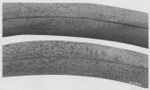 |
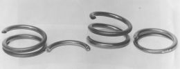
| PM04Figs. 1 and 2. Broken Exhaust Outer Valve Spring |
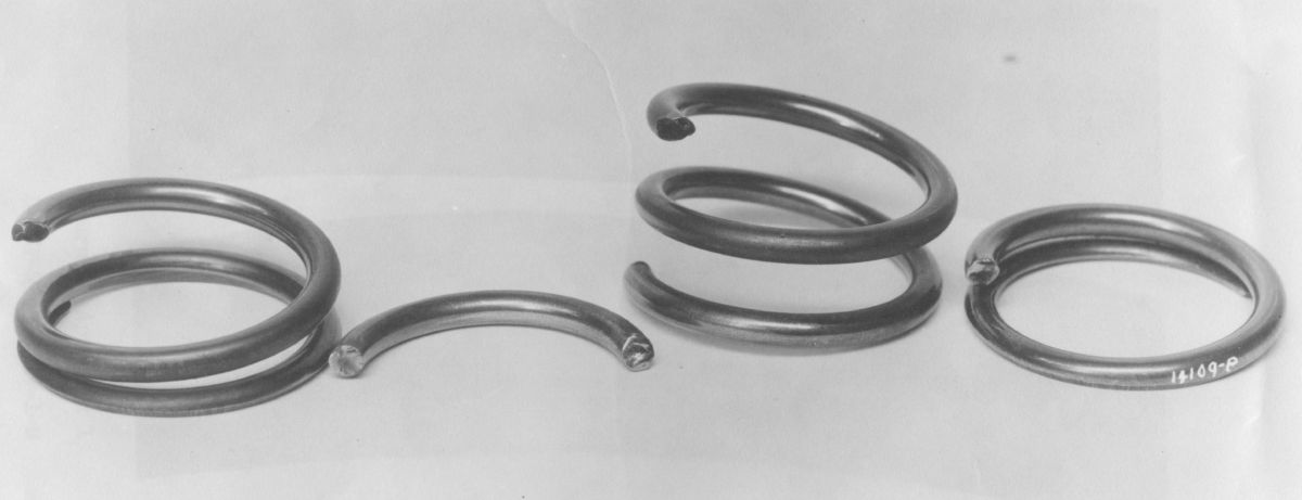
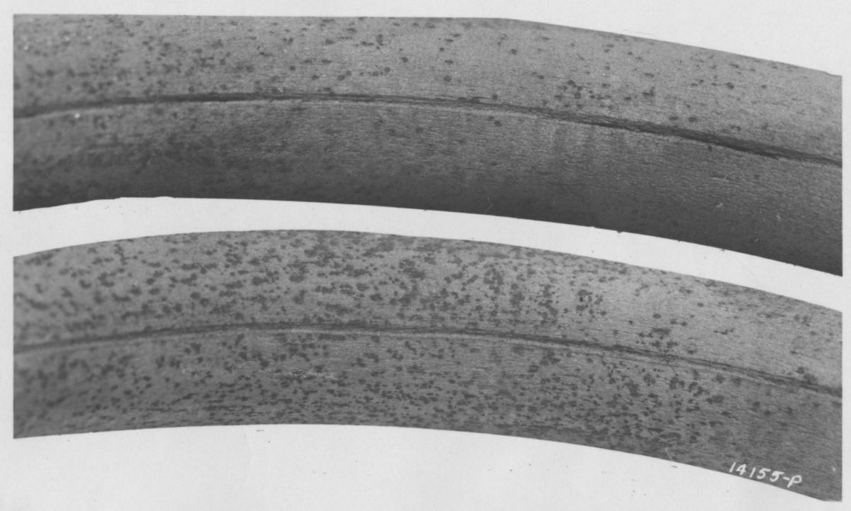
3 Apr 1942. On 12 Mar 1942, the PPL submitted a failed outer exhaust valve spring, PN 600433, for metallographic investigation. The spring, made from AMS 6450, SAE 6150 steel whose specified and actual hardness was Rockwell "C" 45, had been in service for 44 hrs 40 min and had broken into four parts (PM04Figs. 1 and 2). The fractures exhibited characteristics of fatigue failures, with the fatigue failure nuclei originating in a defect that was identified as a die mark. Deep etching in 50% hydrochloric acid revealed the defect more clearly. Microscopic examination of spring wire cross sections showed normal heat treatment structure, with no evidence of decarburization. An incipient fatigue crack was starting in a die mark indention that constituted a latent manufacturing defect and was responsible for the spring failure. This was the first unsatisfactory report written on the Packard Merlin engine series. [3 Apr 1942 Memorandum Report U-EXP-M-57-7919-1-M. Exhaust Valve Spring from Packard V-1650 Engine, A. C. #41-46533. P181015, 56 – 59.] A subsequent outer exhaust spring failure in engine AC No. 41-46533 installed in P-40F AC No. 41-13605 occurred during its accelerated service test at Patterson Field. This spring had the same fracture characteristics and the same die marks as the previous spring and had a total time of 44 hrs 40 min (44:40). Since Packard was notified and comments requested, no further action was taken except for recording the failure for reference. [16 Apr 1942 Memorandum Report U-EXP-M-57-7919-1. Failure of Outer Exhaust Valve Spring, Part No. 600433, V-1650-1 Engine, AC No. 41-46533. P181019.] AEHS contributor John Riend speculates that the defect was likely caused by the coiler feed mechanism because if it were from the drawing die, the groove would tend to wander (spiral), instead of being fairly straight. About the same time J.O. Almen, working for General Motors, came up with a standardized test method for shot peening. When Packard production dramatically ramped up to supply engines for the North American P-51, Packard instituted rigorous mechanical shot peening for inner and outer valve springs to increase the torsional endurance limit. In 1943, Packard fully standardized the Almen strip control system (invented at General Motors in 1942) across its Merlin production lines to mathematically control peening intensity. The company shifted from arbitrary "shot blasting" (surface cleaning) to strictly monitored "shot peening" (residual compression stress engineering). On 11 Aug 1945, Packard formalized these procedures into an official corporate and military-grade blueprint standard. Packard Specification PM-1470, entitled Shot Peening, outlined the exact shot size and velocity, Almen arc heights, and coverage required for final V-1650 production runs. [Correspondence with John Riend.]
9 Apr 1942. 2nd Lt Lloyd E. Kinkade reported that while Curtiss P-40F, AC No. 41-13601, engine AC No. 41-46531, was taxiing for takeoff, the entire A-bank cut out. The PN 603858 camshaft gear key had sheared. Further investigation showed that the PN 603866 camshaft and rocker shaft rear bracket bearing lock plate had also broken. The defective parts were forwarded to Packard for examination and comment since this was a new engine with only 11 hrs total time. Lt Kinkade concluded that the camshaft and rear bracket bearing lock plate failed first, permitting the PN 603813 camshaft rear bushing to rotate and shut off the oil supply to the camshaft causing the camshaft bearing to seize and shear the camshaft gear key. He further concluded that the lock plate was a defective stamping, which resulted in fatigue failure. Since this was the first failure of its kind, Lt Kinkade recommended that no further action be taken except for recording it for future reference. [9 Apr 1942 Memorandum Report U-EXP-M-57-8015. Failure of Camshaft and Rocker Shaft Rear Bracket Bearing Lock Plate, Part No. 603866, C-1650-1 Engine, Air Corps No. 41-46531. P172065.]
10 Apr 1942. Packard Chief Test Engineer R.N. DuBois sent the PPL three copies of "Investigation of Merlin 61 Engine No. A-9," Serial No. 41, dated 7 Apr 1942. Only the cover letter exists; no report copies were found. [Letter. 65.]
17 Apr 1942. Maj A.F. Wentzel, Chief, Technical Control Branch, Inspection Section, wrote the Army Air Forces (AAF) Resident Representative at Packard, advising that a power calibration check upon completion of the V-1650-1 Model Test would be required. [Letter, 69.]
18 Apr 1942. DuBois sent the Production Engineering Section three copies of Packard Report No. 39, "Inspection Report of Piston Rings Tested on Merlin 28 engine A-1 from 285:52 to 669:15 Hours," dated 25 Mar 1942. Unfortunately, we only have the cover letter, not the reports. [Letter. 70.]
18 Apr 1942. In a 27 Mar 1942 letter, Packard stated that valve cover hold-down studs were failing because overhaul personnel were using improper tools; the special tools designed for this work were not available. [Cross Reference No. 452.8 – Packard Merlin V-1650 Engine. 71.]
21 Apr 1942. In view of a critical nickel shortage, the War Production Board questioned the necessity for nickel in Packard-built Merlin crankcases. The question was discussed with the PPL, Aeronautical Equipment Branch of the Production Engineering Section and the Experimental Engineering Section Materials Laboratory. All agreed that crankcases for test would be ordered made from ALCOA's #355 alloy, which was used in the Allison crankcase and that any change would be based on the results of those tests. The test program was being expedited at Packard and the Specification Branch would be kept informed as to progress. [Cross Reference No. 410.2 Nickel; 452.8 Rolls-Royce Merlin-Packard Built. 73.]
22 Apr 1942. PPL carburetor specialist Roy E. Hoffman commented on the carburetor setting data furnished in the 8 Apr 1942 Bendix Products Division letter, which was forwarded with Drawing and Data Transmission Report No. G-42-392 dated 9 Apr 1942. The PD-16A1 carburetor data, in accordance with Parts List 392224-10, were in agreement with the previous data submitted by Packard and were identical with the carburetor setting that proved satisfactory in flight tests and, therefore, were satisfactory. No information was available on the PD-16B1 carburetor since this was for British procured engines and was not to Air Corps specifications. Hoffman recommended that Packard be given a release on the V-1650-1 carburetor setting in accordance with Air Corps Setting No. 401 and Parts List 392224-10. [22 Apr 1942 Memorandum Report EXP-M-57-519-66. Carburetor Setting Data on V-1650-1 Engine. P153260.]
24 Apr 1942. Curtiss-Wright had returned presumably defective V-1650-1 AC 41-46577, Mfg. No. A-170, to Packard. Standard procedure had been to receive the engine, correct faults and reship it immediately to the point from which it had been received. It had NOT been Packard's custom to forward replacement engines because Packard was regularly shipping new production engines and C-W could simply install another engine before shipping the airplane. Packard wanted to know if there was any deviation from its standard procedure. [Cross Reference No. 452.8 Packard 1650 Engine. 75.]
25 Apr 1942. Air Force Section informed the Experimental Engineering Chief that exhaust stack covers designed for Bell P-39 and Curtiss P-40 series airplanes would also fit P-40F airplanes. A new carburetor air intake cover was being designed for P-40F airplanes. [Cross Reference No. 452.1 P-40 Airplane; 452.8 Packard V-1650-1 Engine. 76.]
25 Apr 1942. PPL civilian engineer Ford L. Prescott visited Packard to investigate V-1650-1 combustion gas leakage, which he concluded resulted from the soft aluminum head gaskets creeping and the austenitic steel hold-down studs stretching. He recommended using the latest R-R construction be adapted.
Two test engines were examined and considerable compression leakage noted at the head gaskets. The cylinder block construction incorporated a flange at the cylinder sleeve upper end that was held between two aluminum gaskets. The upper gasket was completely constrained by the counterbore in the cylinder block and a spigot on the cylinder head; this gasket was about 0.063" thick and 0.312" wide. Under the cylinder flange was a second gasket about 0.250" wide, which was cut away on its inside for a rubber sealing ring and overhung the flange by approximately 0.063", leaving and annular gasket portion in direct compression that was about 0.063" wide. These rings showed excessive printing in due to the cylinder flange pressure. The compression leakage occurred at the upper gasket and the appearance was that the lower gasket had yielded enough to loosen the upper gasket crush, thereby permitting combustion gas blowby.
The long austenitic steel cylinder head studs had a high thermal expansion coefficient, which was to prevent their overstressing due to the differential cylinder jacket and stud thermal expansion when the engine was operated. The austenitic stress-strain proportional limit was about 80,000 psi, but Prescott suspected poor creep characteristics that would cause the studs to assume a permanent stretch at elevated temperature when loading did not exceed 80,000 psi. Laboratory examination found a permanent 0.008" set after only a green run. Further examination of loosening torques disclosed that the end studs did not yield appreciably while some studs in the block middle lost considerable preload. A new stud design proposed by R-R used high strength alloy steel with a 175,000 psi proportional limit. These studs were reduced in diameter in order to decrease differential expansion by decreasing the stud's spring constant. R-R proposed modifying the cylinder jacket to eliminate the aluminum gasket between the cylinder flange and jacket. Unfortunately, this meant scrapping all the cylinder blocks and cylinder liners on hand. Prescott suggested adopting the new stud design and replacing the highly loaded aluminum gasket between the cylinder flange and jacket with a harder, perhaps steel, gasket. This would eliminate the preload loss while still using the present jackets and cylinders. Vincent suggested that accelerated warm-up/cool-off cycle tests be run on two engines, one with the current gasket and stud design, and the other with the new scheme in one bank and the other bank unchanged from then-current practice. These engines were to be subjected to 25 15-min cycles, during which the engine would be started, brought to temperature, cooled down and stopped, simulating the heating and cooling during takeoff and landing. Packard would send the results of this accelerated heat cycle test to MatCmd as a basis for deciding a remedy to the unsatisfactory design. [2 May 1942 Memorandum Report EXP-M-57-503-601. Packard V-1650-1 Engine. P192546.]
30 Apr 1942. MatCmd directed Hamilton Standard to ship Packard a complete propeller assembly so that blade vibration tests could be run. MatCmd requested copies of the test results. [Cross Reference 452.8 Packard-Merlin Engine; 452.025 Propellers, General. 78.]
30 Apr 1942. The Aircraft Laboratory Chief had ordered a study of installing Rolls-Royce Merlin 61 engines in the Lockheed P-38E, Bell XP-39E, and Curtiss P-40F Airplanes. The study concluded the following for the P-38E with Merlin 61 engines:
a. High speed would increase from 390 mph to 440 mph.
b. The design gross weight would increase from 14,424 lb to 14,700 lb.
c. The engine could be installed with minimum structural changes; ultimate flight load would be reduced from 12.0 g to 11.7g.
d. The engine change would necessitate the addition of ballast or a redesign to obtain a satisfactory CG location; balance with the Merlin 61 would be too far forward for satisfactory flying qualities. (Note: One can surmise the installation involved removing the turbosuperchargers and associated ducting and heat exchangers, most of which was behind the CG.)
The XP-39E study concluded that:
a. High speed would increase from 390 mph to 409 mph; service ceiling would increase from 32,000 ft to 34,500 ft.
b. Gross weight would increase from 9,083 lb to 9,290 lb.
c. Merlin 61 installation would require a major fuselage redesign. With an ultimate load factor of 12.0 g at the design gross weight of 8,722 lb the wing supported 120% of ultimate load during static tests. This would give an ultimate load factor of 14.4 g at design gross weight for 100% ultimate load on the wings. For a gross weight increase from 9,083 lb to 9,230 lb the ultimate wing load factor would be reduced from 13.8 g to 13.6 g.
d. Satisfactory flying characteristics were expected with a slight stabilizer decalage change or weight distribution to move the CG further aft.
he P-40E study concluded that:
a. High speed would increase from 370 mph to 389 mph; service ceiling would increase from 32,000 ft to 35,500 ft.
b. Gross weight would increase from 8,267 lb to 8,846 lb.
c. Engine installation could be accomplished with minimal structural revision. The ultimate flight load factor would be reduced from 12.3 g to 11.5 g.
d. Ballast would be required for satisfactory flying characteristics during testing. A stabilizer decalage adjustment or weight redistribution for a more aft CG location would accomplish the desired result in production aircraft.
The studies concluded that Merlin 61 installation in the Curtiss P-40F was the most feasible for test purposes; load factors were considered satisfactory for that purpose.
Merlin 61 Installation Study Appendix 1
Table PM04 I. Lockheed P-38E Weight & Balance
| Item | Allison V-1710-27 & -29 | Rolls-Royce Merlin 61 |
|---|
| Wing Group | | 1,925 | | 1,925 |
| Tail Group | | 408 | | 408 |
| Body Group | | 1,450 | | 1,460 |
| Alighting Gear | | 822 | | 822 |
| Nacelle Group | | 446 | | 465 |
| Power Plant Group | | 5,647 | | 5,904 |
| Engines | 2,610 | | 3,300 | |
| Engine Accessories | 349 | | 318* | |
| Power Plant Controls | 75 | | 71 | |
| Propellers and Spinners | 684 | | 698 | |
| Starting System | 82 | | 11** | |
| Supercharger System | 295 | | 0 | |
| Cooling System | 901 | | 855 | |
| Lubricating System | 115 | | 116 | |
| Fuel System | 535 | | 535 | |
| Fixed Equipment Group*** | | 1,172 | | 1,172 |
| Armor Plate and B.P. Glass | | 250 | | 250 |
| Empty Weight | | 12,130 | | 12,406 |
| Crew (1) | 200 | | 200 | |
| Fuel (230 gallons) | 1,380 | | 1,380 | |
| Oil (17 gallons) | 128 | | 128 | |
| Armament | 826 | | 826 | |
| Equipment | 10 | | 10 | |
| Useful Load | | 2,544 | | 2,544 |
| Gross Weight | | 14,672 | | 14,950 |
Design Gross Weight
(less Armor Plate and
B.P. Glass at 250 lb) | | 14,424 | | 14,700 |
| Balance (% MAC) | | 27.5% | | 23.5% |
| * Includes cooling system weight for liquid-cooled aftercooler. |
| ** Starter weight included in engine weight. |
| *** Includes camouflage paint at 27 lb. |
Table PM04 II. Lockheed P-38E Performance
| Engines (2) | Allison V-1710-27 and -29 | Rolls-Royce Merlin 61 |
|---|
| Normal Rating (hp/alt) | 1,000/25,000 | 1,240/16,750; 1,080/27,750 |
| Military Rating | 1,150/25,000 | 1,500/13,000; 1,300/24,000 |
| Takeoff Rating | 1,150/Sea Level | 1,300/Sea Level |
| Gross Weight (lb) | 14,424 | 14,700 |
| Wing Loading (lb/ft²) | 44.0 | 44.8 |
| Power Loading (lb/TO bhp) | 6.28 | 5.65 |
| High Speed (mph/alt) | 390/20,000 | 440/24,000 |
| Range, 75% Normal* (mi/alt) | 660/20,000 | 680/27,750 |
| Speed, 75% Normal (mph/alt) | 340/20,000 | 400/27,750 |
| Time to 20,000 ft** (min) | 7.21 | 6.70 |
| Takeoff Over 50ft Obstacle (ft) | 1,800 | 1,750 |
| Ultimate Load Factors | | |
| Flight (g) | 12.0 | 11.7 |
| Landing (g) | 7.0 | 6.8 |
| *Range with 290 gal Fuel |
| **Climb at Normal Power |
Table PM04 III. Bell XP-39E Weight & Balance
| Item | Allison V-1710-47 | Rolls-Royce Merlin 61 |
|---|
| Wing Group | | 1,071 | | 1,071 |
| Tail Group | | 153 | | 153 |
| Body Group | | 719 | | 760 |
| Alighting Gear | | 773 | | 773 |
| Power Plant Group | | 3,103 | | 3,209 |
| Engine* | 1,645 | | 1,725 | |
| Engine Accessories | 230 | | 190** | |
| Power Plant Controls | 25 | | 25 | |
| Propeller | 361 | | 471 | |
| Starting System | 41 | | 8*** | |
| Cooling System | 323 | | 312 | |
| Lubricating System | 68 | | 68 | |
| Fuel System | 410 | | 410 | |
| Fixed Equipment Group | | 1,117 | | 1,117 |
| Empty Weight | | 6,936 | | 7,083 |
| Crew (1) | 160 | | 160 | |
| Fuel (100 gallons) | 600 | | 600 | |
| Oil (11.3 gallons) | 85 | | 85 | |
| Armament | 1,302 | | 1,302 | |
| Useful Load | | 2,147 | | 2,147 |
| Gross Weight | | 9,083 | | 9,230 |
| Balance (Wheels Up) | | 25.9% MAC | | 24.0% MAC |
| * Includes extension shafting, bearings and remote gearbox. |
| ** Includes cooling system weight for liquid-cooled aftercooler. |
| *** Starter weight included in engine weight. |
Table PM04 IV. Bell XP-39E Performance
| Engine | Allison V-1710-47 | Rolls-Royce Merlin 61 |
|---|
| Normal Rating (hp/alt) | 1,000/22,000 | 1,240/16,750; 1,080/27,750 |
| Military Rating | 1,150/24,000 | 1,500/13,000; 1,300/24,000 |
| Takeoff Rating | 1,325/Sea Level | 1,300/Sea Level |
| Gross Weight (lb) | 9,083 | 9,230 |
| Wing Loading (lb/ft²) | 38.5 | 39.1 |
| Power Loading (lb/TO bhp) | 6.85 | 7.1 |
| High Speed at Critical Altitude (mph/alt) | 390/24,000 | 409/24,000 |
| Endurance at 100% Normal* (hr/alt) | 1.3/22,000 | 1.4/27,750 |
| Speed at 100% Normal (mph) | 360 | 394 |
| Time to 24,000 ft** (min) | 13.5 | 12.8 |
| Service Ceiling (ft) | 32,000 | 34,500 |
| Takeoff Within (ft) | 3,000 | 1,800 |
| Ultimate Load Factors | | |
| Flight (g) | 13.8 | 13.6 |
| Landing (g) | 7.0 | 6.9 |
| *Endurance with 150 gallons Fuel |
| **Climb on Military Power |
| *** Takeoff distance to clear 50-ft obstacle estimated to be 1,750 ft with Allison engine, 1,800 ft with Rolls-Royce engine. |
Table PM04 V. Curtiss P-40E Weight & Balance
| Item | Packard V-1650-1 | Rolls-Royce Merlin 61 |
|---|
| Wing Group | | 1,080 | | 1,080 |
| Tail Group | | 125 | | 125 |
| Body Group | | 1,156 | | 1,170 |
| Fuselage | 461 | | 475 | |
| Alighting Gear | 695 | | 695 | |
| Engine Section | | 309 | | 332 |
| Power Plant Group | | 2,746 | | 3,206 |
| Engine | 1,461 | | 1,650 | |
| Engine Accessories | 116 | | 185* | |
| Power Plant Controls | 22 | | 24 | |
| Propeller | 352 | | 526 | |
| Starting System** | 6 | | 8 | |
| Cooling System | 301 | | 301 | |
| Lubricating System | 56 | | 80 | |
| Fuel System | 432 | | 432 | |
| Fixed Equipment Group*** | | 774 | | 774 |
| Empty Weight | | 6,190 | | 6,687 |
| Crew (1) | 180 | | 180 | |
| Fuel (146 gallons) | 876 | | 876 | |
| Oil (16 gallons) | 120 | | 120 | |
| Armament | 901 | | 901 | |
| Useful Load | | 2,077 | | 2,189 |
| Gross Weight | | 8,267 | | 8,846 |
| Balance | | 25.7% MAC | | 24.0% MAC |
| * Includes cooling system weight for liquid-cooled aftercooler. |
| ** Starter weight included in engine weight. |
| *** Includes 134 lb armor plate. |
Table PM04 VI. Curtiss P-40E Performance
| Engine | Packard V-1650-1 | Rolls-Royce Merlin 61 |
|---|
| Maximum Cruising Rating (hp/alt) | 1,000/Sea Level; 1,092/10,000; 1,010/16,000 | — ; 1,240/16,750; 1,080/27,750 |
| Continuous Climb Rating | 1,137/Sea Level; 1,225/10,000; 1,143/17,000 | — ; — ; — |
| Military Rating | 1,130/Sea Level; 1,240/11,800; 1,122/19,000 | — ;1,500/13,000; 1,300/24,000 |
| Takeoff Rating | 1,300/Sea Level | 1,300/Sea Level |
| Gross Weight (lb) | 8,267 | 8,846 |
| Wing Loading (lb/ft²) | 35.0 | 37.5 |
| Power Loading (lb/TO bhp) | 6.36 | 6.81 |
| High Speed at Critical Altitude (mph/alt) | 370/22,000** | 389/27,000** |
| Operating Speed at 45% Cruise (mph/alt) | 235/15,000 | 255/26,000 |
| Range at Operating Speed (mi) | 950 | 950 |
| Time to 15,000 ft (min) | 6.9 | 6.2 |
| Service Ceiling (ft) | 32,000 | 35,500 |
| Takeoff Distance (ft) | 2,300 | 2,600 |
| Ultimate Load Factors | | |
| Flight (g) | 12.3 | 11.5 |
| Landing (g) | 7.2 | 6.7 |
| *Engine ratings from Curtiss Specification 7437A. |
| **3,000 ft effective ram. |
Discussion
Merlin 61 installation in the Lockheed P-38E could have been accomplished without major change to the basic airplane structure. The engine cowl would have required revision to accommodate the new installation. A redesigned engine mount would have been provided and the engine compartment cooling ducts would have been rearranged. The turbosupercharger installation would have been removed and the aftercooler radiator located in the current turbosupercharger location. The exhaust system would have been replaced by an ejector stack system with a possible gain at high speed not considered in the performance estimate. The cooling system would have been retained except that the pure glycol would have been replaced with a glycol-water cooling medium. Lack of exact Merlin 61 cooling requirements prohibited a more detailed cooling investigation. Three-blade 11' 6" propellers would have been suitable. Four-blade propellers were prohibited because of aircraft CG considerations. The useful load was retained and the gross weight increased by the new engine installation, leading to a load factor reduction. Balance at the increased weight was unsatisfactory with the new CG location being substantially ahead of the original. Landing trim would be impossible unless the CG were moved aft. Ballast for test purposes may be satisfactory, but for production a change in stabilizer decalage or equipment relocation would have been necessary to give satisfactory landing control. The Table PM04 II performance summary indicates improved high speed, but the increased weight and turbocharger removal may have lowered the service ceiling.
Merlin installation in the Bell XP-39E would require revision to the basic fuselage and wing structures. This airplane was already equipped with a radiator for the liquid-cooled aftercooler. However, the revised engine installation would require cooling system relocation. Radiators were assumed to be satisfactory in the absence for specific Merlin 61 cooling requirements. The gross weight would have increased resulting in a load factor reduction. The original armament and useful load were maintained for military utility. Balance at the new gross weight was expected to be satisfactory for stability and control. Flight tests would be required for a more accurate stability and control check. Modification similar to those discussed for the P-40F might have been necessary. A 11' 6" four-bladed propeller would have replaced the existing propeller. High speed, range and service ceiling would have been improved.
Merlin 61 installation in the Curtiss P-40F could be made without major structural revision. An enlarged cowl and larger engine mount were required. The cooling system was to be retained and a radiator for the liquid-cooled aftercooler was to be added. Armament and useful load were retained. The gross weight increased reduced the load factors. An 11' 2" four-blade propeller was considered suitable. Balance at the increased gross weight was slightly forward to the original CG location. For experimental test, ballast in the tail was expected to be satisfactory. Production models a decrease of about 2° in stabilizer incidence was expected to give satisfactory landing control. Stick forces with the forward CG could be reduced by an elevator balance increase or balance tab usage. Improved high speed and service ceiling was expected. [30 Apr 1942 Memorandum Report EXP-M-51/AG134. Installation of Rolls-Royce Merlin 61 Engine in Lockheed P-38E, Bell XP-39E, and Curtiss P-40F Airplanes. 80 - 93.]
1 May 1942. Col Carroll wrote DeBois at Packard complaining that the historical record, Form No. 60B, for the V-1650-3 engine had not been sent to MatCmd along with the engine the last time the engine was sent to Dayton for testing. Col Carroll requested that this for be brought up to date and space left for MatCmd to insert a record of the engine during the last running at MatCmd. Col Carroll also requested that this form be sent along with the engine when it was next sent to MatCmd for testing. [Letter, Col Carroll to Packard. V-1650-3 Engine Form No. 60B. 95.]
2 May 1942. It had come to the attention of Production Division that Packard was not delivering maintenance parts concurrent with R-R engines. The Air Service Command said it was impossible to supply the various Air Force Activities for the P-40F airplanes. Air Service Command directed that this matter be investigated and a report rendered as to why Packard could not deliver spare parts concurrent with its engine deliveries. [Telegram E-476. 97.]
4 May 1942. Requisition For Distribution Allocation (RFDA) codes were used during the USAAF procurement process to track specific supply blocks and contract allocations to British/Commonwealth air arms under Lend-Lease. Capt David B. Makepeace, writing for United Nations Section Chief Col C.P. Kane, notified the Wright Field Production Division Chief that no Authority for Purchase had been issued covering the 1 May 1942 British Air Commission memorandum for Requisitions RFDA 8967 and RFDA 9902 for 14,000 Packard Merlin 28 engines. Contract Section advised the Production Engineering Section Chief that a conference with Packard had tentatively been scheduled for 12 May 1942. At that time, British Packard Merlin engines had no further designations other than Merlin 28, Merlin 29, and Merlin 31. For example, Merlin 28s were being built with either 12V or 24V electrical systems, depending on installation. Contracts Section wanted clarification as to the specifics of the Packard Merlins being ordered under these RFDAs. On 5 May, Col O.R. Cook, the Production Engineering Section Chief, asked the Aeronautical Equipment Branch of the Production Engineering Section what progress had been made with this contract. [Letters, 98, 105.]
6 May 1942. Production Engineering Section Chief Col O.R. Cook complained that considerable V-1650-1 spark plug fouling had occurred in P-40F and L airplanes with improper carburetor settings that were idling at low rpm. In order to assure that sufficient service replacement spark plugs were available, an extra plug set was requested above the two sets then furnished with the engine as part of the miscellaneous tools and equipment then furnished. [Letter, Col Cook to Leon, Wright Field Service Command (Unit J). 101.]
8 May 1942. Packard Merlin Type 29 engines for the Canadian Government were to be supplied with the following Packard Parts: 605320 Screw, 605328 Lockplate, 605328 Bolt, 605329 Nut, E-29766/1 Body, Control Mixture, Control Link Ball Joint [Telegram PE-523. Production Section. 104.]
11 May 1942. Writing for Contract Section Chief Col A.E. Jones, H.N. Searles informed the Experimental Engineering Section Chief that the matter of V-1650-3 improvements had been temporarily tabled until funds became available to support such an activity. Later, funds for coolant pump improvements had became available, an Authority for Purchase was originated, and Vincent was notified on 18 May 1942. [IOM, 1st Indorsement, Searles to Experimental Engineering Section Chief. 109 – 110.]
12 May 1942. When V-1650-1 AAF No. 41-46673 was installed P-40F, AAF No. 41-13606, and fired, oil began leaking from the fuel pump drain. The pump was removed, disassembled, and the PN 605713 fuel pump drive shaft seal was found missing. This had apparently been omitted when the engine was assembled and its absence was not detected during the engine acceptance run. Col Cook requested an investigation to ensure similar omissions did not occur. [Letter, Col O.R. Cook to Packard. 112.]
13 May 1942. Col Carroll informed Field Services Headquarters that recalibration work on the V-1650-1 war emergency valves was necessary. The AAF planned to replace all these valves when improved valves became available. In the meantime, these controls were to be sealed in the automatic boost position and pilots cautioned not to break the seal as severe detonation due to excessive manifold pressure might ruin the engines. [Letter, Col Carroll to Field Services Headquarters. 113.]
15 May 1942. Restricted Project No. MX-252, titled "Installation Studies of Rolls-Royce Merlin Engine (Packard V-1650-3) in Service Airplanes" was assigned. This classification was cancelled on 1 Oct 1945. [Cross Reference, Letter, IOM. 114 – 117.]
16 – 19 May 1942. 2nd Lt L.E. Kinkade visited Morris Field, North Carolina to investigate V-1650-1 engines with fouled spark plugs, oil in the boost control aneroid chamber, and clogged carburetor impact tubes, all blamed on supercharger volute drains. He concluded that the drains had no effect on the fouled plugs, oil in the boost control or excessive oil consumption. He did suspect it added to the clogged carburetor impact tubes. Since MatCmd had given Packard permission to plug the volute drain, he recommended that this be done.
The PPL had given Morris Field permission to cut the volute drain line on one airplane. The carburetor end was crimped shut and the supercharger line routed overboard. A 25-hr service test was planned for this airplane. After several flight hours the airplane operation was satisfactory except that a mixture of raw gasoline and oil was coming from the open volute drain and covering the airplane belly, creating a fire hazard. On 17 May 1942, after approximately 10 hrs service testing, the pilot overshot the field, damaged the airplane, thus ending the test. During the test the oil consumption dropped from 32 qt in 6 hrs before venting the volute to 12 qt in 5 hrs after the drain was vented. Since the volute drain presumably had no bearing on oil consumption, the oil consumption changes must have been from another source. This particular engine had been subject to oil consumption changes.
Three airplanes had been grounded because of excessive oil in the boost control aneroid chamber. This was discussed with the squadron engineers and Packard representatives. One of the grounded planes was flown for more than two hours and reported to be operating normally. The boost control and manifold were inspected and a normal amount of oil found in each.
Prior to Lt Kinkade's visit, squadron engineers reported that the carburetors removed due to lean mixtures had clogged impact tubes. They theorized that when the engine was stopped oil drained from the supercharger tail shaft bearing down into the air scoop, forming sludge as it mixed with any dust in the scoop. This sludge was then thrown up into the carburetor impact tubes when the engine started. The air scoops on two airplanes were inspected and no oil traces found. There also was no evidence of lean mixture, but Packard had reported a similar condition during dynamometer testing.
Squadron engineers believed that the volute drain was throwing oil into the induction system causing it to build up in the intake manifold to the extent it fouled spark plugs; they thought if the volute drain were vented overboard it would remove enough oil from the induction system to stop plug fouling. The airplane that carried out this test was reported to be operating satisfactorily. The plugs from a rough-running engine were inspected and no indication of oil fouling observed. Experience had shown that any of the following conditions might cause plug fouling
a. Overpriming the engine when starting.
b. Extended idling at low rpm.
c. Excessive time for conducting a magneto check.
[25 May 1942 Memorandum Report U-EXP-M-57-8170-1. Fouling of Spark Plugs, Boost Control Aneroid Chamber Full of Oil, Carburetor Impact Tubes Clogged on V-1650-1 Engines. P171178, 122 – 124.] On 3 Jun 1942, Col Cook (?) requested that Technical Instructions be sent to operating units advising them that sluggish boost control operation might be fixed by lubrication every 50 hrs with machine gun oil or whenever the control seemed sluggish. [Cross Reference Contract Files AC-15082. 135.]
19 May 1942. Brig Gen K.B. Wolfe, Chief, Production Division wired the Packard AAF Representative and Central Procurement District Supervisor, again complaining that Packard was not delivering sufficient maintenance spares with its engine deliveries. He demanded to know what action was being taken to address this. [Teletype PES-630. 119]
26 May 1942. Col Carroll requested that a Technical Order be issued directing the rework of all V-1650-1 engines in accordance with instructions on Packard's layout drawing No. 609, dated 19 May 1942, "Reduction Gear Propeller Shaft Oil Drain." [IOM, Col Carroll to Air Service Command. 125.]
27 May 1942. Col Carroll notified the Air Service Command that PN 393160 Carburetor Intake Flange Studs were loosening and coming out of V-1650-1 engines in service. Packard was aware of this and had provided layout drawing No. 590, which showed a method of correcting this. The proposed changes were being rushed through testing. Col Carroll suggested that until the unsatisfactory condition was fully addressed that all stations were to drill a No. 65 hole 1 – 2 threads from the end and the nuts and studs be safety-wired with 0.025" steel wire. [IOM, Col Carroll to Air Service Command Chief, Wright Field. 127.]
1 Jun 1942. Morris Field, North Carolina, had wired MatCmd about numerous engine failures in P-40, P-40G and P-40F airplanes. Lt Col Whitney, Capt Couplane, and Lt Moore of the Air Service Command and Messrs. Brown and Beaman visited Morris field to investigate. They concluded that the sandy conditions were bad but not as severe as the conditions at Florence and Wilmington, North Carolina. Except for the possibility of sand mixing with oil and affecting the V-1650-1 carburetor metering characteristics in P-40F airplanes, this was not thought to be a primary factory in the engine difficulties at Morris Field. Only anecdotal information was available about the V-1650-1 engine cut-outs and practically no data was available on the Allison V-1710 difficulties. The MatCmd personnel recommended that the two V-1650-1 engines, AF Nos. 41-46698 and 41-46633 be forwarded to Wright Field. Fuel samples, along with new and used oil samples were obtained and returned to Wright Field. The MatCmd personnel recommended that P-40 airplanes at Morris Field be released for flight unless further unsatisfactory conditions were identified during the ongoing 100-hr inspection.
Amplification: Morris Feld had reported numerous engine difficulties, failures and forced landings, including two fatalities. The Field had previously been visited by the regional director of a newly-established Safety Organization. All P-40 type airplanes had been grounded and when MatCmd personnel arrived, ground personnel were engaged in 100-hr inspections of all airplanes. The Commanding Officer, Group Engineering Officer and various flight and ground personnel were contacted regarding the difficulties, servicing procedures and operating conditions.
Morris Field airplanes were operating under adverse sand conditions with red and gray clay natural soil, which was probably not as abrasive as the dry fine silica sand at Wilmington and Florence. The runways and aprons in front of Operations and the hangars were paved with a very inferior concrete grade. While this surface was rather hard, there was much concrete and clay dust. MatCmd personnel took a dust sample and returned it to Wright Field for further analysis.
The Morris Field group operated mainly P-40, P-40G and P-40F aircraft, with a few P-40E, P-40E-1 and P-43 airplanes. The Field was a training center for about 90 trainees, who would accumulate about 100 hrs flying time in three months; the trainee number was expected to soon increase to 180. Several pilots considered the P-40E superior to the Allison V-1710-33-equipped P-40 aircraft, which were referred to as "clunkers." These aircraft were high-time and considerable maintenance work was required to modify them in accordance with Technical Orders due to repairs and replacement of worn parts. The pilots considered the Packard engine generally less likely to sputter and miss during takeoff than the Allison. This was probably due to the Packard boost control that prevented overboosting. However, the Allison engine acceleration was considered superior, probably because the Packard's automatic boost control lagged in response to cockpit throttle motion; this made the P-40F difficult to operate in close flight formation, which required continual throttle adjustment. Pilots reported more engine problems and more maintenance on the Packard engines.
Packard V-1650-1 Engine Failures and Difficulties:
1) MatCmd personnel obtained data about a forced landing in a P-40F, AF No. 41-13664 with AF No. 41-46698 engine, which had 107:20 hrs when the 1 Jun 1942 forced landing occurred.
a) MatCmd personnel contacted Lt Champion, the pilot, and obtained a rather concise and accurate story of the engine malfunction. The airplane was in a 30° climbing right turn at 8,500 ft when a momentary combined miss and rough engine operation occurred. He leveled off and descended to about 4,000 ft while maintaining cruising conditions of about 2,450 rpm and 33 inHgA. The intermittent missing and rough operation continued until about 1,600 ft when Lt Champion called the tower and advised that he was attempting an emergency forced landing. Just prior to landing the pilot advanced the propeller control and obtained about 2,700 rpm with very slight propeller control motion. He retarded the throttle to approximately 20 inHgA manifold pressure and the engine became extremely rough. He then advanced the throttle; the roughness continued but was not as severe as before. Lt Champion observed the engine instruments, which all seemed to indicate properly. The coolant temperature started to fall just below 90°C and Lt Champion closed the coolant radiator shutter slightly. The mixture control was in the Auto-Rich position and the automatic boost control was in the ON position. The engine speed increase to 2,700 rpm and the throttle motion to correct the roughness caused the pilot to overshoot the field in an attempted landing. He decided to go around for another landing attempt, but the engine started loosing power. He moved the boost control to OFF, but this produced no change in engine operation. The engine then cut out completely and the airplane landed among some pine trees; after hitting a tree the airplane nose entered a clearing beyond the trees.
b) MatCmd personnel inspected the airplane and found that despite wing, undercarriage and radiator damage, the engine appeared to be in generally intact. There was still fuel in the three tanks. The carburetor was removed and the strainer checked; a slight amount of dirt was found but other than slight damage to the mounting studs and carburetor flange, the carburetor appeared to be in good condition. One venturi and choke was removed to determine if the openings were clogged, but they were all free and clear. The magneto ignition leads appeared to be in good condition.
c) MatCmd suggested that the engine including all accessories and the entire fuel system including the fuel selector valve, booster pump, vapor eliminator, engine driven fuel pump and pressure control valve connected to the vapor eliminator be forwarded to Wright Field for further investigation.
2) The emergency landing of P-40F with V-1650-1 engine AF No. 41-46633 resulted in the pilot being fatally injury. Very little date could be obtained as there were few witnesses. Available data indicated that the pilot attempted a forced landing with a dead engine in a small nearby private flying field. The right landing gear was locked in the extended position but the left gear was retracted. The pilot evidently made a sharp turn to the field, which resulted in the airplane rolling over onto its back. The engine was severely damaged. MatCmd suggested that the engine also be forwarded to Wright Field where the possibility of internal engine damage might explain the engine failure.
3. General V-1650-1 Maintenance Difficulties
a) Morris Field technical personnel complained that supercharger volute and intake manifold drain plumbing, which were connected together at the carburetor, deposited excessive quantities of oil in and around the venturis and chokes, affecting metering characteristics. Packard had verified this and established that the danger of loading the supercharger volute was remote. A technical order had been issued to plug the volute drain, but had not been accomplished on all Morris Field aircraft.
b) Coolant pump replacement was necessary about every 50 hrs and sometimes coolant leaks resulted. This was caused by an unsatisfactory coolant pump shaft packing. Packard was experimenting with a new packing that was to alleviate the condition.
c) Carburetor mounting studs were failing in the threads and passing into the supercharger. A technical order had been issued calling for drilling and safety-wiring the studs, which prevented broken studs from entering the induction system. This was being investigated further as the air scoop had interference points on the engine cowling that put excessive strain no the carburetor studs.
d) Propeller shaft seal leaks had been experienced in reworked nose sections, which were supposed to allow oil to drain away into the dual drive. This was successful with the new propeller shaft seal; the old seal was more satisfactory as the new one, but the higher spring tension, tended to wear unevenly.
e) Frequent spark plug fouling required frequent plug removal and reconditioning. A Denison spark plug cleaner was available, but there were no instructions and the machine had not been set up for use in checking and reconditioning spark plugs. MatCmd personnel removed a plug set and examined them. They appeared to be in good operating condition. Brown advised what warm-up should be done at 600 – 800 rpm as once the plugs fouled it was very difficult to clear them. A hotter plug might be required for the engine.
f) Excessive oil in the induction system and around the backfire screens had been noted. This was a side effect of lubricating the supercharger shaft tail plain bearing. This large oil quantity was probably a major factor in fouling spark plugs during warm-up when part-throttle caused a high vacuum and considerable oil leakage from the tail bearing.
g) Prestone tank failures had occurred, and while this was not an engine issue, tank cracking had occurred around the boss that supported the pop-off valve and around the bosses to which the cylinder block outlet lines connected.
4. Allison V-1710 Failures and Difficulties
a) A P-40 crash that resulted in a fatality had recently occurred but details were not available. It was determined that the engine had been equipped with the new sodium-cooled intake valves.
b) A V-1710-33 engine, AF No. 40-106 in P-40E-1, AF No. 41-24991, had been overhauled at about 200 hrs time on 28 Dec 1941 at Fairfield Air Depot. Since that overhaul, the engine had run only 7.5 hrs. A large quantity of gummy or rubbery material had been discovered in the automatic Cuno oil filter. Morris Field personnel thought that it may have been a gasket or grommet getting into the lubrication system. An oil sample was taken and submitted to a local school for analysis that revealed the oil had been contaminated with sugar. Another oil sample was collected and sent to Wright Field for further physical and chemical analysis. MatCmd personnel pointed out that the foreign material may have been engine preservative that had not been completely removed. Similar conditions had been observed by MatCmd during Allison block test runs.
c) Morris Field V-1710-33 generator and fuel pump drive gears failures were due to the Eclipse generator causing unsatisfactory torsional vibration characteristics. MatCmd reminded the Morris Field personnel of the technical order requiring generator and fuel pump drive gear inspection.
d) Considerable time was being spent at Morris Field modifying engines and airplanes in accordance with technical orders. Otherwise no other undue Allison engine difficulties were reported.
To obtain further information on lubricants and fuels in use at Morris Field and their possible effect on engine operation, the following samples were obtained and returned to Wright Field
a) Five gallons 100 octane gasoline from the Morris Field supply.
b) One gallon of new grade 1120 oil.
c) One gallon of oil drained from P-40F AF No. 41-113663, which had experienced the emergency landing.
d) One gallon gasoline drained from P-40F AF No. 41-13664.
e) One gallon used oil drained from P-40 AF No. 39-219 with V-1710-33 engine AF No. 39-933M.
f) One pint oil from P-40E-1 AF No. 41-24991 V-1710-39 engine AF No. 40-106; this engine contained the rubbery foreign material.
Morris Field personnel were cautioned about installing new oil coolers, new oil tanks, and thoroughly cleaning all lubrication system lines in the event of internal engine failure.
Some difficulty was experienced with the bolt that supported the landing wheel axle in the oleo strut of all P-40 airplanes. Visiting MatCmd personnel were unfamiliar with this and promised to inform interested personnel at Wright Field. [8 Jun 1942 Memorandum Report U-EXP-M-57-8200-1. Allison V-1710 and Packard V-1650-1 Engines, Difficulties at Morris Field, N.C. P171382.]
On behalf of Contract Section, Chief Col A.E. Jones, 2nd Lt John B. Hoffman wrote Packard about service troubles being experienced by V-1650-1 engines in P-40F airplanes.
a. Coolant pump packing leaks.
b. Magnetos becoming inoperative while the airplane was not operating.
c. Excessive oil leaking into the boost control, resulting in sluggish boost control operation during flight.
d. Propeller shaft seals leaking oil excessively.
e. It was impossible to start the engine with the energizer; a study of this was suggested and recommendations submitted.
f. Generator stud location on the generator pad had still not been finalized.
g. Gasket material between the cylinder heads and banks had been breaking down resulting in coolant leaks.
h. Gaskets between the blower and accessory sections were failing.
i. Spark plug failures were common, with average plug life between 25 and 35 hrs.
j. P-40E and P-40F propellers were different. MatCmd requested that Packard investigate this and determine which propeller should be used with both aircraft types.
k. The magneto cap spring was becoming weak after a few operating hours. MatCmd requested that Packard investigate and supply a more durable spring.
Packard had been trying to correct the several V-1650-1 leaks for the past several months, but no recommendations had been forthcoming. MatCmd demanded vigorous action. The AAF was replacing stock Packard gasket material with Seigelite, which was giving much better results. Seigelite was a brand of plant-based material, bonded under pressure and heat, which did not contain asbestos. MatCmd requested that Packard identify the steps it planned to eliminate these troubles. [Letter, Lt John B. Hoffman to Packard. 131 – 132.]
4 Jun 1942. A telegram from the AAF Central Procurement District to Col Carroll requested the approved oil dilution fraction for upcoming cold starting tests. [Telegram CPD 55-11. 137.] On 5 June, Col Carroll replied to the cable stating that no dilution percentage had been approved for the V-1650-1, but that 14% to 18% was typically the fraction. This was normally obtained by diluting for 4 minutes and was satisfactory to -20°F. [Telegram EXP-TWX-7461. 140.]
8 Jun 1942. During a telephone conversation, Col Benjamin W. Chidlaw, Chief, Experimental Engineering Branch, Office of the Chief of the Army Air Forces, Washington, DC, and Brig Gen K.B. Wolfe, Chief, Production Engineering Section, Wright Field, hatched a plan to compare North American Aviation (NAA) P-51 performance with its original Allison V-1710 engine, followed by a Packard-Built Merlin 20 and then a Merlin 61. Unfortunately, NAA was working to complete an order for 400 A-36 dive bombers and quoted a 6-month delay in being able to do the engine change work. Both men knew the A-36 production was a stop-gap measure intended to keep NAA's production line active until the next round of fighter financing became available. They hoped that by proving the Merlin-powered Mustang's worth some of the A-36s could be built as Merlin Mustangs instead. Gen Wolfe agreed to telephone Packard the next morning and ascertain the Merlin 61 (V-1650-3) status. They were convinced that the Merlin-powered P-51 would be a better airplane than the Merlin-powered Curtiss P-40F and convinced themselves to move ahead with their plan. [Telephone Transcript. 141 – 144.] During a follow-up telephone conversation on 9 June, Gen Wolfe had determined there was considerable misinformation about the Merlin 61s, which Gen Wolfe tried to clarify. MatCmd had contracted for two auxiliary superchargers plus a spare parts set, all of which could be attached to a Merlin 20; this was supposed to produce 1,500 bhp at 24,000 ft. While this arrangement gave short-term performance equivalent to the Merlin 61, the parts were to be built on temporary tooling and lacked the changes that would produce a true robust Merlin 61. One of these modified engines had been sent to Dayton, where it blew up. Another engine was due at Dayton on 15 June and the third was being shipped to Curtiss for the XP-60 program on 30 June. Five more auxiliary superchargers were expected in October, followed by twenty in November and twenty-five in December. However, Gen Wolfe doubted the engines with these would produce 1,300 hp and suspected they would be short-lived.
Gen Wolfe continued that once the necessary machine tools arrived, true Merlin 61 production could begin in January 1943. In the meantime, aircraft integration around the faux Merlin 61s could progress, especially if NAA could free up a few airframes. At that point in the conversation it emerged that the Merlin 61s in P-51s would be equipped with Aeroproducts 10' 9" propellers; this was NAA vice-president Lee Atwood's requirement to get the promised performance. Col Chidlaw and Gen Wolfe also discussed a backup plan in which Curtiss would be sent a mockup instead of the actual Merlin 61, which would allow Curtiss to begin the installation engineering. With more information needed and the schedules of numerous participating organizations unclear, Gen Wolfe and Col Chidlaw agreed on this plan of action and to modify the plan as needed to endure progress. [Telephone Transcript. 161 – 166.]
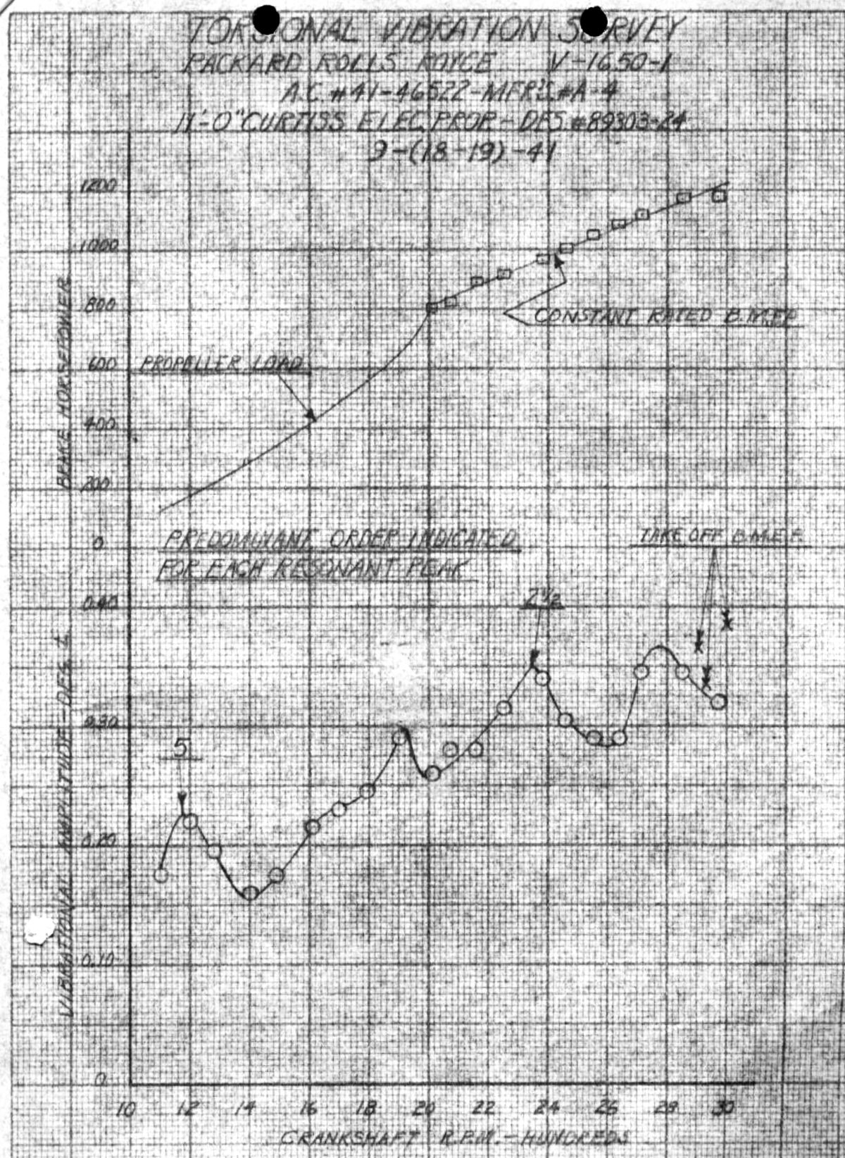
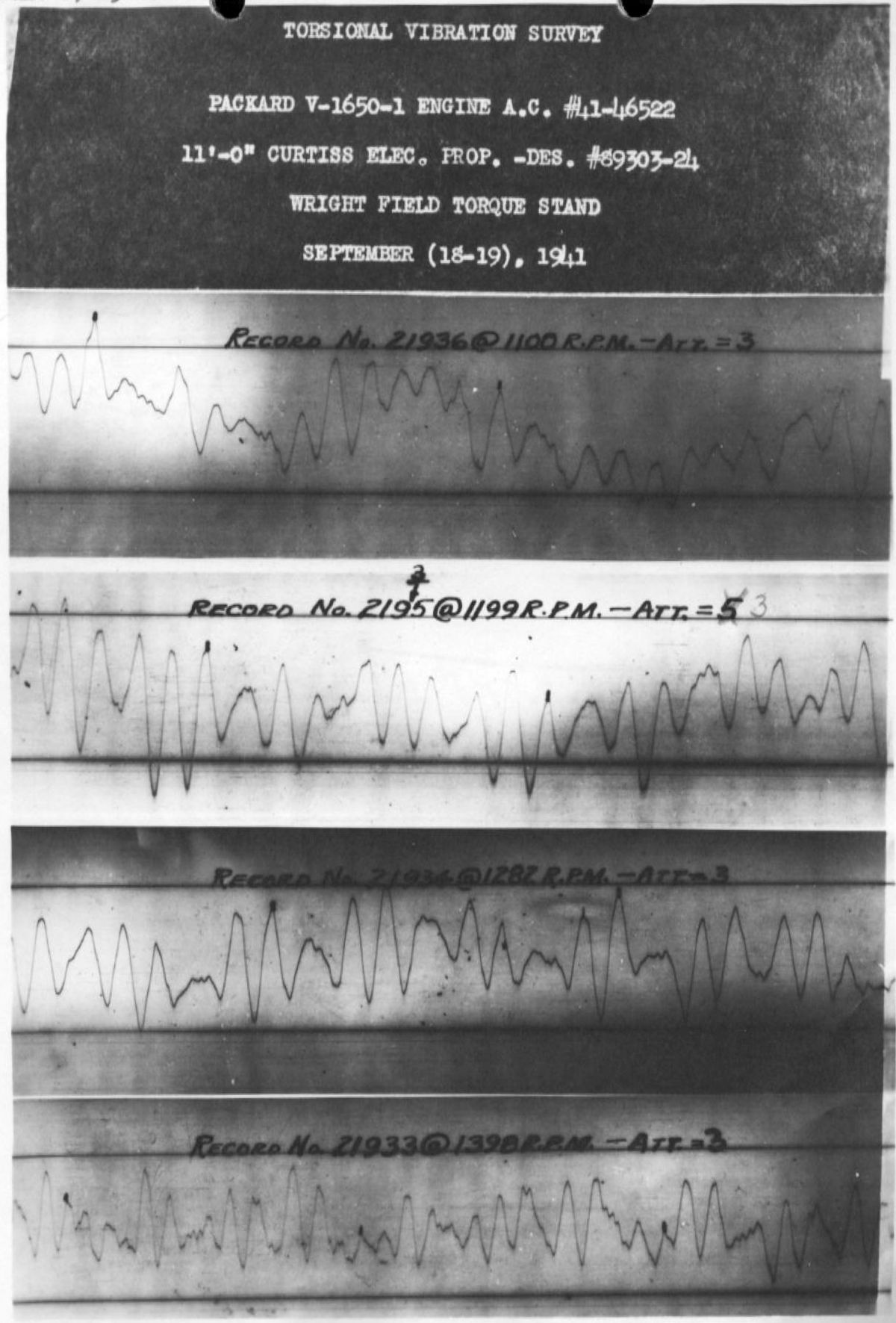
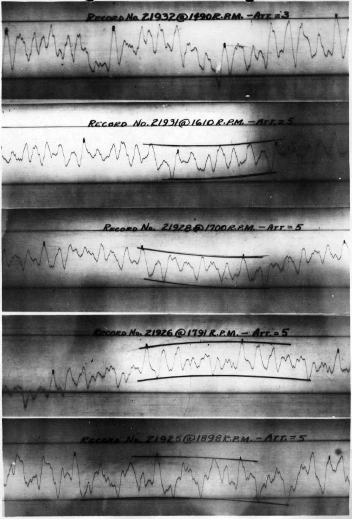
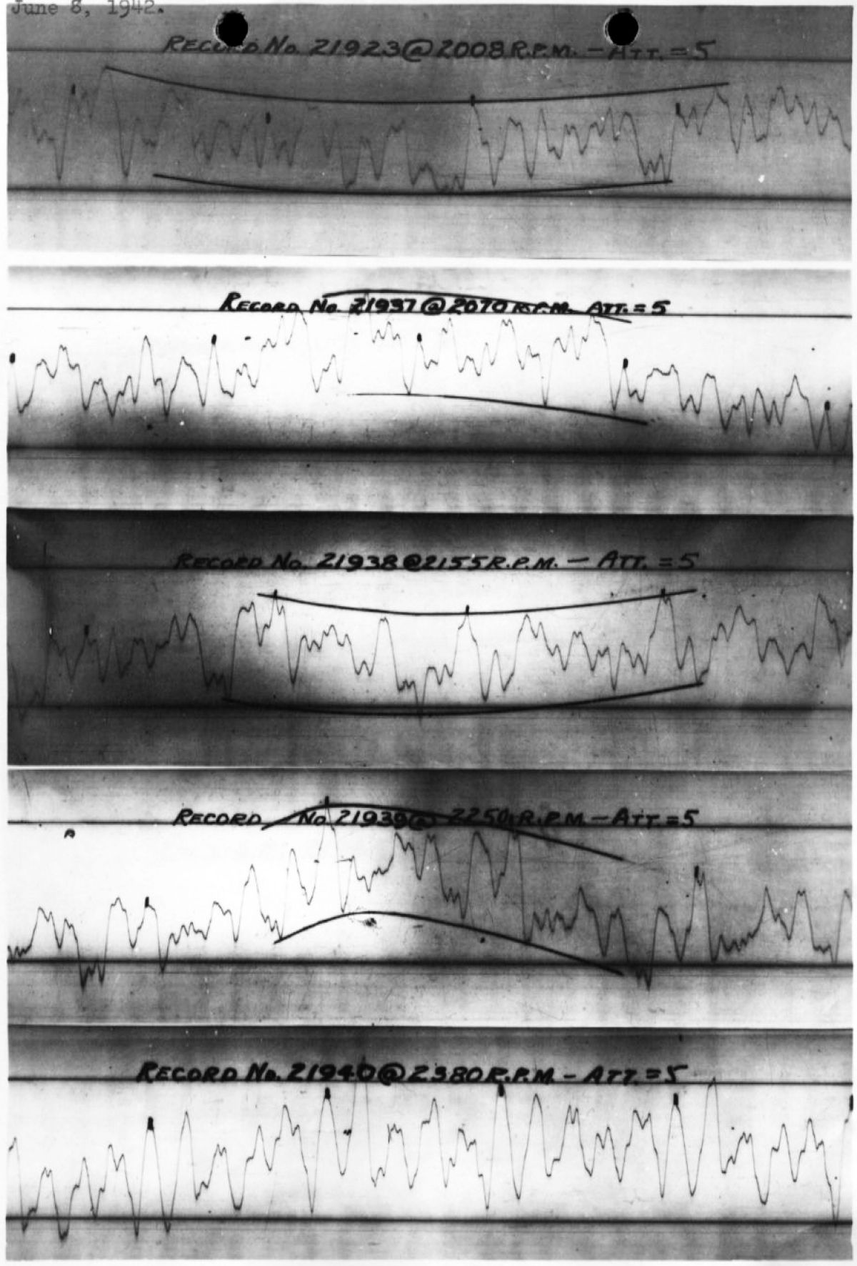
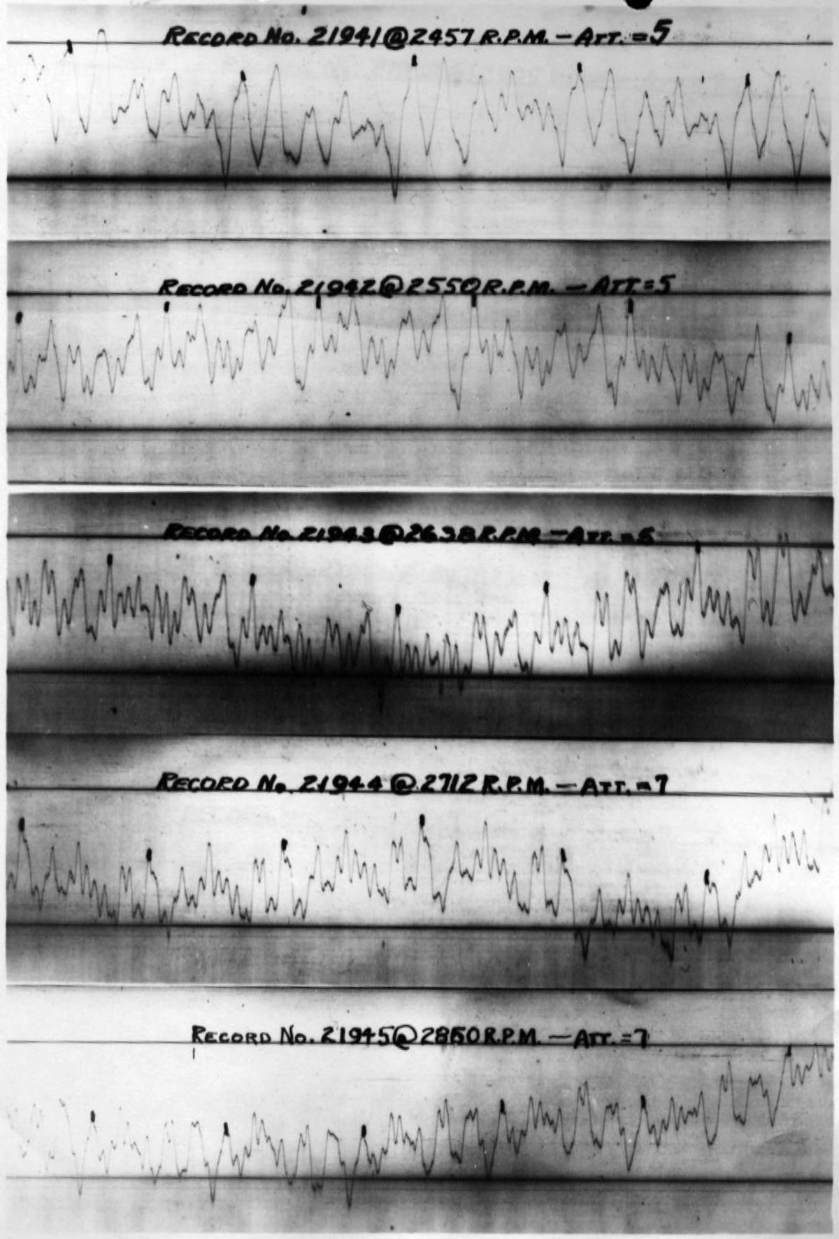
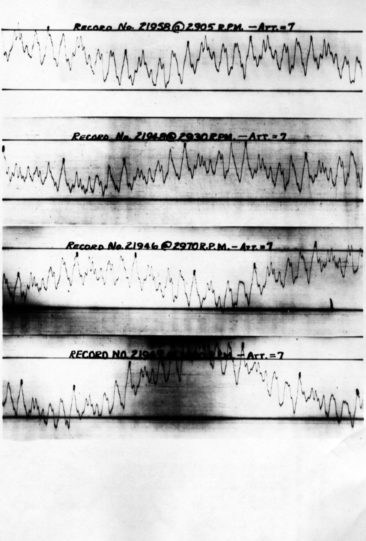
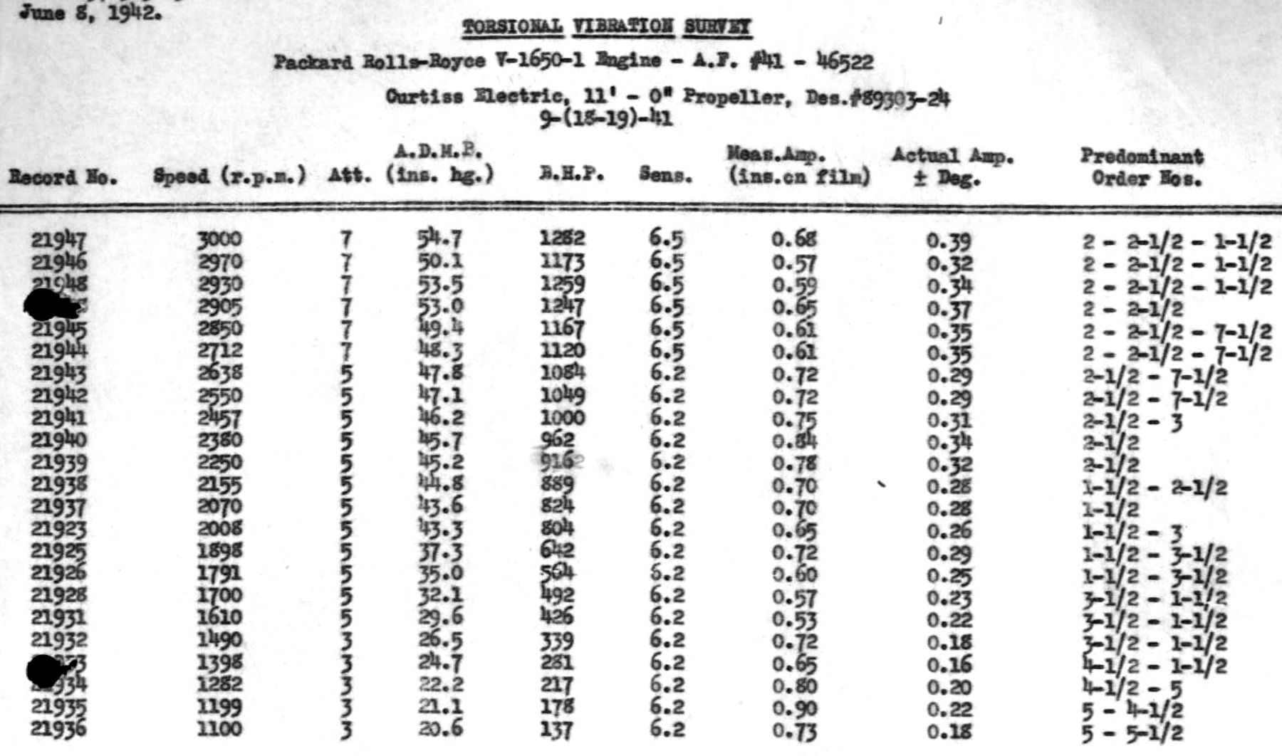
8 Jun 1942. R.L. King, a MatCmd Propeller Laboratory vibration specialist, performed a vibration survey on Packard V-1650-1, AAF No. 41-46522, with a Curtiss Electric 11' 0" diameter propeller, design No. 89303-24, in accordance with AN Specification No. 9504. The following engine ratings were used:
| Low Blower | High Blower |
|---|
| Normal Rated Power at 44.2 inHgA |
|---|
| 1,000 bhp | 2,650 rpm | Sea Level | 1,010 bhp | 2,650 rpm | 16,000 ft |
| 1,080 bhp | 2,650 rpm | 9,500 ft | | | |
| Maximum Power at 48.24 inHgA |
|---|
| 1,235 bhp | 3,000 rpm | 11,500 ft | 1,120 bhp | 3,000 rpm | 18,500 ft |
| Maximum Takeoff Power at 54.3 inHgA |
|---|
| 1,300 bhp | 3,000 rpm | Sea Level | | | |
This engine's propeller reduction gear ratio was 0.477:1. Sperry-MIT instrumentation was used. Hall concluded, based on the test, that the V-1650-1 torsional vibration was within the limits set by AN Specification No. 9504, and that the engine/propeller combination was satisfactory, but recommended a detailed crankshaft system vibration analysis so that more specific information would be available.
Results Explanation. Since the crankshaft rear was inaccessible a torsiograph drive was designed that used the quill shaft inner member that carried the propeller reduction pinion gear. The shaft section between the crankshaft front and adapter takeoff was of sufficient rigidity that vibration measurement was the same as the crankshaft front. The corresponding vibration amplitude at the crankshaft rear could be determined from knowledge of the normal engine elastic curve for the vibration node or nodes involved. No crankshaft system analysis had been made at this time and an accurate estimation of crankshaft rear deflection could be made. Previous analysis of similar engines suggested that frequency values and vibration modes expected could be approximated and the vibration modes probably occurring in the crankshaft could be determined. The approximation method served until actual crankshaft analysis was made.
An explanation of the vibration traces obtained during this test revealed the following (approximated) critical speeds and maximum recurring amplitudes:
| Speed (rpm) | Order No. | Frequency (Hz) | Maximum Recurring Amplitude (± deg) |
|---|
| 1,180 | 5 | 97.4 | 0.23 |
| 2,350 | 2 ½ | 98.0 | 0.35 |
The excitation frequency for the above orders was approximately 98 Hz and was probably occurring for the second vibration mode with one node located close to the propeller hub and another in the accessory drive shaft. The allowable amplitude for this vibration type in a six-throw crankshaft incorporating a quill drive in the propeller reduction system was ±1.5° measured at the crankshaft rear (AN Specification No 9504). Although the exact nature of the normal elastic crankshaft curves were unknown and the deflections at the crankshaft rear could not be determined until known values were obtained. Actual deflection was estimated to be well within limits since the maximum measured amplitude measured at the shaft front was 25% if that allowed at the crankshaft rear.
The maximum amplitude of ±0.39° occurred at takeoff bmep and 3,000 rpm. Above 2,500 rpm, a 7 ½ order excitation reached its peak at approximately 2,700 rpm. Assuming 2,700 rpm as the critical speed for this order, the natural frequency for this torsion vibration mode would have been 337 Hz. This was believed to be the third vibration mode with nodes probably located near the propeller hub, crankshaft center, and accessory drive shaft. The deflections at the shaft front and rear would have been nearly equivalent for this vibration mode. The allowable amplitude for this vibration type was ± 0.25° (AN Specification No. 9504). The estimated component amplitude measured at the crankshaft front for this excitation was within these limits and since the amplitude at the shaft rear would have been approximately the same, this amplitude was considered safe. A torsional vibration analysis for this crankshaft was to be made by MatCmd in the near future so that this report's conclusions could be verified. [8 Jun 1942 Memorandum Report EXP-M-57-503-638. Torsional Vibration Survey of the Packard Rolls-Royce V-1650-1 Engine. 147 – 158, P192386.]
9 Jun 1942. Responding to a propeller testing status request from the Moorgate (Canada) Agency Limited, New York, NY, the Experimental Engineering Section wrote that all 100-hr endurance tests on a V-1650-1 engine rated at 1,000 hp at 2,600 rpm and the 10-hr endurance run at a takeoff power of 1,075 hp at 3,000 rpm had been completed with no damage to the Hydulignum blades. Hydulignum was a high-strength, densified wood laminate made from compressed birch or beech veneers covered with cloth and bonded with synthetic resin and heat. The process had been developed in the late 1930s by the British Hordern-Richmond Aircraft Company. The propeller was being prepared for P-40F flight tests that were scheduled for late June. Experimental Engineering promised to notify the Moorgate Agency once tests were complete. [Cross Reference 452.025 – Propellers, Hordern-Richmond Hydulignum. 159.]
9 Jun 1942. Packard Service Manager Paul Dumas wrote MatCmd complaining that only a few operating squadrons were equipped with the proper coolant pump grease for the Packard-built Rolls-Royce engines. As far as Dumas knew, the only lubricant that would give satisfactory results was Secony Vacumn Intava P.D. 403H graphite grease, which had been given Air Corps Specification 3599 months ago. Dumas opined that the considerable leaking and some scoring of coolant pump shafts could be reduced or eliminated by using the approved lubricant. Dumas requested that the squadrons operating P-40F airplanes be equipped with the 3599 grease and volunteered to do so from the Packard supply if it could not be done through military channels. [Letter, Dumas to MatCmd. 160.] On 24 Jun 1942, Col O.R. Cook wrote Packard stating that Air Corps Specification 3599 grease had never been approved. Present maintenance policy was to use Air Specification VV-G-671A grease which had "functioned perfectly" and therefore could be substituted for the grease recommended by Packard. Col Cook recommended that Packard investigate VV-G-671A as an approved substitute for the Specification 3599 grease in order to simplify field maintenance. [Letter, Col Cook to Packard. 199.] Packard Service Manager Paul Dumas responded on 1 Jul 1942 saying that 15 Packard Field Service Representatives indicated that excessive coolant pump leakage and in some cases rapid coolant pump shaft wear occurred with the various greases being used by the AAF. Packard had on previous occasions tried to use specification VV-G-671A and one or two other graphite greases carried in Federal and Air Corps Specifications, but without success; only Specification 3599 grease had been found satisfactory. Dumas had checked with the Packard Research Department, which reported that the melting point of AN-VV-G-671A was so low that it ran out of bearings on test beds and during pump bench tests. [Letter, Dumas to Col Cook. 203 – 204.] On 14 Jul 1942, Col Carroll instructed the Maintenance Engineering Branch to stock and use Socony Vacuum No. PD-403-H grease for water pump shaft lubrication. A government specification for Socony grease was forthcoming in the near future. [IOM, Col Carroll to Maintenance Engineering. 240.] On 16 July, Col Carroll requested a report from Packard detailing all of the water pump grease testing Packard had done, and including the results of that testing. [Letter, Col Carroll to Dumas. 248.] Dumas replied to this request on 30 July, stating that the grease tested and found unsatisfactory was AN-VV-G-671, hard grade; no other type was tested. Pumps using this grease were operated on engines no Packard dynamometers, on engines in flight through the Packard service department, and on pump test stands at Chicago Pneumatic. All these tests showed the #3599 grease to be superior. [Letter, Dumas to Col Carroll. 282. On 7 Aug 1942, Contract Section Chief A.E. Jones wrote Packard stating that the Materials Laboratory had received a letter from the Washington, DC Materials Laboratory Commanding General, who refused to approve any specifications peculiar to only a limited number of engines. MatCmd realized the importance of securing a grease similar to Specification AC-3599 and requested that Packard contact the Socony Vacuum Oil Company and secure bids for supplying Intava P8-403-H grease, which was the same grease as the reference specification. It was necessary to place a 2-lb can in the tool kit of each V-1650-1 engine shipped. This can was to be constructed so that the grease could be easily transferred to the coolant pump grease cup, and was to be marked for ready identification and intended use. MatCmd wanted to be advised of Socony Vacuum's reply and the reference grease for each tool kit. [Letter, Col Jones to Packard. 292.]
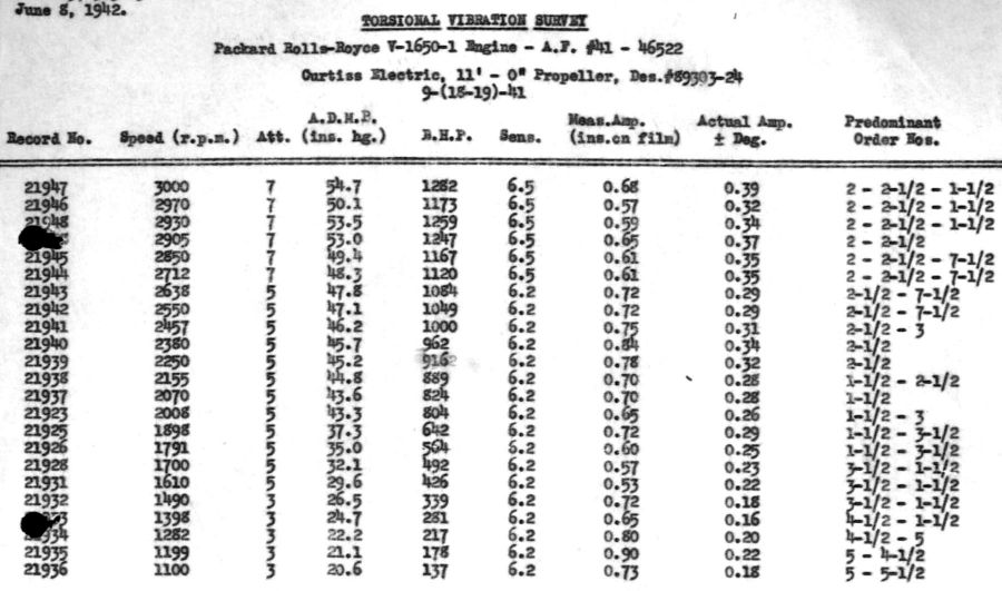 |
| Packard V-1650-1 Torsional Vibration Records |
11 Jun 1942. A conference in Detroit including Messrs. Vincent, Christopher, Perguson, Graves, Barker and Brown, representing Packard, Messers. Reed and Ellors representing the British Air Commission, and Maj Dexter, Messers. Hedwell and Ford Prescott representing MatCmd, was called to discuss the Packard Merlin engine. (Note: several citations, reported later, chronicled the events that led to this conference.) Ford Prescott authored the report.
Vincent discussed items related to the recent Packard Merlin testing program, especially in relation to production methods. Numerous modifications had been proposed and adopted as a result of conferences with the British representatives; these were disclosed on blueprints furnished to MatCmd covering the necessary changes.
The propeller shaft oil seal had not been satisfactory and a more effective seal with a larger diameter slinger and provisions for draining oil held back by the slinger had been devised. Packard Layout No. 585 covered this. MatCmd though the revisions would result in a more serviceable engine although the change was to be adopted after sufficient testing.
The rear camshaft bearing lock plate had not been satisfactory and Packard had evolved a different design that was fully interchangeable with the British design, but provided a more satisfactory gland locking method.
Packard had addressed loosening camshaft retaining studs by enlarging the stud lower ends.
The carburetor air scoop had been modified to accommodate exterior studs with elastic stop nuts. Previously, broken studs had been ingested into the supercharger, damaging the impeller and diffuser.
The R-R coolant pump had been perpetually leaky. The pump incorporated a seal similar to the Garlock brand, but of British make. Packard had used a Garlock 161 packing with satisfactory results. However, a completely new coolant pump design incorporating a more satisfactory bearing layout and a carbon seal that had worked in numerous automotive and aircraft engines. British representatives had approved the design and Packard planned to construct and test the modified pump.
Crankcase breathers had been throwing oil during tests. Packard modified the front breather and introduced a new rear breather, which reduced the crankcase pressure to almost zero and nearly eliminated crankcase oil loss.
Packard used a neoprene o-ring for coolant transfer openings between the block and head; the British part was natural rubber. The neoprene part was leaking occasionally and the natural rubber ring was thought to be better. In studying the problem, Packard was investigating a sealing ring with a U-shaped cross section in which the coolant pressure would press the ring tighter into the head and block.
Packard was attempting to evolve a more satisfactory sealing setup between the cylinder sleeves and cylinder heads. Considerable experimentation established that the old design worked well if steel washers replaced the aluminum washers on the cylinder barrel flange underside. The spacer blocks installed at either cylinder block end had been modified by relieving a portion of the spacer block adjacent to the cylinder flange. The narrower land, 0.188" wide, at the spacer block outer edge ensured sufficient contact between the cylinder sleeve flange and its gasket, preventing compression leakage at those points. Although Packard intended to adopt the latest British design as early as possible, this interim design would save cylinder blocks that were already manufactured. The new cylinder block design was interchangeable with the older designs, but the L-shaped spacer collar used at the cylinder sleeve bottom was troublesome due to insufficient machine capacity. Packard planned to test and adopt new high-tensile-strength alloy steel cylinder studs as quickly as they could be manufactured.
Magneto breaker springs were failing at a sharp bend was made over the breaker arm's rounded portion. A new spring design with two laminations had been tested and gave much better life than a single spring. The new two-leaf design stressed the spring material less and probably also provided some damping due to the two springs rubbing on one another. Additional tests were ongoing.
Several magneto distributor rotors had failed with the rubber breaking down and allowing the spark to pass through it at a thin section formed in the rotor counterbore bottom. The material thickness at that point had been increased and Buna rubber tests were very encouraging; the former 40% rejection rate had decreased to 4%. This test subjected the parts to 35 KV RMS.
Starter jaws had failed to engage on some engines. This was caused by an assembly error of two high-speed supercharger intermediate shafts. One had starter jaws cut on it while the other did not. If the shafts were switched there was no jaw to engage the starting motor.
Some spark plugs had been loosening after two or three flight hours. The spark plug inserts in use had a 0.0016" to 0.0116" clearance, which Packard considered excessive; it recommended the adoption of SAE standard fits of 0.001" to 0.008" loose. R-R had also suggested replacing the standard bronze spark plug inserts with stainless steel. These had been made and were awaiting test.
The leaking PN 605020 gasket where two high-pressure oil lines were joined had been addressed by increasing the width of the sealing surfaces and providing a different gasket material.
The starter motor was interfering with airframe parts in some installations. The brush cover had been modified to eliminate this interference. British representatives had requested this change to all British engines. The starter motor clutch sometimes slipped at a setting of 105 lb. A change had been introduced to increase the clutch setting to 245 lb. This direct-cranking starter was expected to operate satisfactorily with the increased torque setting.
A venturi type supercharger volute drain incorporated in the carburetor gave trouble when the engines were idled. Packard layout 623 modified this supercharger drain and improved engine idling.
It was possible to move the British two-speed supercharger mechanism control to a position where both high- and low-speed clutches were engaged simultaneously. Packard devised a new mechanism that prevented this by using an over-center scheme so that when the control was moved to a certain point the mechanism tripped over to the other position. In the air, this took place by automatic control over a 2,000 ft altitude range, preventing rapid surging back and forth from high to low and low to high at the automatic changeover point. Packard layout 564 depicted this mechanism.
Generator bracket studs had been stripping out of the generator adapters. Packard had introduced a new adapter design using through bolts and elastic stop nuts that made all bolts accessible for maintenance. Packard planned to submit a new-design generator bracket sample to MatCmd for approval.
Exhaust flange mounting studs and nut locks were troublesome. Packard layout 640 depicted a modification that R-R wanted introduced as quickly as possible. It consisted of a flame deflector installed between two exhaust gaskets.
The supercharger impeller shaft outboard bearing had two floating bushing with closed ends. When the shaft was installed the bushings were held in place but they fell out when the shaft was not installed. R-R recommended introducing a retaining circlip as shown on layout 615 but Packard did not want to introduce this as there was a danger of scratching or damaging the bearings when installing or removing the circlips. No change was contemplated.
 |
| Reach Nut |
Studs attaching the Cuno filter to the engine were troublesome. Packard had modified the filter to utilize reach nuts to attach the Cuno filter without disassembling other engine parts. This was shown in layout 612.
Packard planned to replace the cast iron intake valve guides with bronze ones after testing of the new guides was complete.
Main and connecting rod bearings shell backs were copper plated to prevent fretting. Packard's testing had not identified any advantage to the copper plating other than corrosion resistance. A theory existed that two materials that alloyed together would fret or gall under conditions of very slight motion under pressure, and that materials that did not alloy together should be used to prevent material pickup from the parts. MatCmd opined that silver might be a better material than copper for both corrosion and frettage prevention.
Several connecting rods had broken at a point adjacent to the connecting rod bolts, where the rod had shown the maximum frettage or galling, which may have started a fatigue crack. Two rods were found in which the fatigue crack had not progressed to failure, indicating that the cracks started at the point of maximum galling damage. Packard proposed nitriding the fork rod to obtain greater fatigue strength and resistance to galling between the fork rod and connecting rod bearing upper half. Connecting rod bolt installation where the bolts were slightly stretched had produced better results as this condition provided the maximum bolt tension possible since it was stretched to a point slightly exceeding the material's proportional limit. This was similar to experience with cylinder hold-down studs where studs tightened 50% more than previously had eliminated stud fatigue failure because increased tension prevented the parts from separating under load, eliminating fatigue action on the studs. This was demonstrated on R-R studs by pulling some rod assemblies in a test machine, where it was found that 0.0015" feeler gauges could be inserted between the connecting rod and upper rod bearing half at loads between 10,000 and 23,000 lbs, depending on how much the rod bolts had been tightened. The team proposed tightening rod bolts to a stretch of at least 0.006" in the future.
Vincent stated that a service item recommended by MatCmd was grinding crankshaft journals after nitriding. Mr. Reed of the British Air Commission advised against this procedure because a number of crankshaft failures had been attributed to grinding through the nitride case. The consensus was that crankshaft regrinding was unnecessary because the wear rate for nitrided shafts was low and their life long. Crankshafts that had been damaged by bearing failures should be replaced as the nitrided case was likely to have been damaged by such treatment.
Vincent stated that R-R had recommended chrome plating worn cylinder liners and honing them to size. MatCmd proposed to install lapping equipment to hone cylinders 0.030" oversize. However, no oversize pistons or rings existed. A more satisfactory repair was to replace the cylinder sleeve and installing standard pistons and rings. Reed stated that R-R had reclaimed cylinders by chrome plating to standard sized for some time and considered the method feasible and preferable to using oversize pistons and rings.
Packard planned to use the new cylinder block and sleeve design in conjunction with high-strength studs on all two-stage engines. The layout 530 design was proposed as an alternate until the entire British design could be incorporated. The two-stage engines were also to use heavier connecting rods similar to the Rolls-Royce model 61 rods. There was no discussion of crankcase and supercharger housing cracks, or of methods to overcome this difficulty. Numerous cracks had been discovered in those parts after tests had been run. The design and casting technique would have to be improved to eliminate such failures. [18 Jun 1942 Memorandum Report EXP-M-57-503-644. Rolls-Royce Packard Engine. P192343.]
13 Jun 1942. Col Carroll alerted the Air Service Command that in at least one case a carburetor and supercharger elbow had been changed as a unit. This was attributed to the fact that early V-1650-1 carburetor purchases had included both the carburetor body and supercharger elbow. He reminded the Air Service Command that T.O. 02-55AA-2, Section IX, Chapter1 stated that it was imperative that the original supercharger inlet elbows be retained as switching elbows could result in failure of the supercharger tail shaft bearing due to misalignment and poor bearing fit. He believed that some carburetor assemblies then in stock had inlet elbows attached and that service activities should be cautioned that the elbows originally supplied with the engines were to be retained. Later replacement carburetor purchases did not include this elbow. [IOM, Col Carroll to Air Service Command. 167.] On 3 Aug 1942, 1st Lt George Nassauer, Jr, an assistant in the Air Force Section, initiated a program whereby Bendix carburetor parts lists were revised to incorporate only the carburetor and furl discharge assembly incorporating the accelerator pump. Existing contracts had been changed to delete the carburetor elbow assembly from future spare carburetors delivered. Arrangements had also been made to have carburetor elbows stocked as engine parts, and instructions had been issued to Fairfield Ai Depot through the Supply Section to remove carburetor elbows from the spare carburetors in stock and forward them to the engine stock room. The revised Bendix parts lists were being incorporated in the applicable technical orders. [1st Indorsement, 1st Lt Nassauer to Col Carroll. 287.]
15 Jun 1942. 2nd Lt L.E. Kinkade reported on his visit to Mills Field, San Francisco, California and Paine Field, Everett, Washington where both organizations were reporting V-1650-1 problems similar to others previously mentioned. He also reported aircraft and engine installation problems not previously described.
V-1650-1 Engine Difficulties
1) Oil leaking past the propeller shaft oil seal and covering the windshield.
2) High-pressure oil seal at propeller shaft end leaking.
3) Propeller governor, vacuum pump and reduction gear high-pressure oil line gasket leaks.
4) Carburetor intake flange studs breaking.
P-40F Airplane and Controls Difficulties
1) Carburetor heat control rod breakage.
2) Intake air scoop cracking.
3) Intake air scoop butterfly shaft end bushings loose.
4) Cold air inlet butterfly loosening on its shaft; in one case where the butterfly was riveted to the shaft the shaft broke.
5) Header tanks leaking around the pop-off valve fitting.
6) Propeller relay switch high-pitch contacts going bad.
7) When the cockpit control quadrant lock was released the mixture and propeller control levers moved with the throttle. On takeoff the propeller control vibrated back to a low-rpm setting.
8) Six cases of cowl flap hinges breaking.
9) Electric shutter control not dependable, with several cases where the control failed outright.
10) Four cases of cowl flap indicator instrument failures.
11) Booster coil burning out while engine was being started.
12) Dirt collecting between windshields and distorting gun sight.
13) Engine could not be started by hand or by using the energizer.
14) No connections for using a battery cart.
15) Mixture control ball and socket joints wearing out.
16) Throttle rod breaking at joint.
17) Spare parts extremely hard to obtain.
Actions Taken
a) Engines that were leaking oil at the propeller shaft seals were reworked in accordance with Packard Layout Drawing 609, which incorporated a drilled passage in the reduction gear housing to relieve oil pressure on the propeller shaft seal.
b) Oil leaks at the propeller shaft end addressed by installing a gasket in the propeller shaft behind the plug and reinstalling the plug with white lead on the threads.
c) Packard was notified of the broken carburetor flange studs and was testing a proposed change at Patterson Field. This change incorporated four cap screws inside the air scoop and oversize studs with elastic stop nuts on the outside.
d) The propeller governor, vacuum pump and reduction gear high-pressure oil line gaskets were thought to be too thin. After the engine was run for some time the gaskets hardened and broke. New thicker gaskets were installed and Packard notified.
e) Airplane difficulties were reported to Lt Col Bradley, Pursuit Branch, Production Engineering and Service Liaison Unit, PPL.
In each case reported the necessary action was taken. [15 Jun 1942 Memorandum Report U-EXP-M-57-8230-1. Reported Difficulties on V-1650-1 Engine at Mills Field, San Francisco, Cal., and Paine Field, Everett, Wash. 169 – 171, P171306.]
15 Jun 1942. James. J Hiehaus of the Materials Laboratory reported on 52S-0 aluminum alloy tubing corrosion with V-1650-1 engines in P-40F aircraft. The first 47 aircraft delivered to Wayne County Airport, Romulus, Michigan had exhibited evidence of cooling system corrosion and all were grounded. Personnel from MatCmd's Production Engineering, Experimental Engineering, along with Harrison Radiator, Curtiss-Wright Service and Packard (hereinafter, "the team") were dispatched to investigate. Engines with 8 to 18 hrs time had greenish corrosion in the 52S-0 tubing interior; in the most severe cases, some flakes had washed free and settled as small sand-like particles in the drain lines and plugs. Anodized cylinder block interior surfaces that could be inspected appeared unaffected.
New Harrison radiators and those installed in the aircraft were sparsely coated on their exterior surfaces with greenish copper salts. A radiator that was sectioned at Harrison after it developed a leak in service had greenish copper salts in the radiator tubes. The team concluded that new radiator interior surfaces were probably corroded. Preliminary examination and analysis indicated that water-insoluble copper salts were formed in the radiator during manufacture and not removed by subsequent cleaning. It was also possible that some residua soldering flux, which was composed principally of zinc and ammonium chlorides, may have remained in the radiators after all washes were complete. Both copper salts and residual flux were partially or totally dissolved in the ethylene glycol-water coolant solution and circulated through the cooling system. This may have resulted in selective corrosion of non-anodized aluminum (like the 52S-0 tubing). Limited experimental data showed that chloride and sulfate contamination greatly accelerated the corrosive attack of ethylene glycol.
Coolant samples, a corroded aluminum tubing section, a radiator section, and samples of corrosion products were collected for examination by the Materials Laboratory. The corroded radiator samples were tested to develop a method of removing the corrosive copper salt. A 10% aqueous sodium potassium tartrate solution removed the salts without attacking the brass radiator components or lead-tin solder. Accordingly, instructions were issued to flush all radiators on the grounded airplanes with this solution for 10 min hot or 15 min cold. This action was apparently successful.
Corrosion product spectrographic analysis established that copper (from radiator salts) and aluminum (from corroded 52S-0 tubing) were the principal constituent. Phosphorus was also present in all samples; this was attributed to the presence of triethanolamine phosphate, an ethylene glycol corrosion inhibitor. Zinc, lead and tin presence indicated the radiator tubes or solder were also attacked by either the soldering flux or contaminated coolant. Other trace elements detected were probably corrosion products of other metals or dirt. All coolant samples tested showed that the ethylene glycol they contained was corrosion-inhibited.
Chemists speculated that if the coolant had been made up with chlorinated tap water the chloride contamination might have accelerated the aluminum corrosion. Harrison Radiator changed its cleaning procedure to eliminate copper salts. The bare 52S-0 tubing was replaced with anodized tubing. Service personnel were instructed to use distilled water when making up coolant. After an average of around 100 hrs each, all 47 aircraft were free of coolant contamination and component corrosion. [15 Jun 1942 Memorandum Report EXP-M-57-523-163. Corrosion of Aluminum Alloy Tubing on Cooling Systems of Rolls-Royce V-1650 Engines, Curtiss P-40F Airplanes. 172 – 178, P161282.]
15 Jun 1942. Packard was having trouble procuring machine tools for V-1650-3 supercharger production. MatCmd wanted the tooling by 1 Sep 1942 in order to meet V-1650-3 engine commitments starting 5 Oct 1942. [Cross Reference 452.9-17 – Supercharger Production. 179.]
Contract W-535-ac-23642 was in effect with Packard for engine maintenance parts that entirely finished for engine production and for spare parts. Contract W-535-ac-15768 covered parts that were completely or partially processed by Packard at its own plant. A 1st Indorsement stated that supplemental agreement on Packard contracts then being prepared would allow delivery of spare parts from either contract. Both Packard and Production Engineering realized the urgency and necessity spare parts delivery up to the schedule outlined in the contract. A 3rd Indorsement invited attention to Contract W-535-ac-15768's latest revision whereby spare parts could be drawn to meet requirements even at the expense of production. [Cross Reference 452.8 – 1650-1 Packard. 180.]
15 Jun 1942. Production Engineering Chief Col O.R. Cook wrote Paul Dumas at Packard regarding Packard Service Memorandum No. 5, noting the following statement:
"This control should never be used except with the supercharger in low speed and the pressure will therefore begin to fall off (from 54.3 inHgA when properly calibrated) at approximately 8,600 ft. Broadly speaking, therefore,, this device is useful only in an emergency below 10,000 ft."
If this is true modification should be made so that the emergency valve can be used in high supercharger gear ratio, as pilots in combat are much more likely to need extra power at altitudes above 10,000 ft than below. A study of the emergency valve construction revealed no reason why it could not be used for high blower operation, and from the standpoint of engine operation, no reason can be seen for not allowing pressures of 54.3 inHgA in high blower. Possibly there was some reason for which this was not apparent. Comments were requested. [Letter, Col O.R. Cook to Paul Dumas. 181]
17 Jun 1942. Experimental Engineering noted that the 14 mm spark plugs used in the V-1650 required 13/16" socket wrenches, few of which were available throughout the AAF. A suitable socket wrench drawing, AAF No. 42A15967, had been prepared. The writer recommended that a sufficient quantity of these sockets to cover V-1650 engine requirements be procured since an actual shortage apparently existed. [Cross Reference 452.8 – V-1650 Engine. 184.]
18 Jun 1942. E.H. Smith, an AAF Resident Representative at Packard, cabled Production Engineering asking that Packard be given authority to release V-1650-3 engine information to North American Aviation. [Teletype, AAFRR to Experimental Engineering. 188.] Col. A.E. Jones cabled the permission release on 19 Jun 1942. [Teletype PES-TWX-504. 192.]
19 Jun 1942. The British requested a rush order of engine parts from Packard for Merlin engine production in England.
2,000 Coolant Pumps
500 Connecting Rod Sets
500 Camshaft Pairs
1,000 Finished Camshafts
500 Rocker Sets
1,000 Sets Housing D 10330
1,000 Sets Trunnion D 10331
1,000 Bushing Sets (each set consisting of 28 unique part numbers and 101 total pieces)
[Teletype AIRWBP-6-415. 190 – 191.]
24 Jun 1942. Col Alden R. Crawford, AAF Technical Executive wrote the Executive in the Commanding General's Office, AAF Materiel Command, Washington, D.C. regarding delivery of Packard V-1650-1 maintenance parts. The Production and Planning Officer at AAF Central Procurement District in Detroit and the AAF representative at Packard had investigated this matter, and it was discussed in detail at a conference held at Packard on 18 Jun 1942. The following information was developed:
a. Spare parts were not ordered at the time the engine contract was placed but were called fo on contracts supplementary to the engine contract.
b. Approximately 55% of spare parts were manufactured complete outside the Packard plant.
c. There were two spare parts contracts; one was a cost-plus-fixed-fee for parts manufactured by Packard, the other was a fixed price contract for the 55% manufactured complete in vendors' plants. The former contract called for delivery to the Government from the Packard Plant and the latter called for delivery to the Government direct from vendors' plants. Included in the latter contract were such items as oversize studs and bushings, which were not used in new engine production.
d. Based on total parts orders, spare parts shipments were ahead of engine shipments. However, some items such as oversize studs, bushings, etc. that were procured directly from vendors, had not been shipped at all. Packard was taking action to correct this situation and in cases where parts were required immediately, some had been shipped from Packard production stock.
Packard was making every effort to improve spare parts delivery, especially those items that were in arrears. Shipping instructions were to be amended so that spares could be shipped from either vendors' plants or from Packard, an arrangement that was expected to improve the situation. Packard realized the need to ship spares and the Packard AAF representative was holding down complete engine production so that the necessary spare parts could be shipped. Packard expected partial shipment of spares within the next 30 days and all spares to be shipped within 60 days. [Letter, Col Crawford to Executive. 196 – 197.]