|
|
 |
 |
|
|
|
|
|
|
 |
Accessories and systems complete the engine. Carburetors, fuel injection systems, magnetos, generators, hydraulic pumps, starters, and vacuum pumps are all accessories; systems typically include fuel and cooling. While these are usually supplied by specialty or airframe manufacturers, they are nonetheless essential to the operation and performance of the engine. And like engines, they have development and operation tales of their own. |
Carburetors and Fuel Injection Systems
Aircraft Carburetors and Fuel Systems: A Brief History
Stromberg NA-S4 Carburetor Development
Carburetor Models and Usage --- Expanded to Include Float and Non-US Models (224K MS Excel Worksheet)
Contributed by Pete Law and expanded by Robert Mawhinney to include float and non-US carburetors.
Users are cautioned that this document may contain errors or omissions.
Evaporative Cooling
Part 1: Through WWII
Part 2: Post WWII
Other Power Plant Accessories
T.O. 00-25-29 - Maintenance Interchangeability Cross Reference Charts, WWII Aircraft
December 1943 (20MB PDF)
Includes Engines, Carburetors, Magnetos, and Many Other Accessories (Moved to Member’s Section)
The Air Annual of the Brithsh Empire - 1938: Magnetos, Starters, Carburettors, Sparking Plugs
Starters (1941)
The development of power plant accessory equipment goes back to a period immediately following the first World War, when flying was a haphazard and dangerous occupation. The only flight instruments were a compass, bubble, altimeter and tachometer. With these instruments, flights were occasionally made through clouds but not for protracted periods. Very few pilots were capable of flying blind even for the shortest period. After the World War and at the beginning of commercial aviation and the inauguration of airmail service in this country most of the flying was of the contact type. The development of the turn and bank indicator gave the first real help in blind flying. Then came the artificial horizon and gyro compass. The development of the radio range beam and directional radio made it possible and practical to fly without contact with the ground. With these instruments available, the art of blind flying developed rapidly and increased to the point where experimental flights entirely with instruments from "take-off" to landing have been successfully conducted.
Similarly, the development of the single engine airplane of the World War period, with its engine of 30 horsepower, to the huge multi-motored transport of today, wherein the output of a single cylinder is often equal to or more than the total output of the early engine, has brought about the development of power plant accessory equipment to its present stage. The days of engine starting, wherein the propeller was pulled through by hand, have long since disappeared to be replaced by electrically operated Inertia or Direct Cranking Electric Starters capable of transmitting 1500 pound feet of torque for the cranking of engines rated up to 2000 horsepower.
In a like manner, the development of generating equipment from the early wind driven types having an output of approximately 50 watts, to the engine driven types of 3000 watts capacity, has also taken place. In addition, the Venturi tube, which was subject to clogging with dirt and ice, has long since been replaced with engine driven vacuum pumps with capacities sufficient to provide proper suction for the operation of navigating instruments and pressure for the operation of wing and tail surface deicers. Whether the need has been for aircraft engine starting or for the generation of electric power, accessory units have proved vital necessities to the operation of the present day air transport and military airplane. Electric motors for the operation of retractable landing gear, wing flaps, tail wheels, etc.; hydraulic pumps, valves and control units for actuating hydraulically, full feathering propellers, retracting mechanisms, etc.; radio dynamotors for the operation of radio receivers and transmitters; fuel flow meters for determining fuel consumption; these are only a few of the many accessory units which have played an important part in the development and dependability of the present-day airplane. To the old time pilot the airplane may have consisted primarily of the airplane and its engine, but to the experienced air transport pilot of today aircraft accessory equipment and flight instruments play a major part in establishing flight security.
The fundamental requirements of any form of aircraft power plant accessory are dependability, minimum weight, simplicity of installation, ease of operation, effectiveness, serviceability, and low initial cost. As the number and type of power plant accessories are, necessarily, limited to the number of drives available on the rear or accessory drive section of the power plant, careful consideration must be given to the number of operations to be performed, and the type of
service to which the airplane is to be subjected, prior to the selection of accessory equipment. In addition, the capacity and type of accessory units to be installed on a given power plant are definitely limited to the physical characteristics, operating speed and torque limitations of the accessory drives available.
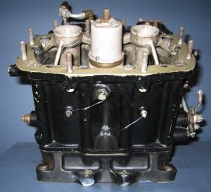
 Power plants of American manufacture, rated from approximately 400 to 2000 horsepower, are normally provided with starter, generator, and vacuum pump drives in addition to the standard dual magneto, tachometer, and fuel pump drives. Two auxiliary drives are also provided for use as gun synchronizer drives on military airplanes and may be used as additional accessory drives for commercial applications if required. Power plants rated at less than 400 horsepower are normally provided with starter and generator drives with a vacuum pump drive available as optional equipment. In addition, power plants rated at or in excess of 1000 horsepower may be provided with an extra accessory drive unit, which is normally installed on the generator drive and provides two additional drives for the operation of accessory equipment, such as engine driven hydraulic pumps for the operation of retracting mechanisms, automatic pilots, etc., or engine-driven alternators for Autosyn or radio power supply systems. The accessory drive or rear sections for the Pratt & Whitney Twin Wasp and Double Wasp engines are shown in Figures 1 and 2 respectively. As the operation and control of power plant accessory equipment such as starters, generators, vacuum and hydraulic pumps, is dependent on associated accessory equipment, a discussion of the complete system will be included under each individual basic power plant accessory.
Early Starting Equipment
 We do not have to go back many years to recall the days when we started our cars by turning a crank-handle and our motorcycles by pushing them. Later a "kick starter" was introduced for the motorcycle and a "self-starter," as it was called, for the automobile. The self-starter consisted of an electric motor operated from a battery and geared, when required, to the crankshaft. Similarly, the development of aircraft engine starting from the days of swinging the propeller by hand to the present-day type of direct cranking electric, inertia, and cartridge starters capable of cranking engines rated up to 2,000 horsepower, has been brought about by the constant increase in power plant size and the demand for quick and dependable engine starting without need of external assistance. Although the method of hand swinging the propeller for engine starting was satisfactory on early type aircraft engines of low horsepower, where the compression ratio was not excessive and low engine cranking speeds encountered, swinging the propeller by hand today on a cold morning would be a formidable undertaking, and in most cases entirely impossible, due to the use of geared propellers and the high horsepower output and compression ratio of present day large power plants.
Swinging the Prop
Although swinging the prop was the earliest common form of starting for aircraft engines and the method still in limited use for present-day light engines, there has always been considerable danger to the operator when effecting engine starting by this method. Swinging the prop, in most cases, has been replaced by the use of either a hand turning gear, air-injection starter, or direct cranking electric starter, the latter two methods providing quick and convenient starting by the pilot without need for external assistance. The need for mechanical aid in starting, evolved many methods which were short lived. Several, however, were successful to a certain degree.
The Hucks Starter
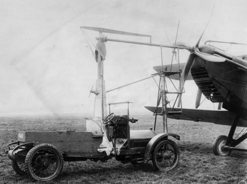
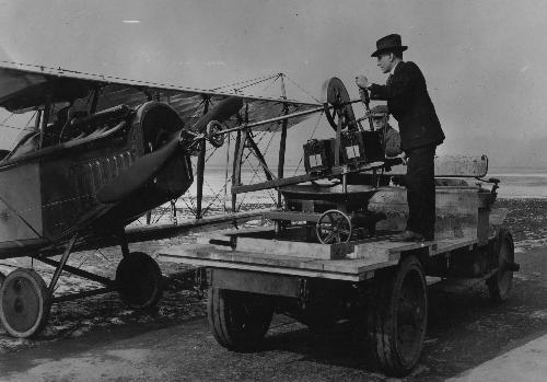 An early advance in the development of aircraft engine starting was the invention of the Hucks starter, which was named after its inventor. This unit was an external mechanical starter, employing a Ford motorcar chassis. A special chain from the gearbox was made to drive a layshaft mounted high up and adjustable. At the forward end of this shaft was a coupling which could be made to engage with a special "dogged" fitting attached to the propeller hub in the same manner as a motor-car crank handle was used to engage the engine crank shaft. Starting was effected by engaging the coupling and rotating the layshaft. Disengagement of the driving dog from the engine was automatic upon starting of the engine. The Hucks starter, although an improvement over the method of hand swinging was in turn, very impractical. Delays in starting occurred when there were a large number of airplanes to be started. Also, it was sometimes out of action or did not exist at places where a start was required. At the same time, it must be remembered that engines were increasing in size and compression ratio to the point where swinging of the propeller by hand as well as turning the propeller mechanically by means of the Hucks starter were impracticable. This brought about the development of the hand turning gear, which is used in a modified form at the present time for certain aircraft installations.
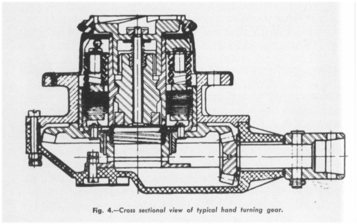
Hand Turning Gears
 The development of the band turning gear type of aircraft engine starter was primarily due to the need for an aircraft engine starter capable of cranking engines rated up to 600 horsepower not equipped with batteries or generators. The hand turning gear consists, in general, of a gear reduction unit, which operates an automatic engaging and disengaging mechanism through an adjustable torque overload release. Mechanical features are incorporated in the unit to safeguard both the operator and starter from injury in case of engine backfire. In case of the engine backfiring, the torque overload release automatically disconnects the starter drive, thus preventing damage to the starter mechanism. As a further protection to the operator, a ratchet is provided in the hand crankshaft to preclude the possible transmission of any reverse motion to the crank-handle. Unusual care is exercised in the design and manufacture of a hand turning gear to eliminate friction, thereby assuring maximum even cranking. In addition, the ratios of the gear reductions used have been carefully determined in order to permit the highest engine cranking speed consistent with the average manual effort which can be expended in cranking. Thus, the operator is assured of a prompt start with minimum effort, provided the other factors which influence engine starting are normal.
Air Injection Starter
 In limited use at the present time, the air injection starter has been developed as a light-weight and efficient starting means for aircraft engines rated up to 250 horsepower. Operated from self generated air pressure, this type of starter was particularly suitable for application on engines of small output where an electrical installation was not possible and manual hand-cranking undesirable and inadequate.
The Air injection starter equipment consisted of a small and compact engine-driven air compressor, a timed rotating distributing valve, integral with the compressor, a tubular air storage tank, an automatic pressure. regulating valve, pressure release starting valve, and an instrument panel mounted pressure gauge and primer. However, as the majority of light powered airplanes at the present time are equipped with engines designed to accommodate a generator of low output, the direct cranking electric type of starter is replacing the majority of air injection starter installations due to its light weight, simplified installation, and freedom from service troubles. Due to the extensive plumbing required, and the corresponding possibility of air leakage in the system, the air injection type of starter is only recommended for installations where battery and generator are not available. Although primarily confined to use on engines rated up to 250 horsepower, a starter employing this principle of operation is widely used on foreign aircraft for starting aircraft engines of all capacities.
 The principle of operation of the air injection starter is as follows: The engine is cranked from an initial air pressure of approximately 450 pounds per square inch, which is contained in a storage tank. Release of the compressed air is controlled from the pilot's compartment and is transmitted by a distributor valve to the cylinders in the proper cyclic order, thus rotating the engine. A portion of the compressed air, in passing through the distributing valve, forces liquid fuel into the cylinders on the compression stroke. This carburetor priming charge is followed by a greater volume of air which rotates the engine and assures instant firing. The air pressure dissipated in starting is replenished by the compressor shortly after the engine has been started. As the maximum operating pressure of 450 pounds per square inch is reached, the pressure regulating valve, which is an integral part of the storage tank, automatically stops further charging of the storage tank, thus the compressor, driven direct from the main aircraft engine, is temporarily relieved of pumping against pressure and rotates freely under no load until further dissipation of the air pressure by- starting occurs. Due to the variations which are encountered in different installation, no definite performance data can be given, however, under normal conditions, approximately 20 to 30 starts can be obtained from one fully charged tank of air without replenishment in the meantime.
Later Developments
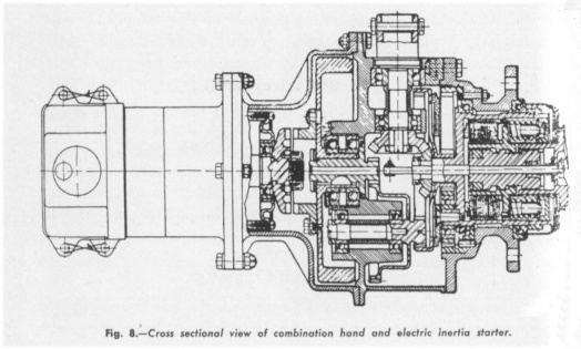
 Of more recent application in this country is the hand or combination hand and electric inertia starters, which have been designed primarily for use by the military services and are suitable for installation on engines rated up to 2,000 horsepower. The starters are particularly suited for installations where dependability and provisions for emergency hand-cranking are required. The basic design of all inertia starters consists of the storage of energy in a small flywheel by accelerating it to a high speed either manually or electrically. The energy thus stored is expended in rotating the engine crankshaft. Transmittal of the kinetic energy of the rotating flywheel to the engine is accomplished through reduction gearing, a multiple disc clutch, an engaging mechanism, and driving jaw.
The Inertia Starter
 The Inertia Starter incorporates the following advantages: Minimum weight in proportion to the cranking torque capacity of the starter. High initial cranking speed thereby assuring delivery of fuel to the cylinders and permitting starting with a greater degree of spark advance. Flywheel acceleration independent of engine size, frictional torque and weather conditions, thereby assuring minimum current draw when electrically operated. Torque overload release, consisting of a multiple disc clutch under adjustable spring pressure, thereby preventing damage to the engine or starter in case of overload or engine back fire. Automatic disengagement of motor jaw with flywheel jaw when starter is hand operated, thereby permitting band cranking with motor shaft disengaged. Starter operation, independent of electrical system, by means of hand crank with no decrease in starter performance. Acceleration of flywheel by some external means, such as an external energizer, thereby providing a reduction in weight by elimination of the motor and at the same time providing starting by use of the hand crank in event of emergency. Provisions for complete remote control of starter from pilot's compartment when electrically operated by use of a solenoid meshing device and solenoid starting switch. Starters manufactured by Eclipse Aviation are available for operation from 12 or 24 volt battery systems.
Electrical Starters
The increased use in aircraft of batteries and generators for battery charging has made available current sources of sufficient capacity to provide adequately for the electrical requirements of the direct cranking electric type of aircraft engine starters. The Direct Cranking Electric Starter presents many advantages which recommend its use in installations, where convenient engine starting is desired. The starter, controlled from the cockpit, provides instantaneous and continuous 'cranking. This feature is desirable in private and commercial air transport installations, where sufficient battery capacity is available, as it permits prompt starting without external assistance. Direct cranking electric starters are available in capacities for engines rated from 50 to 1500 horsepower.
This type of starter consists basically of an electric motor, a gear reduction and an automatic engaging and disengaging mechanism, which operates through an adjustable torque overload release. The engine is cranked directly by the starter and there is no preliminary storage of energy as with the inertia type of starter. Therefore, it can be assumed that for a specific engine under extreme low temperature conditions, with resultant high cranking torque, the current consumption will be somewhat higher than would be the case with an electric inertia starter on the same engine under similar conditions, because of the direct connection between the starter motor and the engine during the cranking period. The direct cranking electric starter is intended for use on large commercial transports and privately owned airplanes, which are normally stored in hangars and are not subject to cold weather starting. The use of external batteries in the form of a dolly are recommended for cranking engines of large aircraft transports equipped with direct cranking electric starters in order to save the airplane batteries.
Direct Cranking Starters

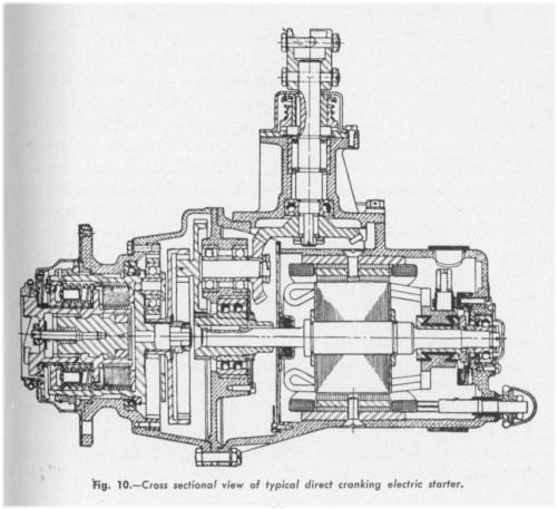 The direct cranking electric starters are normally furnished less hand crank mechanism with the exception of large capacity units which are supplied with a hand crank mechanism if required. The starters are designed for operation from a 12 or 24 volt battery source. Upon the application of current to the motor terminals, the torque of the motor is transmitted through a gear reduction unit to the adjustable torque overload release, which in turn actuates a splined screw shaft which moves the starter jaw axially outward into engagement with the engine cranking member before the starter jaw begins to rotate. Thus, complete engagement is effected before cranking commences. The torque overload release in the form of a multiple disc clutch is adjusted to a predetermined value so as to deliver sufficient, yet not excessive cranking torque to the engine. In case of engine back-fire, the clutch slips, preventing damage to the engine and starter. With this type of starter, engine cranking is continuous but at a lower speed than that obtained with the inertia type of starter. The current draw of the direct cranking electric starter varies directly with engine size and torque characteristics. It will therefore be considerably higher than that required for the operation of the inertia type starters.
The Combination Direct Cranking Electric Starter With Integral Hydraulic Feathering Pump
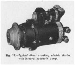 The direct cranking electric starter with integrally mounted hydraulic feathering pump has been developed to replace the standard type of direct cranking electric starter and separately mounted electric motor driven hydraulic feathering pump for installations utilizing the Hamilton Standard Hydromatic Propeller. Primarily designed and developed for use in conjunction with Hamilton Standard Hydromatic Propellers, the starter pump unit incorporates all of the features of the conventional direct cranking electric starter, with the exception that the hand crank mechanism fitted to starters of this type has been removed and a hydraulic pump mounted in its place. With this type of starter, a reversible motor is utilized in order to permit driving of the hydraulic feathering pump when the starter is not in operation. The starter pump unit, in addition to providing a saving in weight due to the elimination of an additional electric motor and excess line tubing, provides a compact and light weight installation integral with the power plant and available for operation as required. The design of the starter pump unit is such that when used in conjunction with two solenoid starting relays, battery booster coil and a suitable control switch, remote control of both starter and feathering pump is provided. As with the conventional type of direct cranking electric starter, jaw engagement is automatic upon closing of the motor circuit. An overrunning clutch, interposed between the starter and pump provides starter operation without rotation of the hydraulic pump. The hydraulic pump, which may be of either the internal or external gear type, provides a dependable and efficient source of hydraulic pressure for the feathering and unfeathering of Hamilton Standard Hydromatic Propellers.
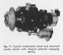
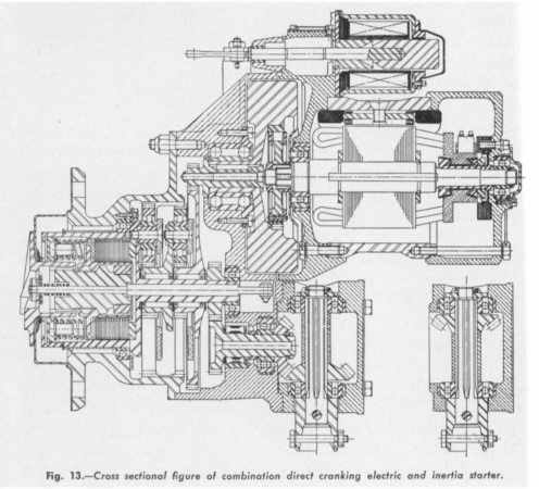
Combination Direct Cranking Electric And Inertia Starter With Integral Solenoid Engaging Device
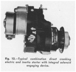 Among the most outstanding recent developments in aircraft engine starting equipment has been the combination direct cranking electric and inertia starter, which incorporates all the features of the hand or combination hand and electric inertia starters and in addition, provides, by means of a heavy duty integral accelerating motor, continuous cranking of the aircraft engine after dissipation of the flywheel kinetic energy. Thus the energy stored in the starter flywheel at the initial engagement of the starter and engine jaws is used to overcome the heavier breakaway torque after which the lighter load of continuous cranking is assumed by the electrical system. The result is notably less drain on the source of electrical energy with greater convenience and starting ease. Although only available at the present time for use in conjunction with engines, rated at approximately from 1500 to 1800 horsepower, this starter can be readily modified.
The design of the starter is such, that when used in conjunction with a separately mounted solenoid starting relay, battery booster coil and three position starter control switch, remote control of motor acceleration and starter jaw engagement is provided. The starter may be operated as a direct cranking electric starter or as a combination, direct cranking electric and inertia starter, by means of the control switch, as required. For cold weather starting, operation of the unit as a combination direct cranking electric and inertia starter is recommended, whereas for warm weather starting or where immediate continuous cranking is desired, the unit may be operated as a direct cranking electric starter. For emergency operation when the source of electrical energy is not sufficient to permit proper electrical operation as a combination direct cranking electric and inertia starter, the unit may be operated as an electric inertia starter, in which case manual engagement of starter and engine jaws is required. In addition, the unit may be operated as a hand inertia starter for emergency operation, in which case it is also necessary to manually engage the starter and engine jaws. A universal hand crank mechanism is provided on these starters with provisions for either clock or counter clock rotation hand cranking. With this type of hand crank mechanism the position for hand crank take off may be readily adjusted to facilitate starter installation, available for 12 or 24 volt operation.
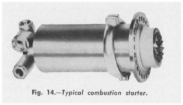
The Combustion Starter
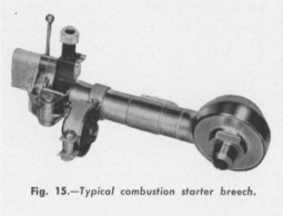
 The combustion starter has been developed as an efficient and compact means for providing instantaneous starting particularly on single engine military aircraft wherein minimum battery requirements are the prime consideration and emergency hand cranking not considered essential. The combustion starter equipment consists of a basic engine mounted starter, loading breech, and firing control switch. In operation, cranking torque is applied to the engine crank shaft by means of a piston and screw shaft arrangement, which is actuated by the release of concentrated energy stored in cartridge form and fired by means of an electrical contact from the main aircraft electrical system or a small dry cell battery. The loading breech is directly connected to the starter by tubing and is designed for mounting in either the engine nacelle or pilot's compartment where it is readily accessible for cartridge loading. A push button switch connected in the battery circuit and located in the pilot's compartment is utilized for closing the circuit to the firing mechanism in the loading breech. Automatic safety devices are incorporated in the starter and breech to prevent possible injury to engine, starter or operator in the event that engine torque requirements might exceed the rated capacity of the starter when utilized for cold weather starting. Efficient operation of the combustion starter is limited to installations wherein the maximum length of intake tubing between loading breech and starter is 28" to 32". In view of the above, the combustion type of starter is not recommended for installation in multi-engined airplanes, as control of the system cannot be maintained from the pilot's compartment. Combustion starters are available in three capacities at the present time for installation on engines rated up to 550 horsepower, 1250 horsepower and 2000 horsepower, respectively.
 |
 |
 |
Send mail to
![]() with questions or comments about this web site.
with questions or comments about this web site.
![]()