Righter 4‑O‑34
Restoring the 1944 Righter 4‑O‑34 Engine to Running Condition
Part 1: The Engine
by Tom Fey
Published 10 Mar 2022
| Part 1: The Engine | Part 2: Engine Mount and Running Stand | Part 3: Running the Engine |
Righter 4‑O‑34 |
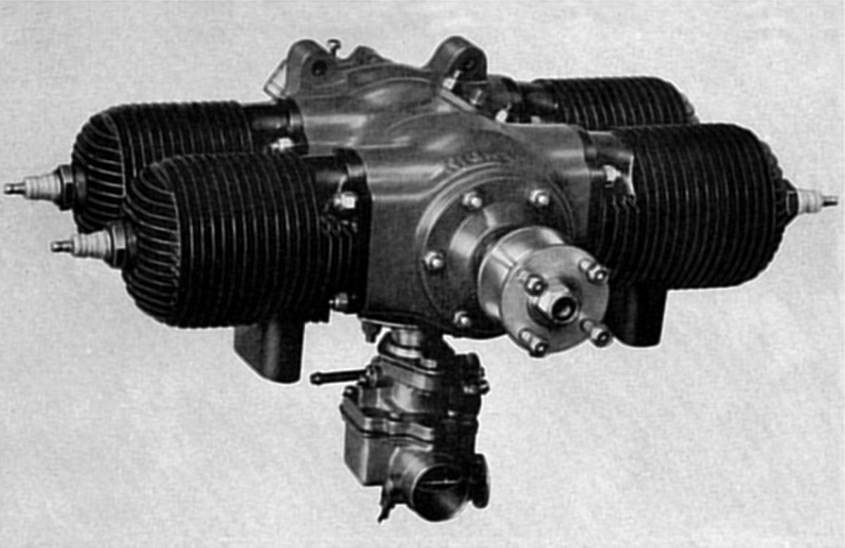
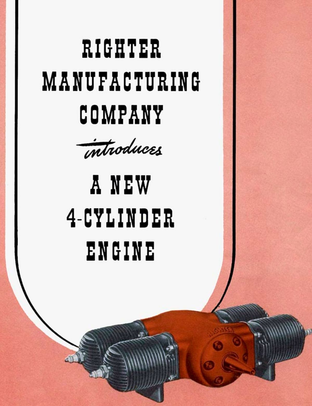
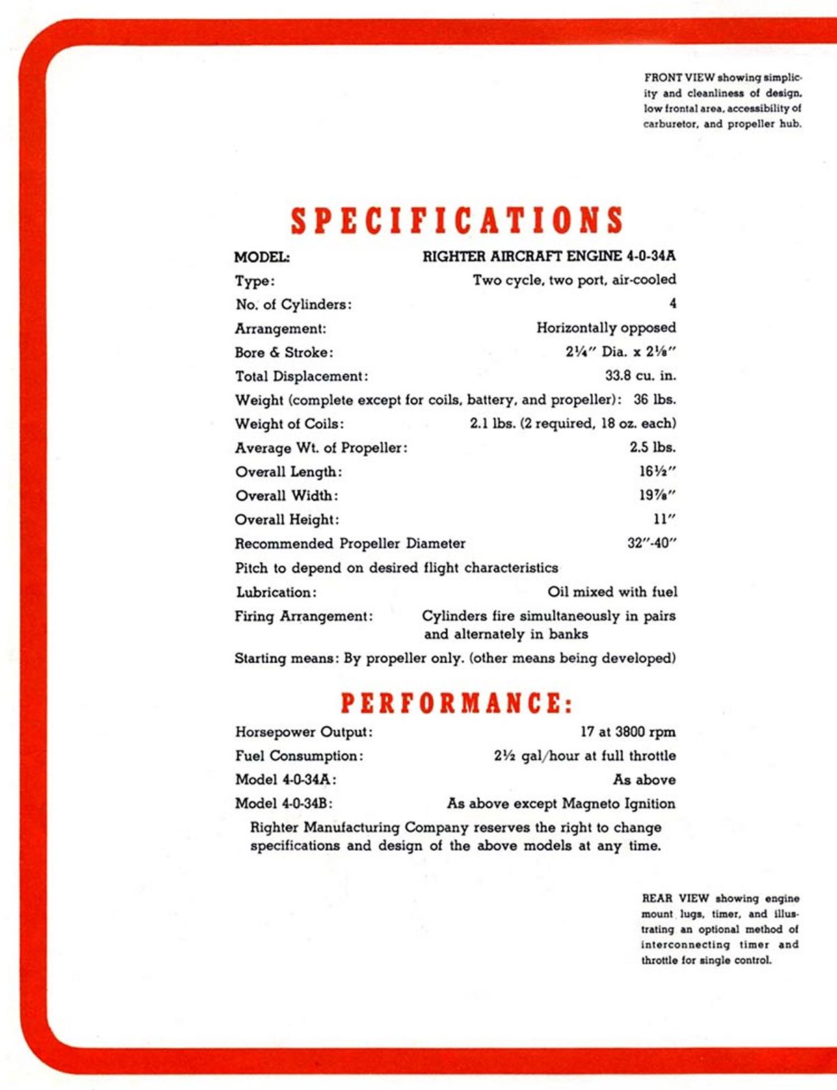
Walter Righter (1905-1982) designed and produced the 5 horsepower 2-AC-10, 6 horsepower contra-prop 2-GS-17/O-15-1, 8 horsepower O-15-3, and 20 horsepower O-45-1, two cylinder, two-cycle engines that powered the 15,000+ gunnery target drones produced during WWII. Looking towards the post-war future, Righter designed a “double” O-15-3 engine, the 4‑O‑34 (4 cylinder-opposed-34 in³) of 17 horsepower he hoped to use for self-launching gliders. |
 |
 |
 |
| Pic 1. 1944 Righter 4‑O‑34 Brochure | Pic 2. Righter 4‑O‑34 Specifications | Pic 3. 1944 Righter 4‑O‑34 Advertisement |
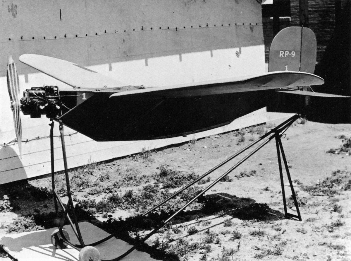
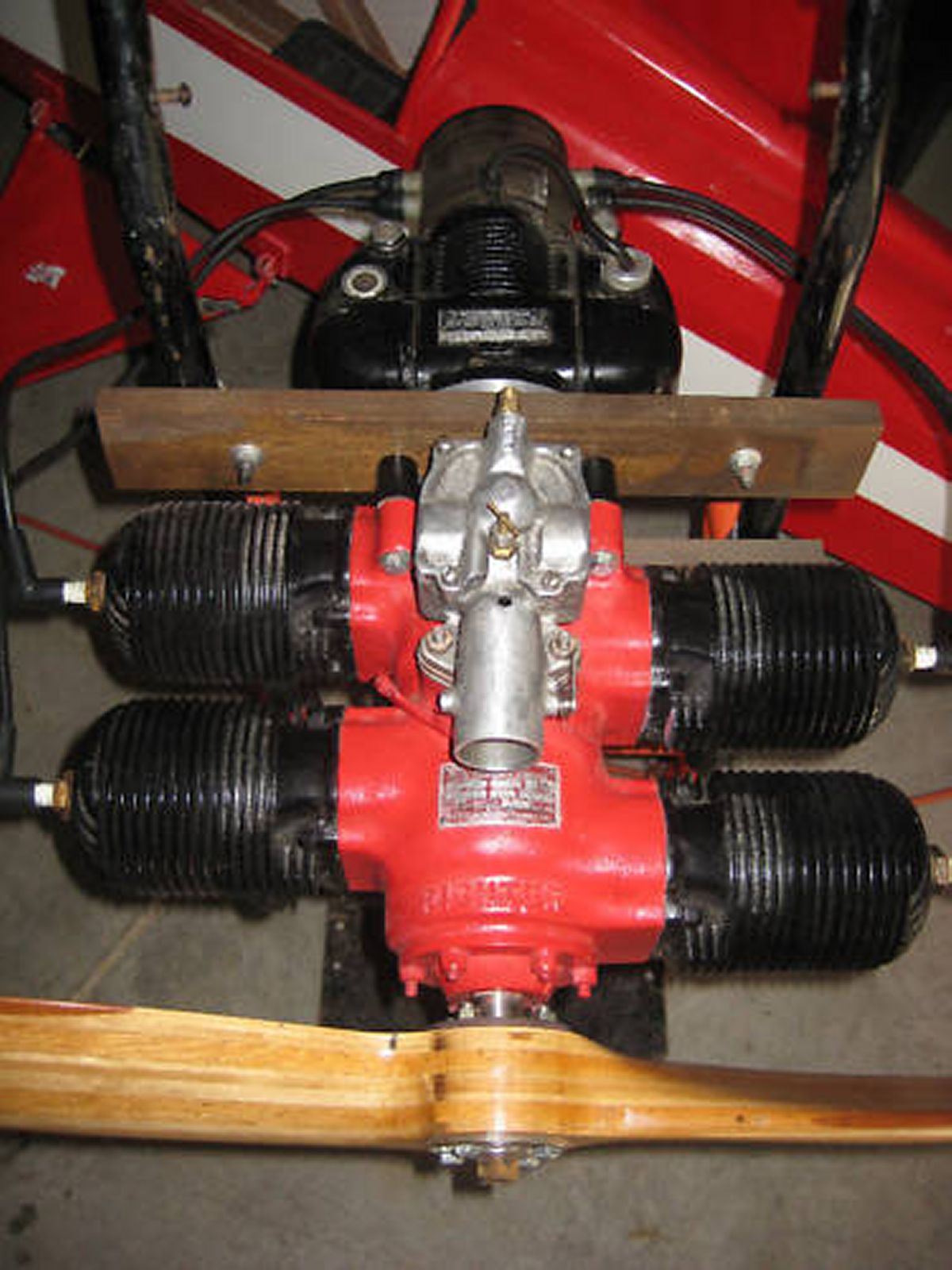
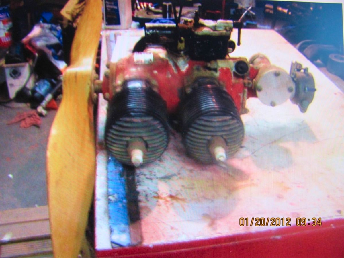
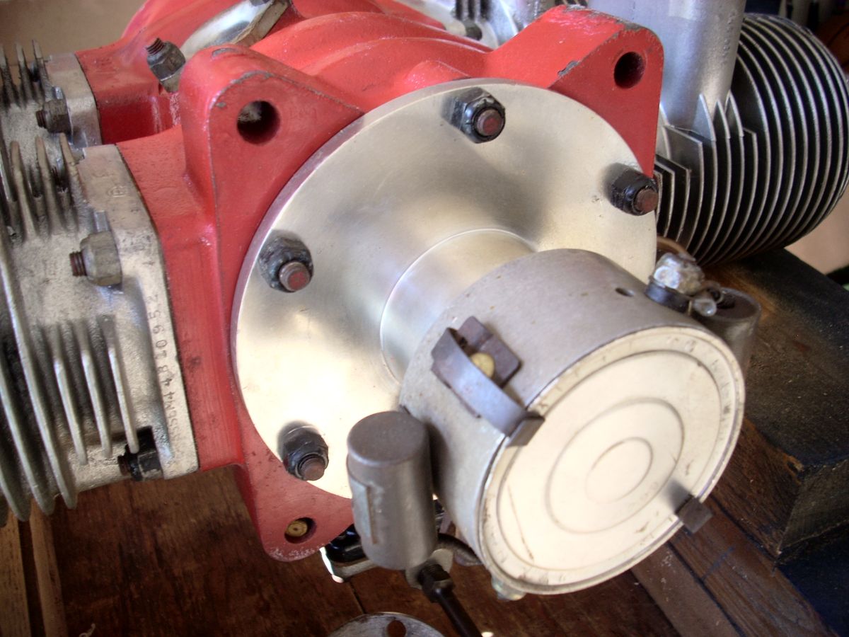
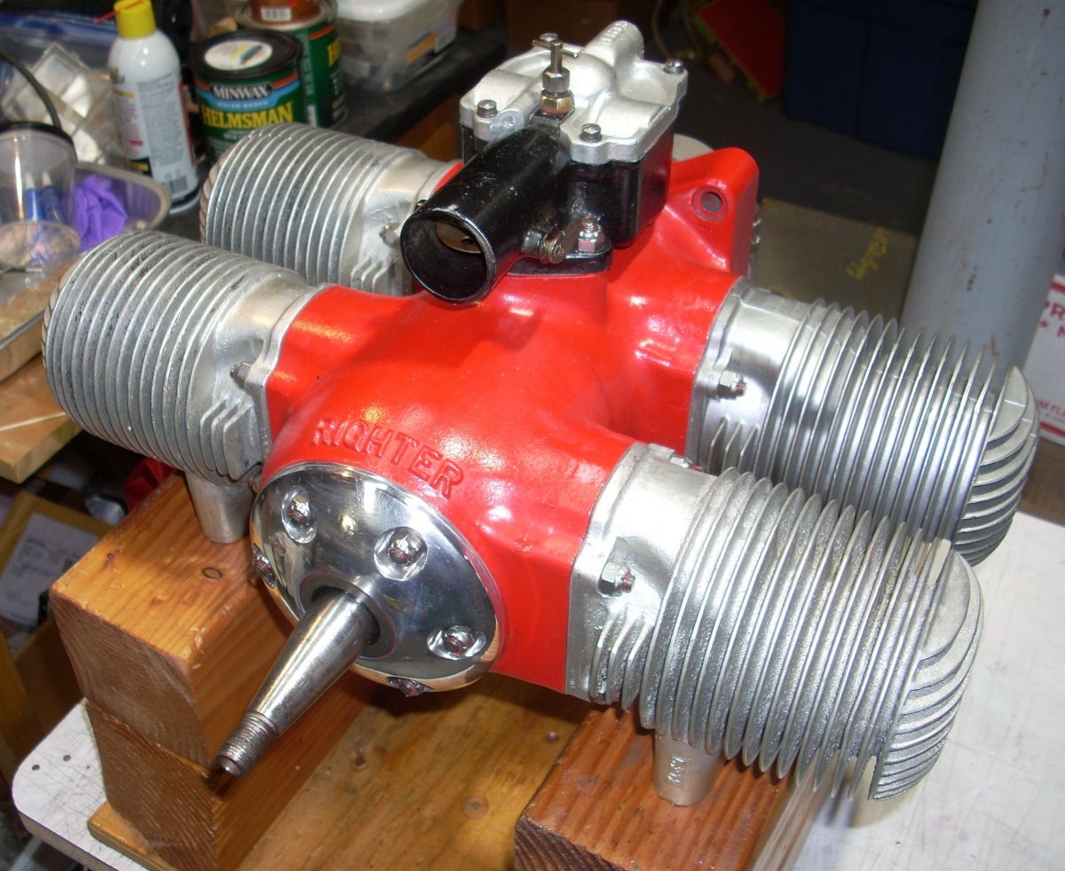
It is somewhat peculiar that Righter chose to build a 17-horsepower engine when a lighter, 20+ horsepower engine was already in production, but the WWII drone engines were designed only for use in the tractor configuration. The 4‑O‑34 had a captive thrust bearing in the nose, so it was amenable to either tractor or pusher use. Righter built only nine of the 4‑O‑34 engines, and these were variously configured with unthrottled carburetors on the top of the engine for drone use (Pic 4), throttled carburetors on the bottom linked to the ignition advance “timer” (Pic 5), a “B” model with magneto ignition (Pic 6), and at least one variant with an angle drive that mounted a pull-starter assembly (Pic 7). At least six 4‑O‑34 engines are known to survive, one of which I am now restoring to running condition. (Pic 8)
 |
 |
 |
 |
 |
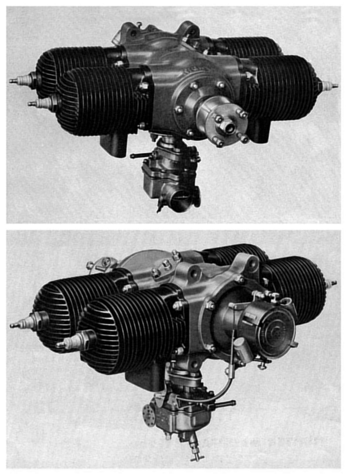
| Pic 4. 4‑O‑34 Mounted in the One-Off Radioplane RP-9 Radio Controlled Aerial Gunnery Target | Pic 5. The Production 4‑O‑34A Engine. Note the ventral carburetor with interlinkage to control the spark advance timer and the die-cast front and rear covers. |
Pic 6. Righter 4‑O‑34B with Magneto | Pic 7. Righter 4‑O‑34 Internet image shows the unthrottled dorsal carburetor and extended rear cover containing an angle drive, likely for a tachometer and/or pull starter. | Pic 8. Righter 4‑O‑34A As Received by the Author in 2015. Front cover shape is similar to that on the 4‑O‑34 engine brochure. There is no evidence that this engine ever had a data plate. |
 |
 |
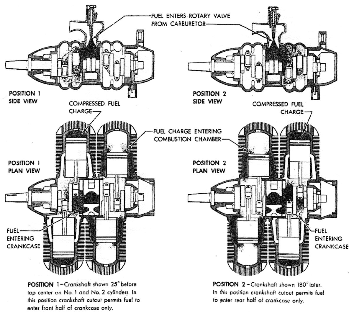 |
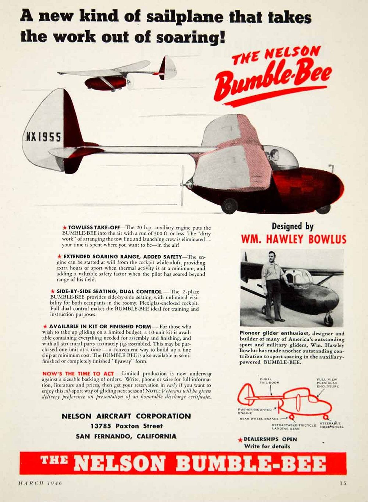
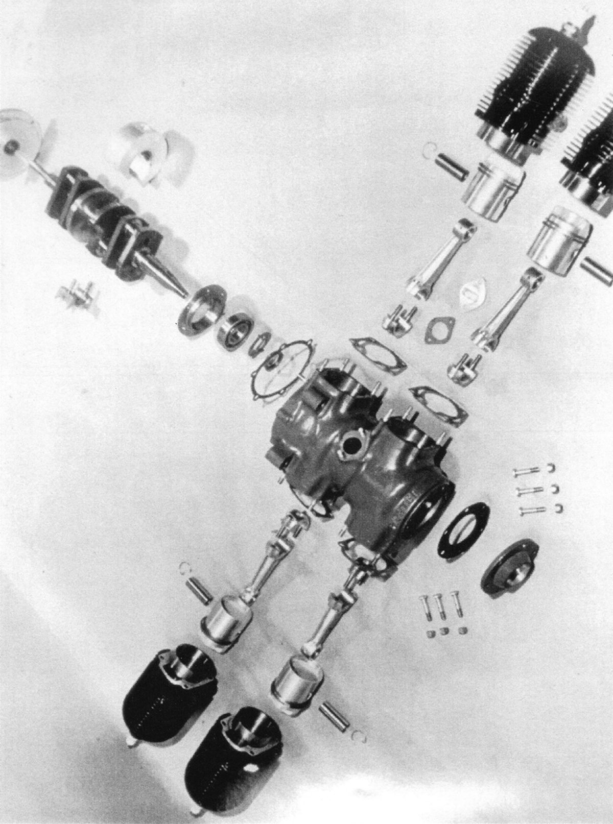
| Pic 9. The prototype Nelson-Bowlus Bumble Bee / BB-1, NX1955, successfully, but marginally, powered manned flight with the 17 horsepower Righter 4‑O‑34 engine. This qualifies the 4‑O‑34 as an aircraft engine. | Pic 10. Exploded 4‑O‑34. Note the center body assembly in the crankshaft center and the pie-shaped crank cheek cut-outs that time the fuel/air/oil mixture distribution to the fore and aft crankcase halves. | Pic 10a. McCulloch 0-100 Engine Operational Schematic. The 4‑O‑34 operates on the same principal. |
The 4‑O‑34 did power manned flight in the Nelson-Bowlus BB‑1/Dragonfly (Pic 9) but only barely so as shown in the high-quality period film (video link). Ted Nelson went on to design and build two-cycle, four-cylinder engines of 25 horsepower (H-44), 28 horsepower (H-49), and 40 horsepower (H-59) to improve the performance of the aircraft, but only eight Dragonfly aircraft were produced.
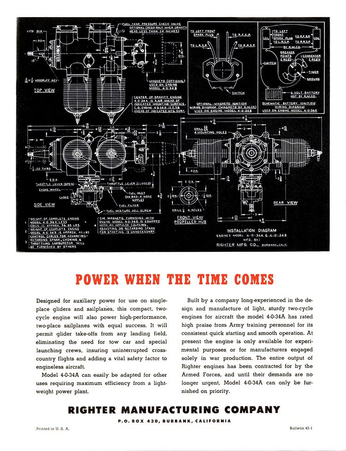
The 4‑O‑34 used the existing O-15-3 pistons, cylinders, and connecting rods in the two-cycle, four-cylinder configuration. The forward cylinders fired simultaneously, and then 180° later, the aft cylinders would fire simultaneously. The fore and aft crankcases are fed by single carburetor mounted in the center of the engine. The carb feeds a solid cylindrical “divider” center body in the middle of the engine. The rearmost crank cheek of the fore cylinders, and the foremost crank cheek of the aft cylinders, are shaped to act as rotary valves, sealing the crankcase halves from each other and supplying fuel/oil/air mixture to the respective halves at the appropriate intervals. (Pic 10) The ubiquitous, 72 horsepower McCulloch 0-100-1 drone engine (Pic 10a) operates on the same principal.
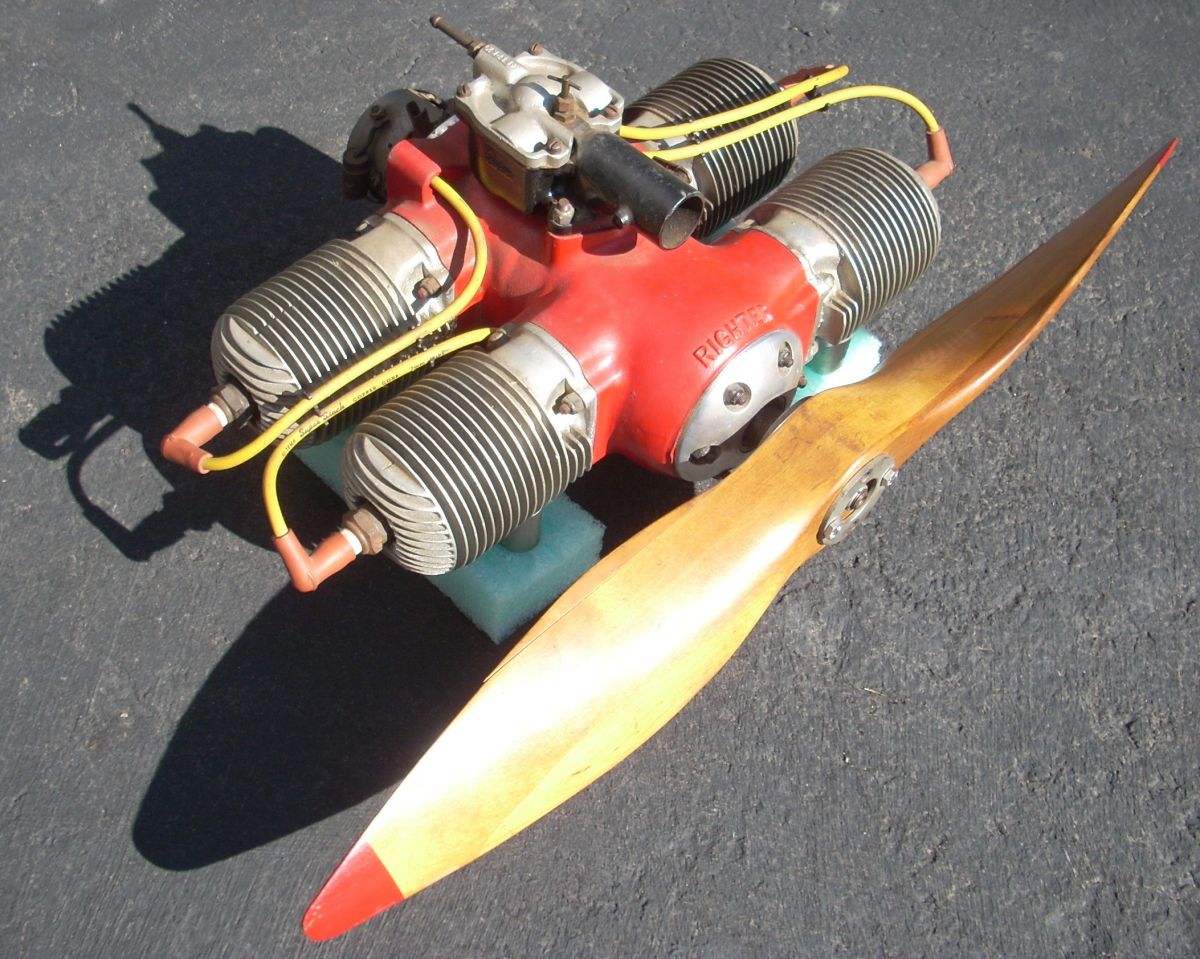
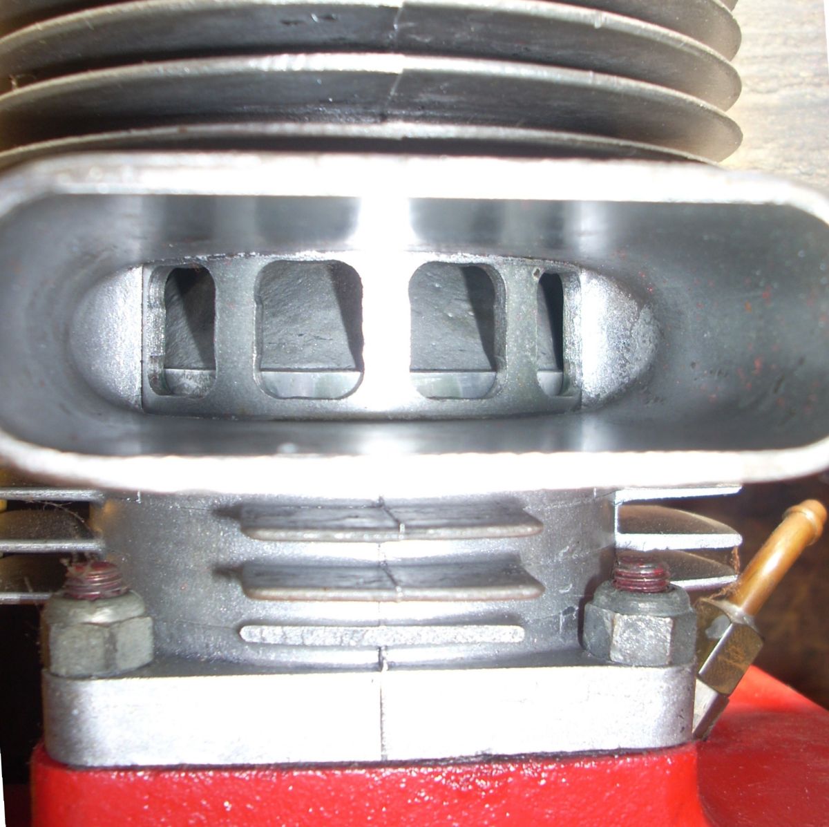
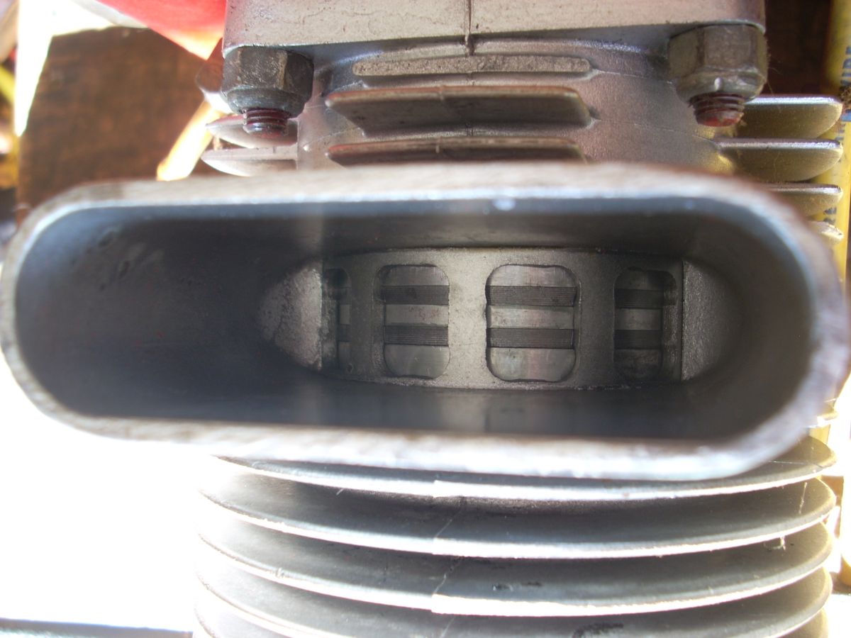
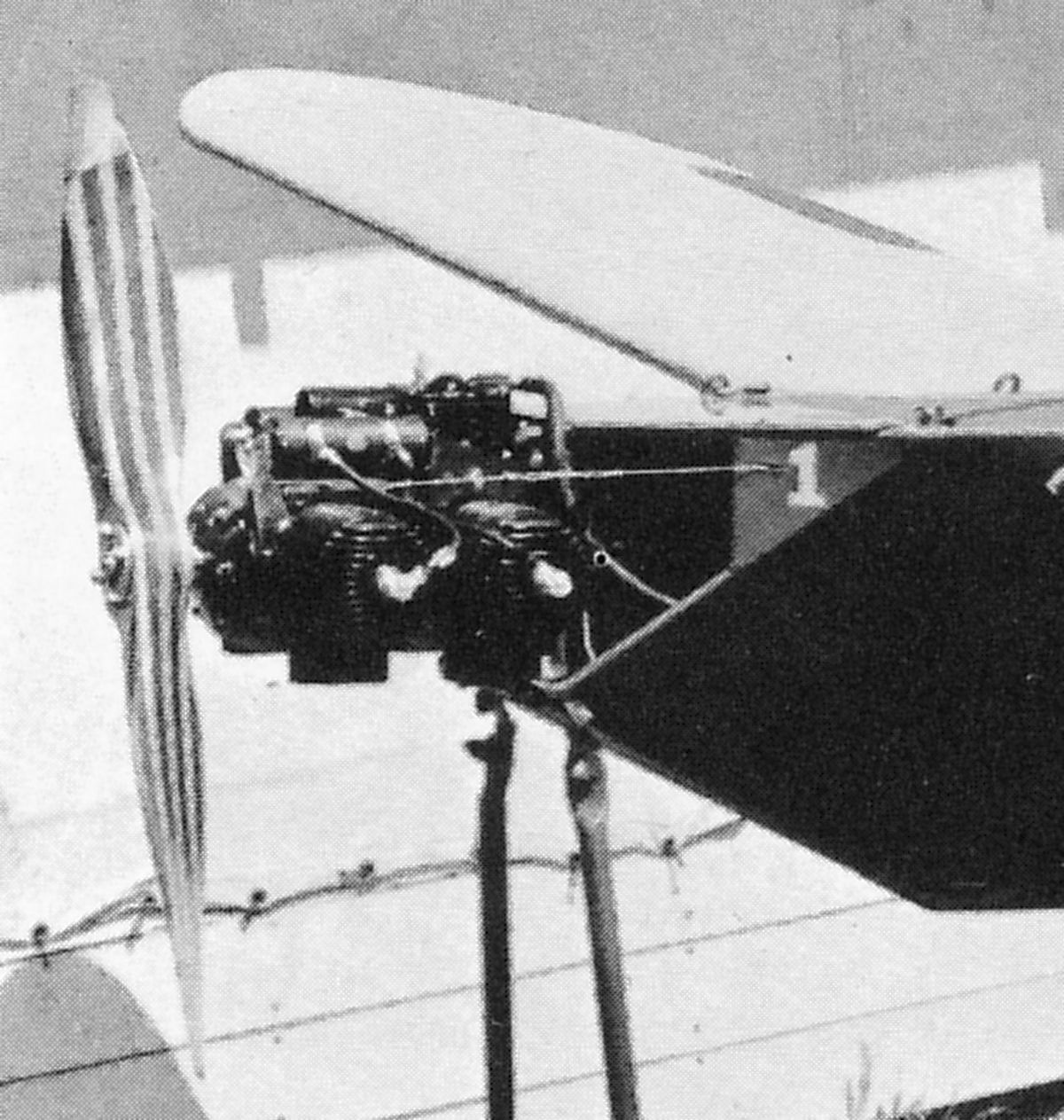
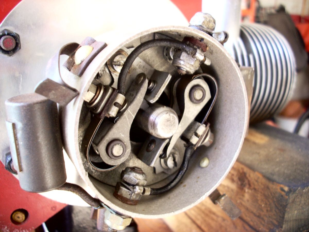
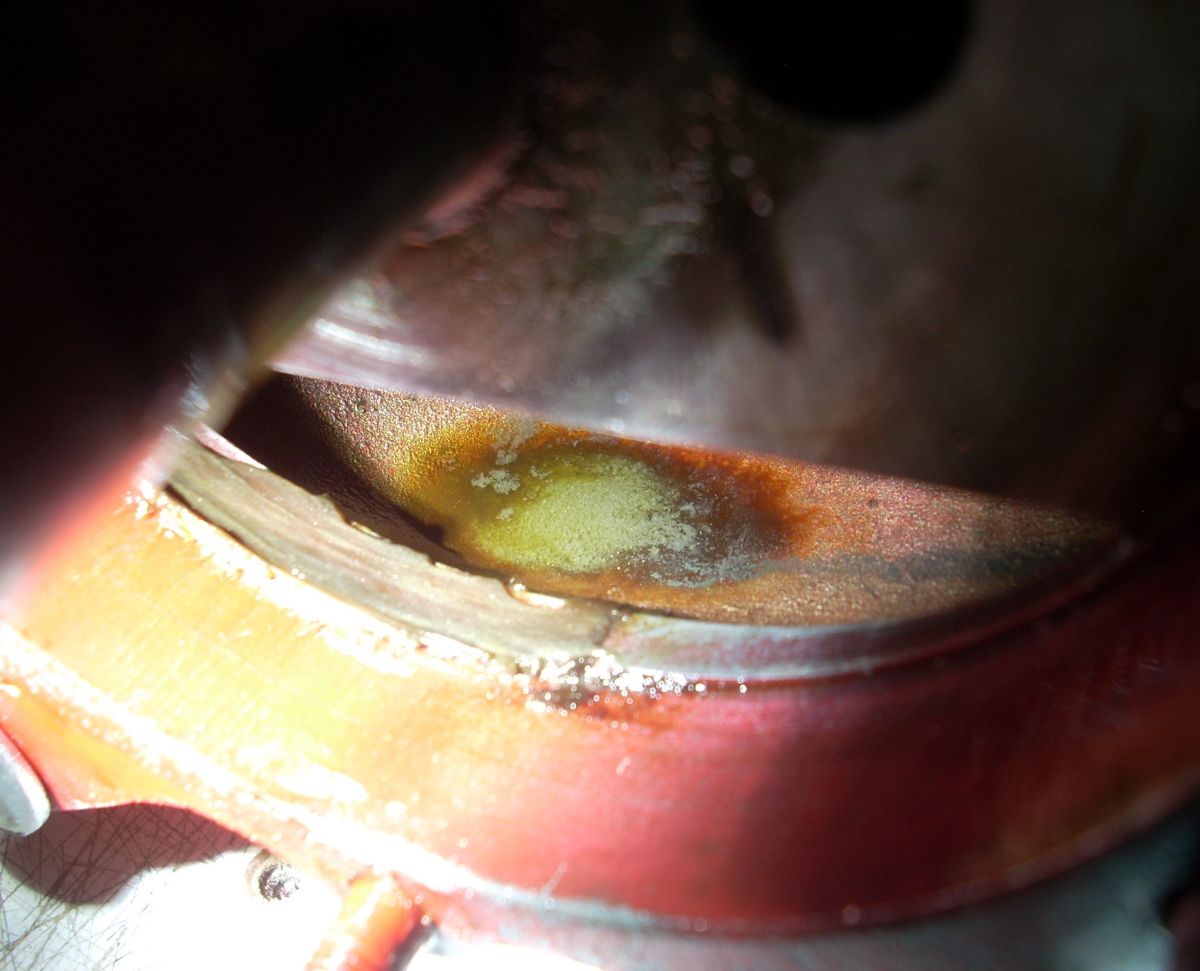
Luck favors the prepared mind, and I acquired my engine in 2015 off of Ebay. And it gets even better. The engine, which was complete, had been acquired at a government surplus sale in California by the father of the seller in 1945 and carefully stored ever since. The crankshaft rotated, and looking into the exhaust ports and at the piston crown, there was no carbon to be found. (Pic 11) The piston rings looked brand new. (Pic 12) The contours, chord, and diameter of the unique 30 inch diameter propeller, made of four laminations, matched a propeller in period photographs. (Pic 13) The inside of the dual-points ignition timer housing was spotless, and there was no corrosion to found anywhere. (Pic 14) The spark plugs were the appropriate part number 6-COM-62, and two had the solid, non-removable “aeronautical style” center post. (Pic 15)
 |
 |
 |
 |
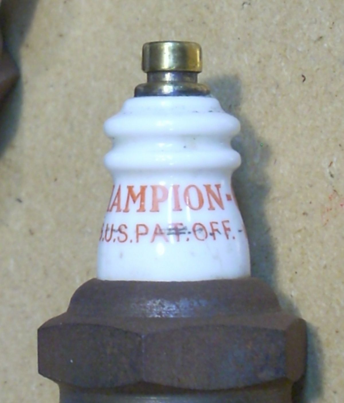 |
| Pic 11. Unblemished piston crown is visible through the 4‑O‑34 cylinder exhaust port. | Pic 12. Clean, unscuffed, and likely new piston rings visible through the 4‑O‑34 cylinder exhaust port. | Pic 13. Close-up of the 4‑O‑34 on the One-Off, 1944 Experimental RP-9 Target Drone. The front cover seems to be dome-shaped like the subject engine, and the distinctive propeller shaping is highly similar to the author’s 4‑O‑34 propeller. | Pic 14. The ignition timer has two sets of points. Each point controls a dual coil that fires two opposing cylinders simultaneously. | Pic 15. Champion 6-COM-62 spark plug with the solid center electrode post termed “aeronautical style”. Most 6-COM-62 plugs have a brass thimble screwed onto a threaded center post. |
 |
| Pic 16. 4‑O‑34 Timer; rear cover is machined from aluminum billet. |
The engine had no data plate or evidence that it ever had one. The front cover/bearing retainer in the nose was a rounded, beautifully machined single piece of aluminum. The rear cover appears to be machined from billet and is unlike any of the period photographs of the other 4‑O‑34 engines. (Pic 16) The cylinders, three of which are O-15-3 cylinders, the other from a 2-GS-17, are sandblasted natural aluminum. Occupied with other things, I shot fogging oil into every orifice, plugged all the holes, and then stored the engine under low humidity until October 2021.
There were two challenges to make the engine a safe runner. First was the need for a new propeller due to age and separation of the narrower laminations of the original propeller. The second was the absence of the impossible-to-find forged steel angled eyebolt mounting eyes.
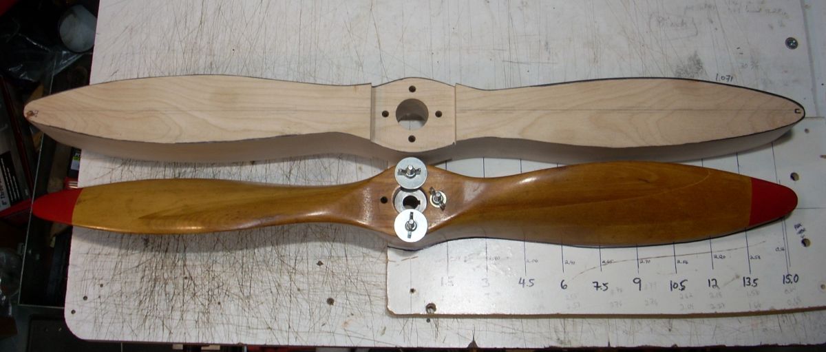
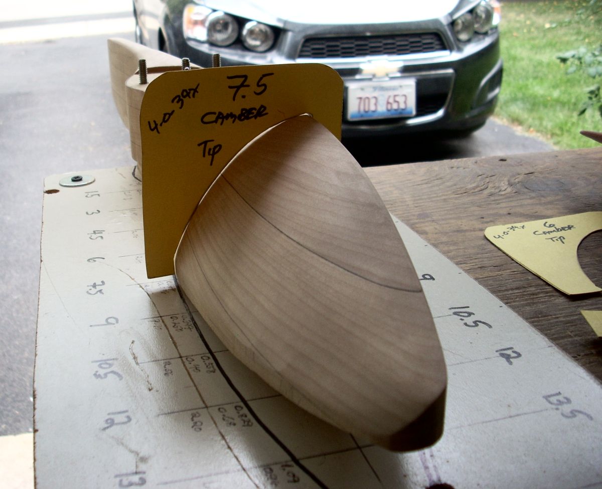
Using the original propeller as a master, I made cardboard airfoil templates at 1.5-inch stations from bore center to tip, for both the thrust (aft) and camber (fore) faces. Carefully selected white birch boards were planed to 1 inch thickness and glued together with two-part Cascophen (Rescorcinol) glue. Carving the propeller has been described in my other restorations, and it takes a long time to get it shaped, blade-matched, and balanced. But as of August 2021, Challenge #1 had been conquered. (Pics 17, 18, 19, 20)
 |
 |
 |
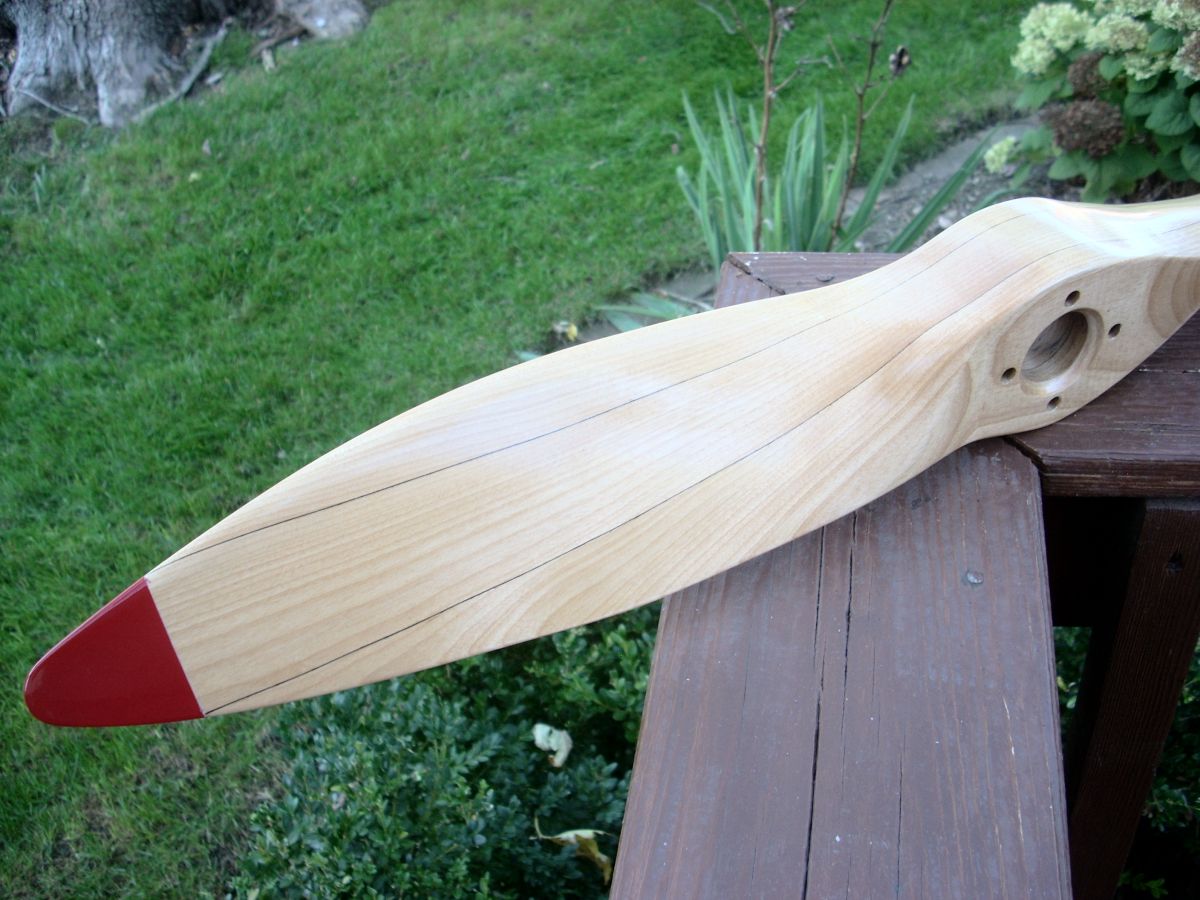 |
| Pic 17. Layout Board for 4‑O‑34 propeller. Airfoil templates are derived at each 1.5" station from the centerline. Templates will be used to guide the shaping of a new propeller for running. | Pic 18. Blank propeller shaped to planform is shown above the original prop. | Pic 19. Laborious, iterative process of shaping propeller to match the template is done primarily with a 1" vertical sander. Photo indicates the shaping is on track but too thick as the template feet need to sit flat on the board. | Pic 20. Thrust (aft) face of the completed propeller. Wood is selected for straight, parallel grain running from tip to tip. |
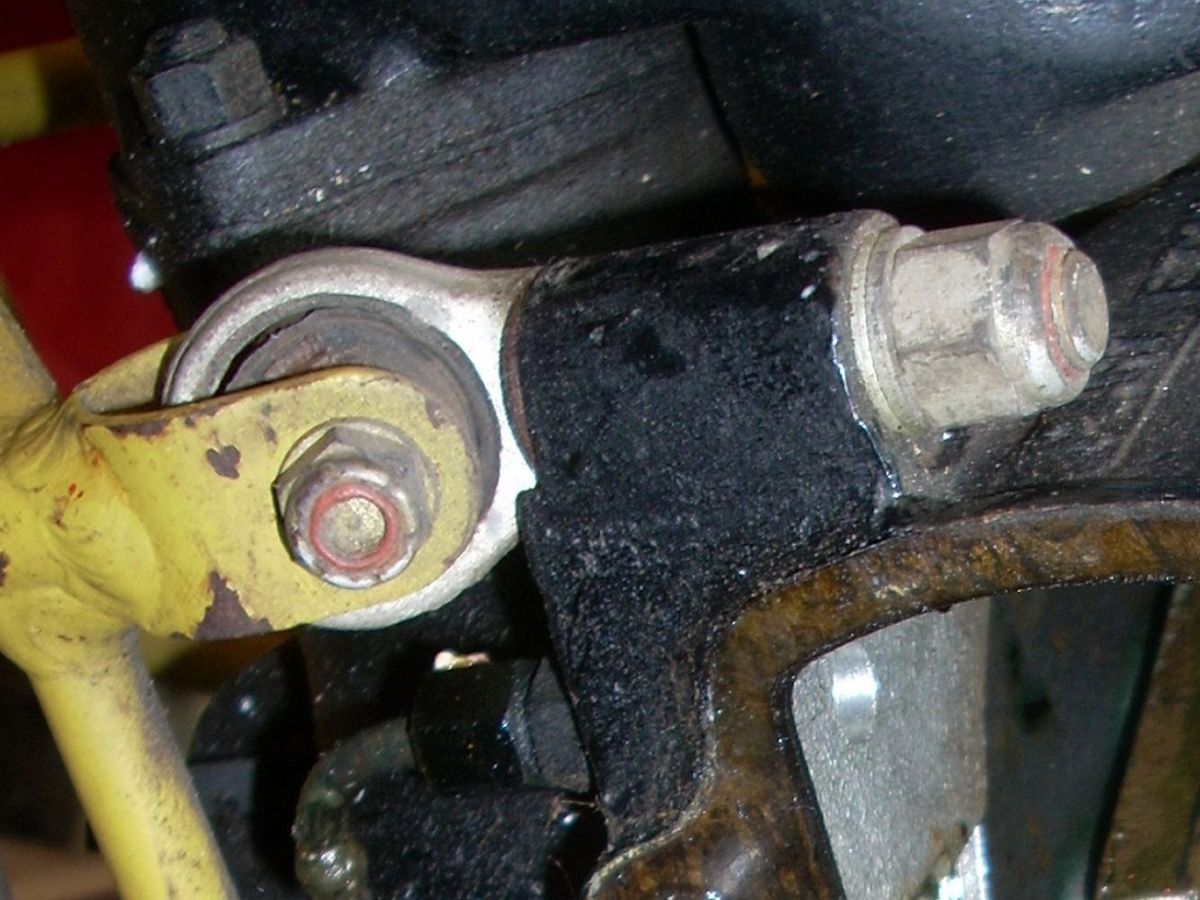
In my cache of unrestored drone engines is a 1946 Kiekhaefer 0-45-35 drone engine (35 horsepower) attached to a tube steel mount from a Globe KD4G Quail with original but decayed angled eyebolt isolation mounts. (Pic 21) Remedying the eyebolts and designing an engine mount will be in Part 2 of this story. With the runner prop underway and the forged eyebolts in hand, it was time to look harder at the engine itself.
Beyond cylinders, rods, pistons, or a second engine, there are no spare parts for a 4‑O‑34, so I needed to be sure the engine was mechanically sound. I made a cradle from threaded rod and scrap wood, then off came the front cover, rear cover, and all four cylinders. There was spectacular news as well as a few rubs. Pun intended. (Pic 22)
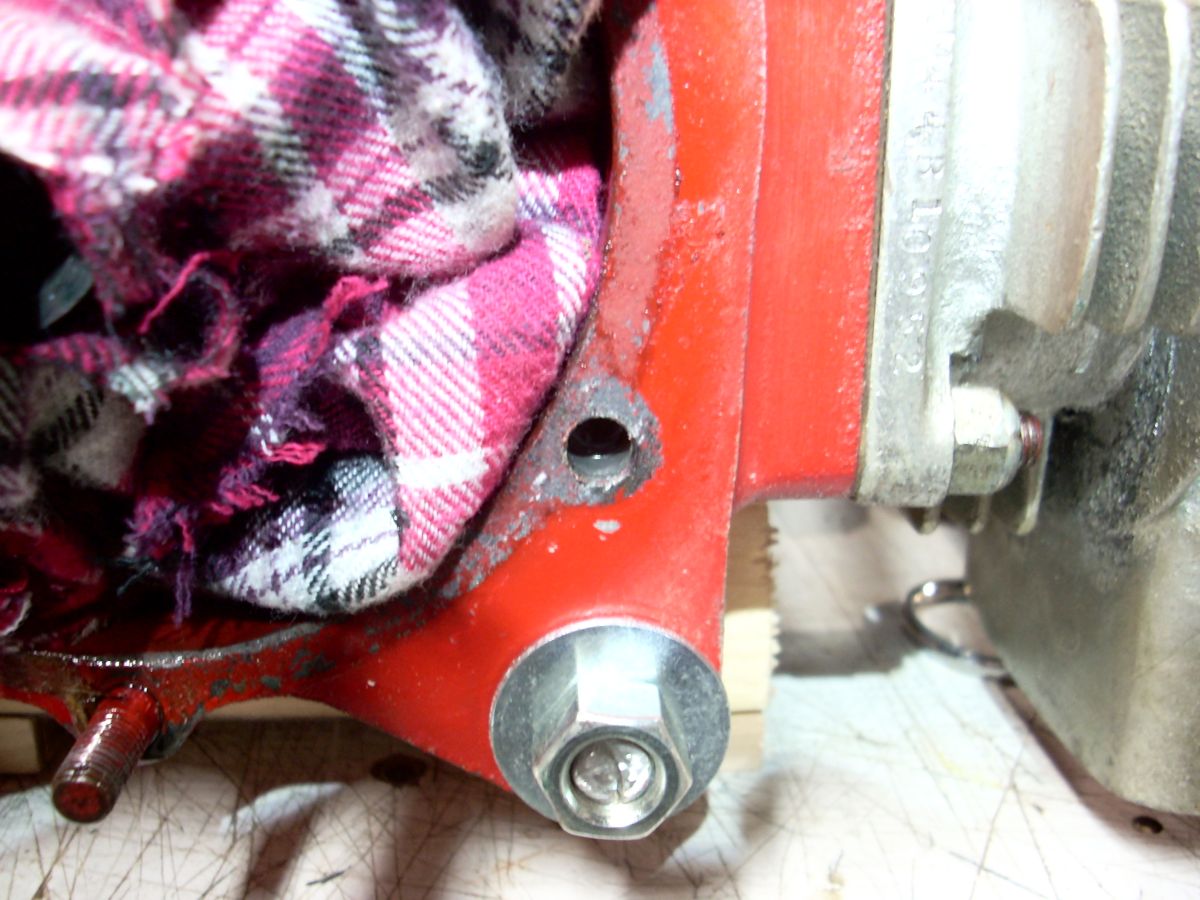
Engine Issue #1 was a stripped stud, one of six, which secured the rear cover to the crankcase. The threadless hole indicated the engine had been run. The problem was easily remedied with a Heli-Coil insert in the crankcase. (Pics 23, 24). To be honest, I bored the hole for the insert at a slight angle such that the stud now had a misaligned, no-go entry into the cover. I suspended the stud on the basement floor with nuts threaded on the opposing ends, put the shank of a half inch diameter drill bit on the grip in the middle, and whacked the shank with a handy 30-pound dumbbell. After dry test fitting, I marked the proper alignment, then threaded it in place with red Loctite. Torching some of the metal shavings confirms the crankcase to be a magnesium alloy.
 |
 |
 |
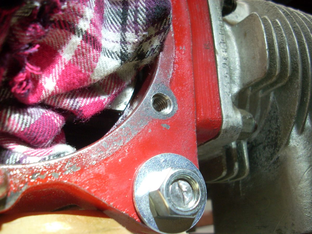 |
| Pic 21. Original forged “angled eyebolt” Lord rubber isolation engine mount used on the O-45-35 engine QEC but suitable for the 4‑O‑34. Note the delaminated rubber at the 11 o’clock position. | Pic 22. Cylinders and front bearing cover have been removed. Pistons and rings appear to be new. | Pic 23. Stripped stud hole had no evidence of threads remaining in the hole. | Pic 24. A Heli-coil was inserted in the stud hole. |
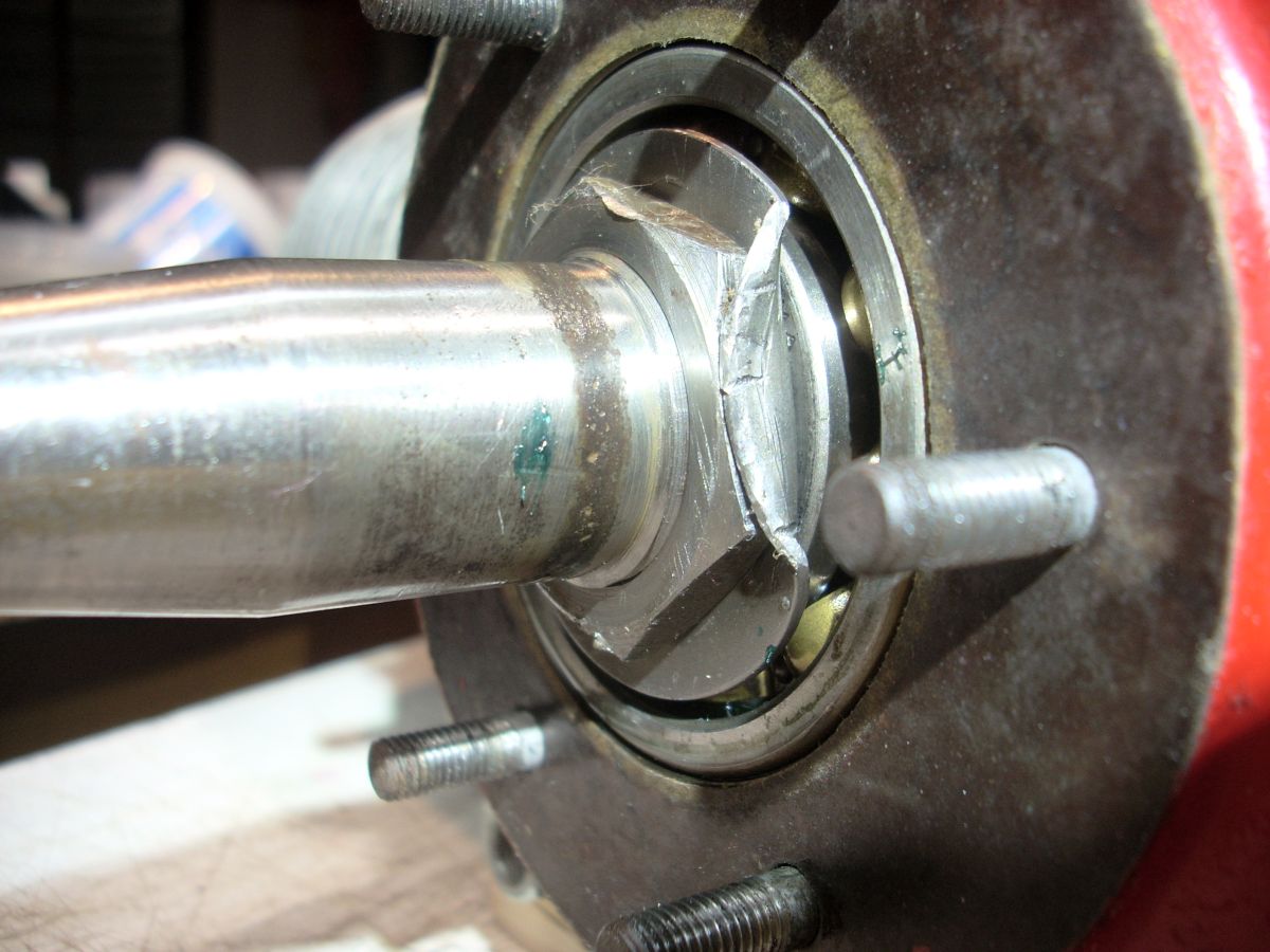
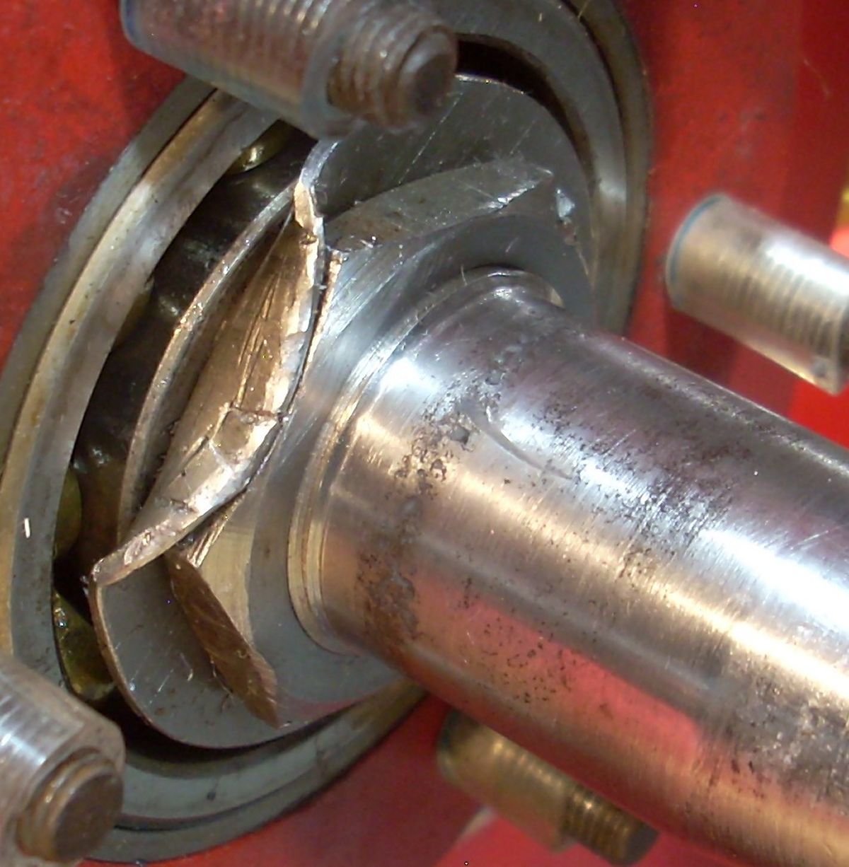
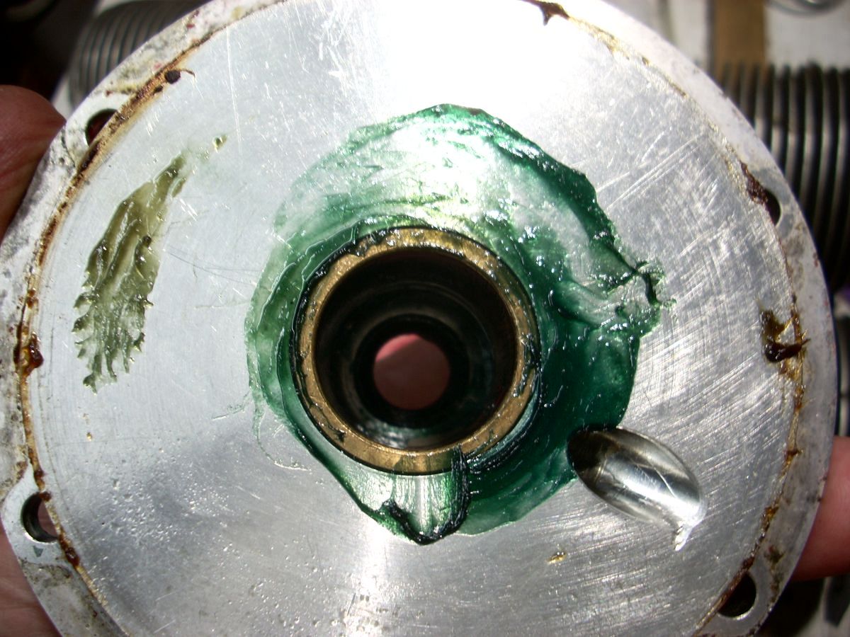
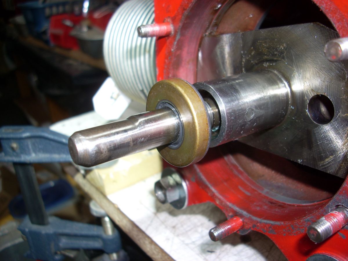
Engine Issue #2 was crankshaft pitting where the leather oil seal had collected moisture over the decades. I found this problem on another of my drone engines, but was able to get past it by using a modern oil seal that seated on clean smooth metal ahead of the pitted shaft circumference. The 4‑O‑34 was a little more complicated in that there was also an axial scar on the shaft where a new seal might run. I used a needle file to minimally dress the scar, exhaustively cleaned the shaft, and then minimally filled the pits with long-set JB Weld epoxy. I used a strip of 2000 grit wet paper, like the rag of a shoe shine boy, with light oil to level out the JB Weld. With my eyes closed I could no longer feel the pits or detect the scar with a fingernail. (Pics 25, 26, 27)
 |
 |
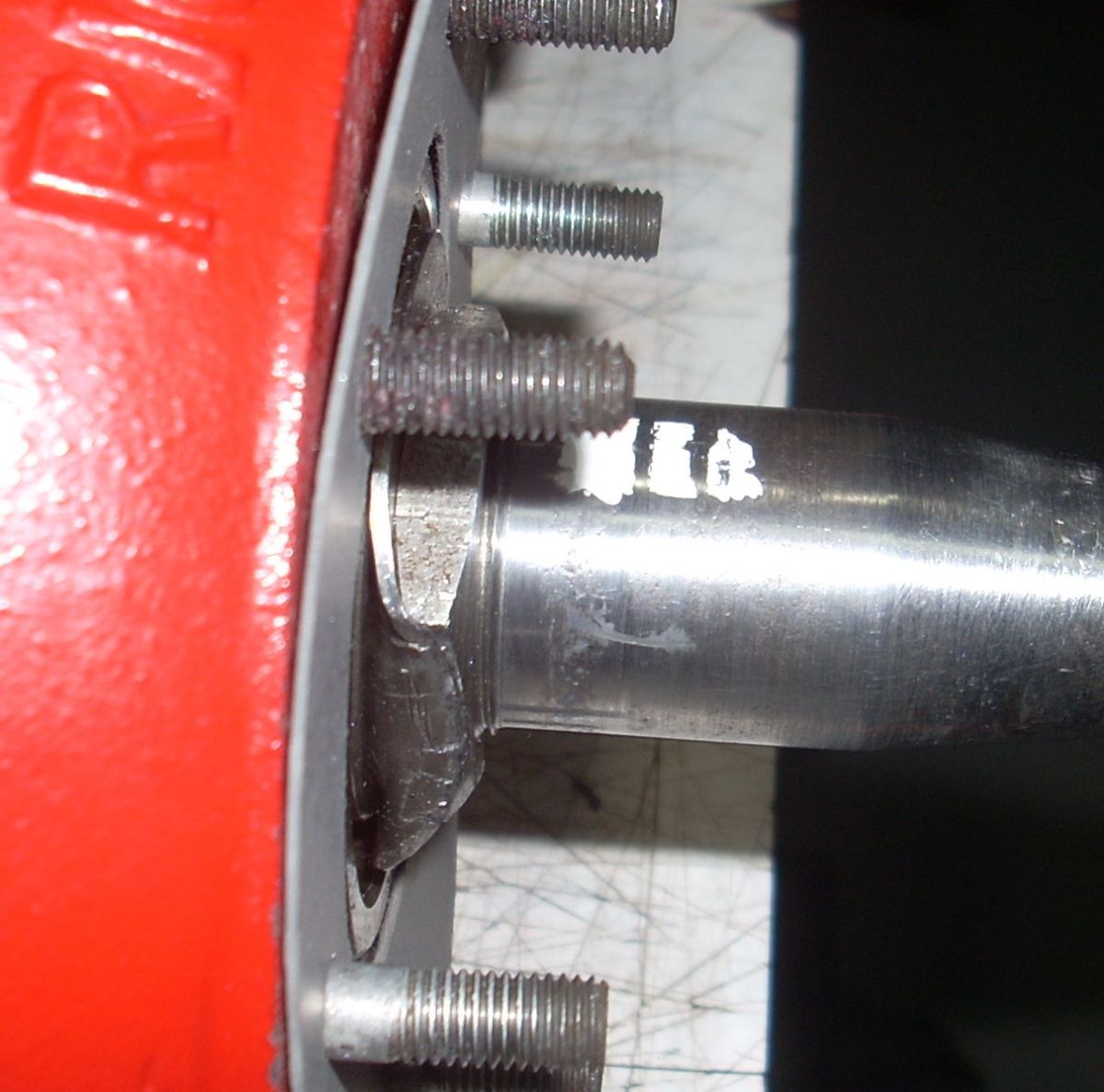 |
| Pic 25. Brown corrosion track on the pitted crankshaft where the leather gasket was seated against the shaft for decades. The large thrust ball bearing in the crankcase was found in perfect condition, perhaps new. | Pic 26. Pits and axial scar filled with epoxy and polished smooth with 2000 grit wet paper and light oil. | Pic 27. Test fit of shimmed nose cover containing the new oil seal. The two gaps in the smear of typewriter correction fluid show where the new seal contacts the shaft. Epoxy-filled scar can be seen below the white stripe. |
The nose oil seal seats in the bearing retainer cover, so to move the nose seal out onto cleaner metal, I cut a shim that duplicated the aft face of the cover from 0.063" thick 6061 aluminum sheet. A clever friend suggested I paint the shaft with white typewriter correction fluid, test fit the shimmed cover, turn the crankshaft, then remove the cover to see where the new seal runs. I was gratified to see that both seal tracks, except for the scar, ran in clean metal. (Pic 27) Issue #2 has been mastered.
 |
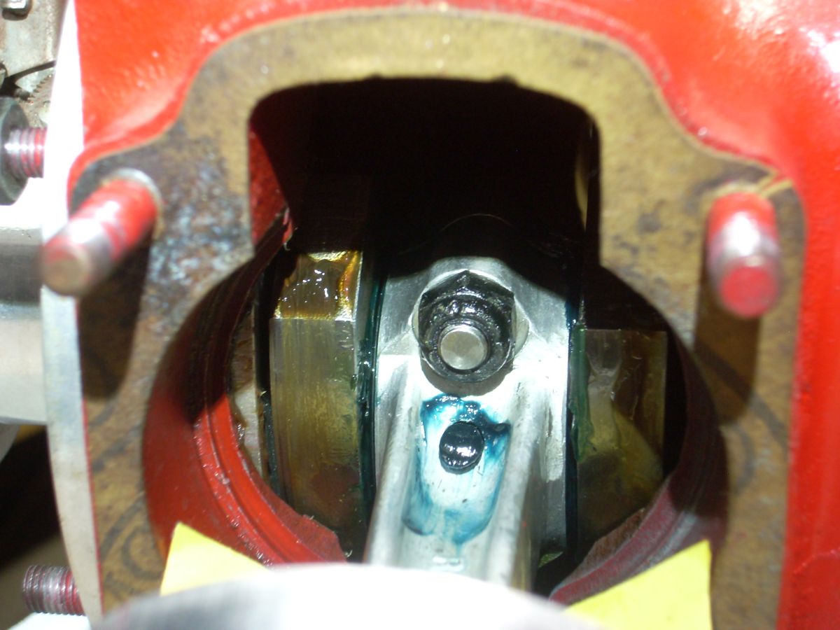 |
| Pic 28. Green assembly grease was found inside the rear cover. The angled port at 4 o’clock is vertical in the assembled engine and funnels thrown oil to the rear sleeve bearing when the engine is running. | Pic 29. Green assembly grease was found packing the connecting rod big end. The hole for lubricating the rod bearing, packed with green grease, is visible below the rod cap nut. |
Engine Issue #3 was resistance to crankshaft rotation but only through a specific 30° of crankshaft arc. The front cover was off and I removed the pressure tap from the rear half of the crankcase to open the entire crankcase to ambient air, reducing pumping resistance. There was no improvement. Then I removed the cylinders to eliminate piston drag. I found the pistons and rings were brand new, the cylinders freshly honed, all four measured the spec 2.250 ± 0.002" diameter, and there were trace remnants of carbon in the very clean heads of the cylinders. But alas, no improvement in running drag was achieved.
I figured if the un-sourceable crankshaft was bent, there would be resistance felt throughout a 360° rotation. The remaining theory was likely “tightness” in the close tolerances between the crank cheek “rotary valves“ and the stationary aluminum center body divider.
At this point I need to point out that the inside of the engine was spotless when I opened it up, and all the bearing surfaces (big and little ends of the plain-bearing connecting rod, rear bronze sleeve bearing, nose thrust ball bearing) were packed with green assembly grease. (Pics 28, 29) So I believe the engine had been run at some point in its life, but was “professionally” restored with some new parts before it went to surplus sale in 1945. When good fortune rains, it really pours.
Convinced the engine was refurbished by skilled hands, I was reluctant to completely disassemble the engine and center body. Even if I did, and without manuals or spare parts, I’m not sure what I would or could do to reduce the break-out drag.
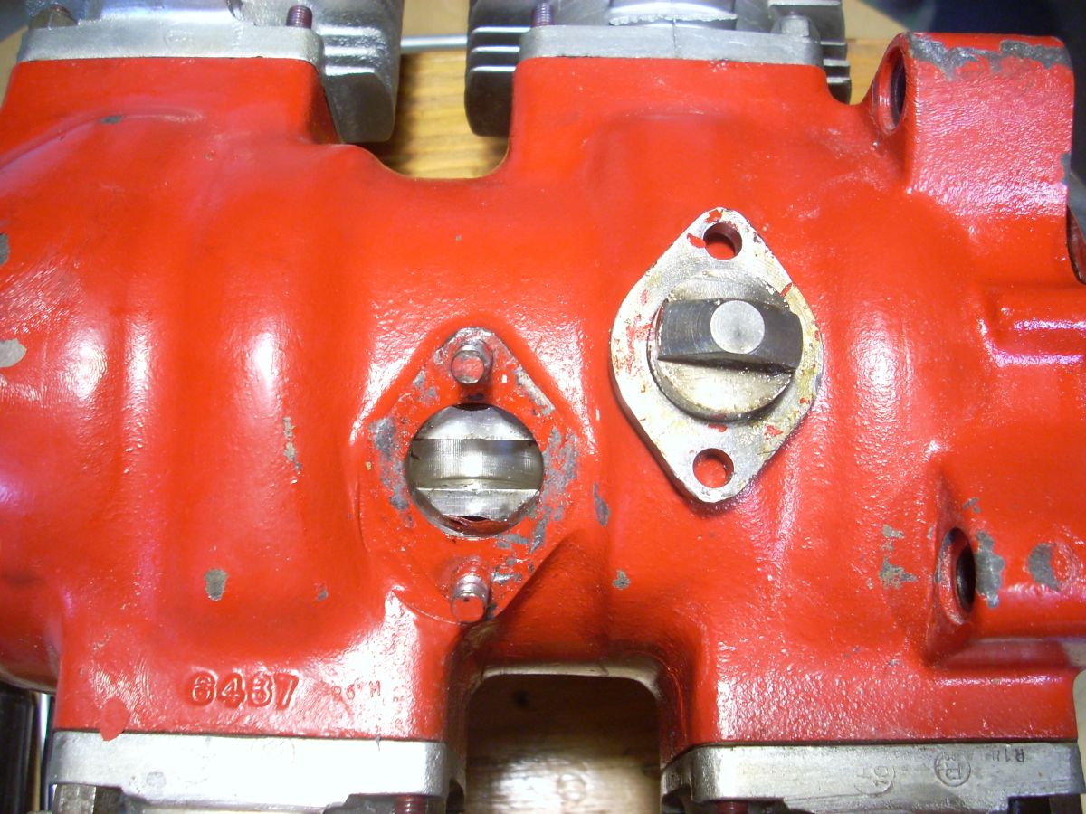
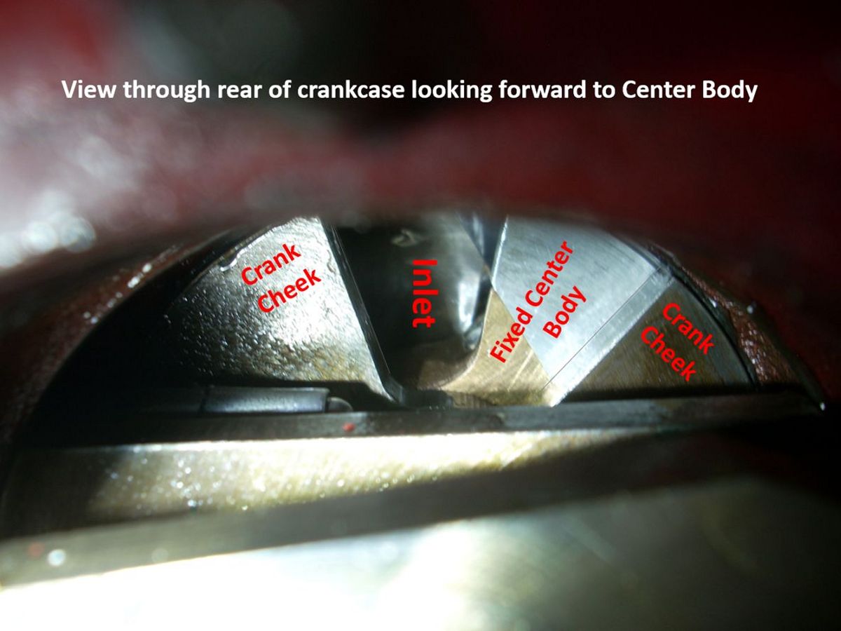
The center body has a C-shaped aluminum piece with bolted-in bronze inserts that are the main center (plain) bearing for the crankshaft. (Pic 30) The center body is located by a precision-fit, solid steel plug through the crankcase bottom. (Pic 31) Because of the center body’s function as the stationary component of the rotary valve, there can be no crankshaft end play, so machining and fitting of this component is critical to performance and longevity. (Pic 32) It was then that I decided to just break the engine in by hand.
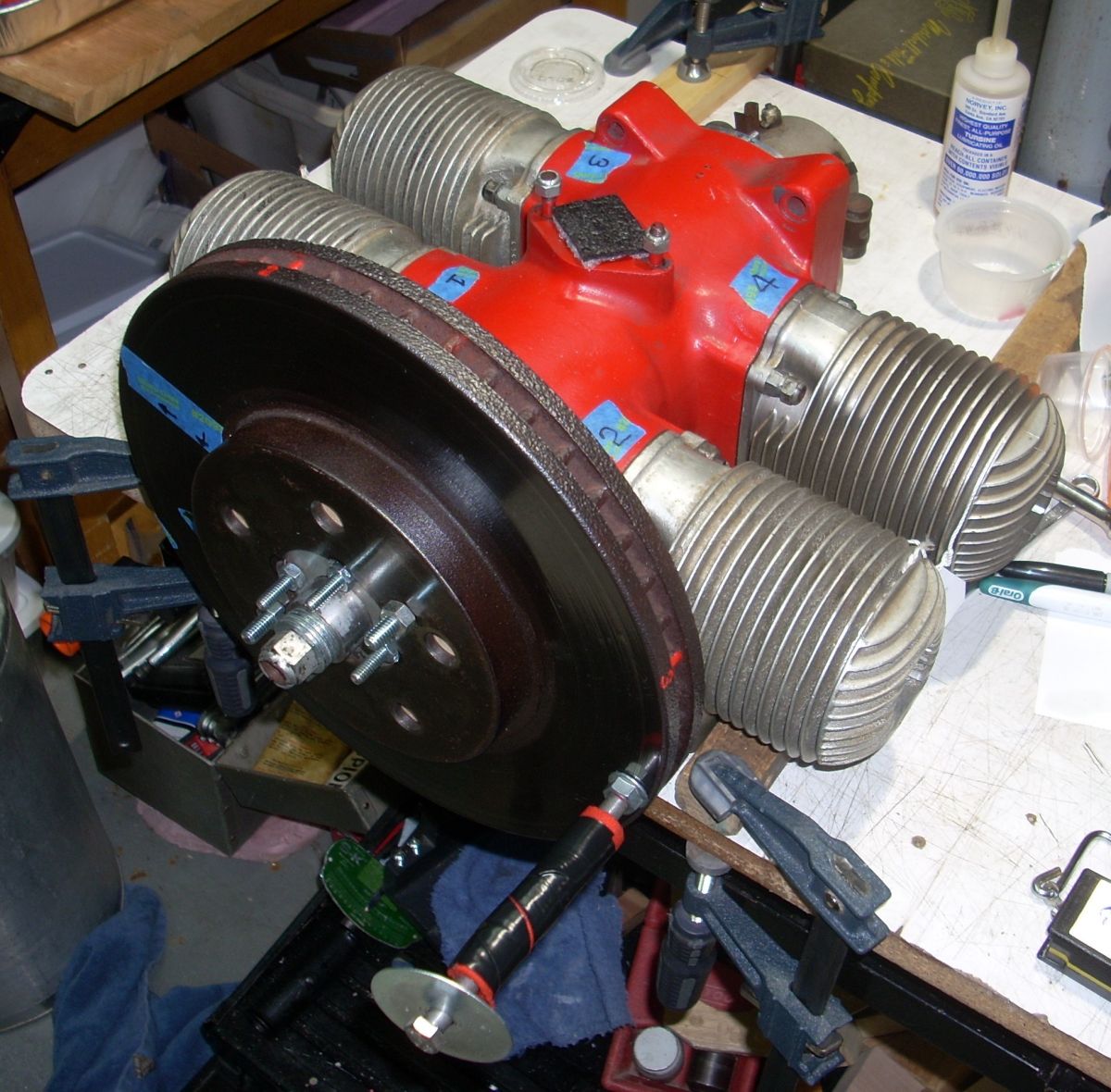
I obtained a 17.4-lb scrap disc brake rotor, fabricated a ½ inch plywood adapter to mate it to the prop hub, and sleeved a long bolt as a crank handle. (Pic 33) I put the cylinders back on, lubed the bores, and left the spark plug holes open. I could observe the crank cheeks as they ran on the center body through the carburetor port and kept everything swimming in oil. (Pic 34) I clamped the engine to the workbench and cranked. For two weeks.
 |
 |
 |
 |
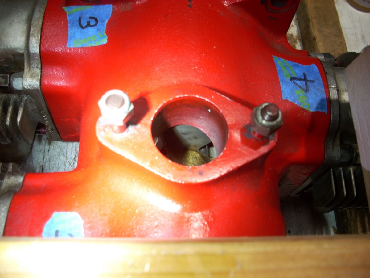 |
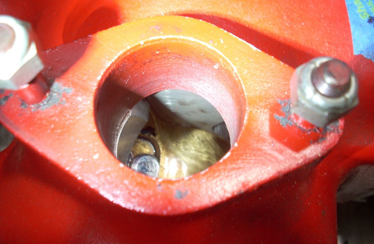
| Pic 30. The C-shaped aluminum center body can bee seen at the image right , the bronze bearing cap opposed on the bottom. The pie-shaped crank cheek cutout (rotary valve) for the forward crankcase can be seen at the 10 o’clock to 12 o’clock position. | Pic 31. The steel plug that secures the center body in place. The shaping of the tongue prevents both rotation of the center body as well as translational movement fore or aft. | Pic 32. View of the Center Body Looking Forward from Aft. The crank is rotating clockwise and the crank cheek rotary valve is open, allowing the ascending pistons to pull air/fuel/oil into the rear crankcase through the open inlet. Fore of the crank cheek, the stationary center body with the bronze insert can be seen. | Pic 33. Hand-driven flywheel used to break in the 4‑O‑34. It’s only crazy if it doesn’t work. | Pic 34. Looking Through the Carb Deck into the Center Body. A few shiny spots can be seen on the crank cheek. The rotary valve is shown partially open as it rotates counterclockwise towards fully open in this view. |
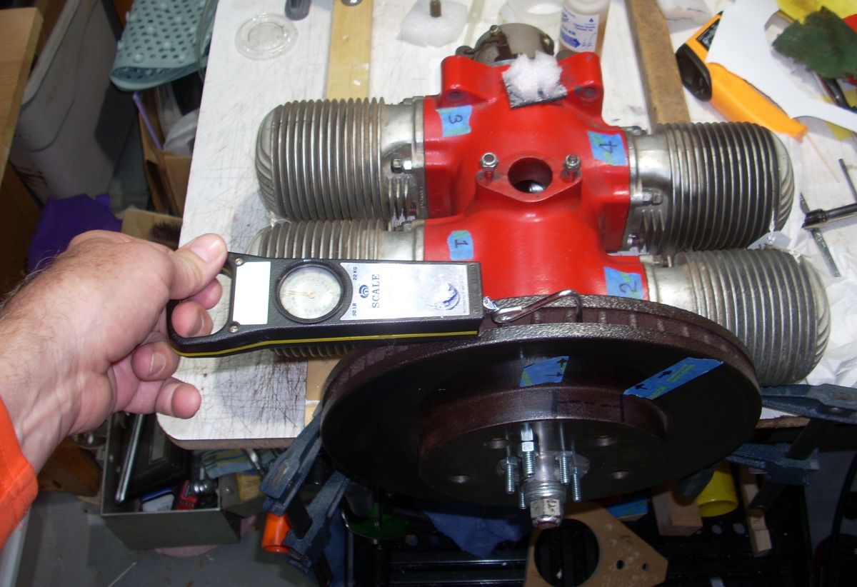
I could see the oil pooling on the center body, and before long it was picking up micro particles of aluminum. Progress! In my cranking boredom I decided to use a fish spring scale pulling on the radial vents in the brake rotor to measure the breakout forces at the stickiest point, then three additional points 90° apart. (Pic 35) I logged these crude values to quantify progress.
I eventually found small areas on the crank cheeks that were shinier than they started out to be, so I figured that was where the rubs were occurring. (Pic 36) I glued some 1500 wet paper onto long handled cotton swabs and went after those shiny spots. More progress as the highest breakout force was declining. Eventually, the breakout forces stabilized and I decided that was the best I could do. Some breakout drag remained over the troublesome 30°, but running drag was now minimal. Starting the engine might take some work, but I was confident that once running, it would be fine.
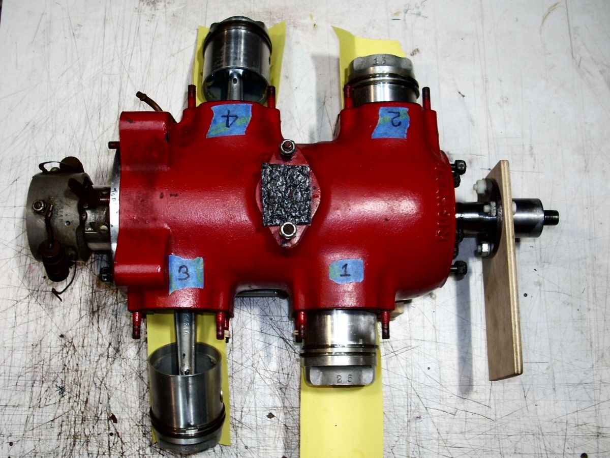
I took the cylinders and rear cover off to find very fine aluminum particles in the run-in oil pooled in the crankcase. (Pic 37) I thoroughly cleaned the inside of the engine, cylinders, and pistons, oiled everything, cut new gaskets using the originals as templates, polished the front and rear covers, installed modern oil seals fore and aft, and buttoned the engine up with new stainless steel MS20365-428 fiber nuts on the exterior studs. The blue tape I used to designate the cylinder position pulled the original red paint off the plated crankcase, but a 50/50 mix of red and dark red hobby paint made a perfect match to disguise the stupidity. (Pics 38, 39)
 |
 |
 |
 |
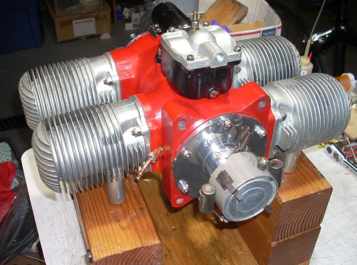 |
| Pic 35. Spring scale hooked into rotor vent measures the break out force required to rotate the crankshaft. Blue tape on rotor indicates the arc of highest resistance. | Pic 36. Shiny spots on the crank cheek rotary valve indicated where there was interference between the cheek and the center body. These spots were dressed with 1500 grit paper and light oil. | Pic 37. Flocculated aluminum in oil pooled at the bottom of the crankcase. | Pic 38. Restored 4‑O‑34 Front View | Pic 39. Restored 4‑O‑34 Rear. Note at 12’oclock the spring loaded, tooth-and-ratchet lever for advancing the timer. |
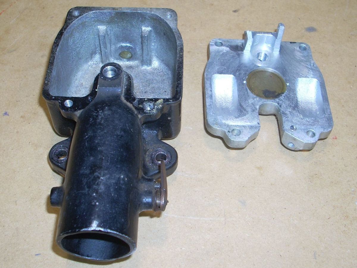
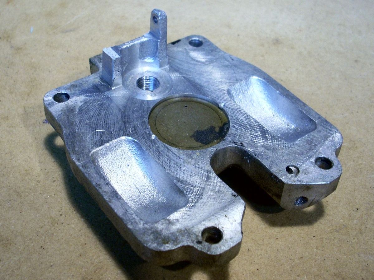
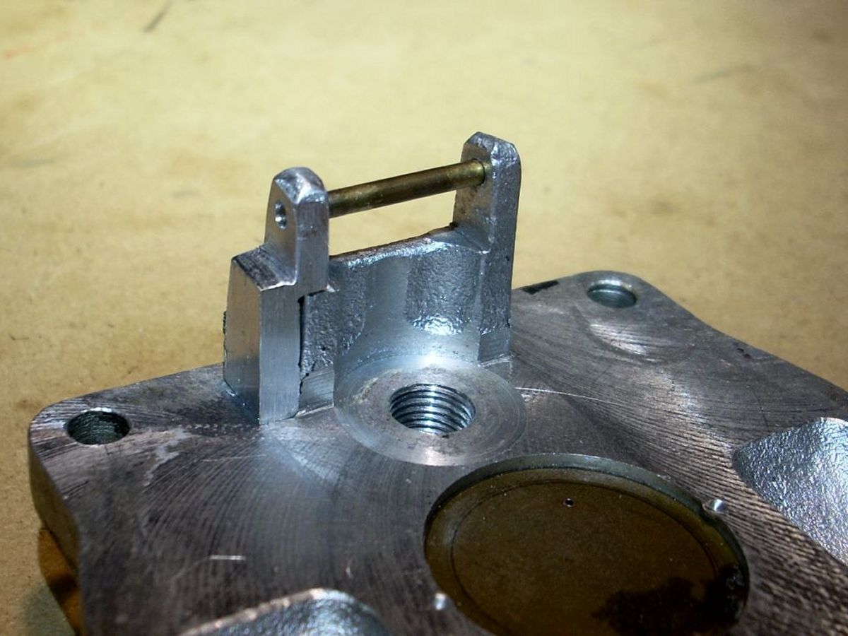
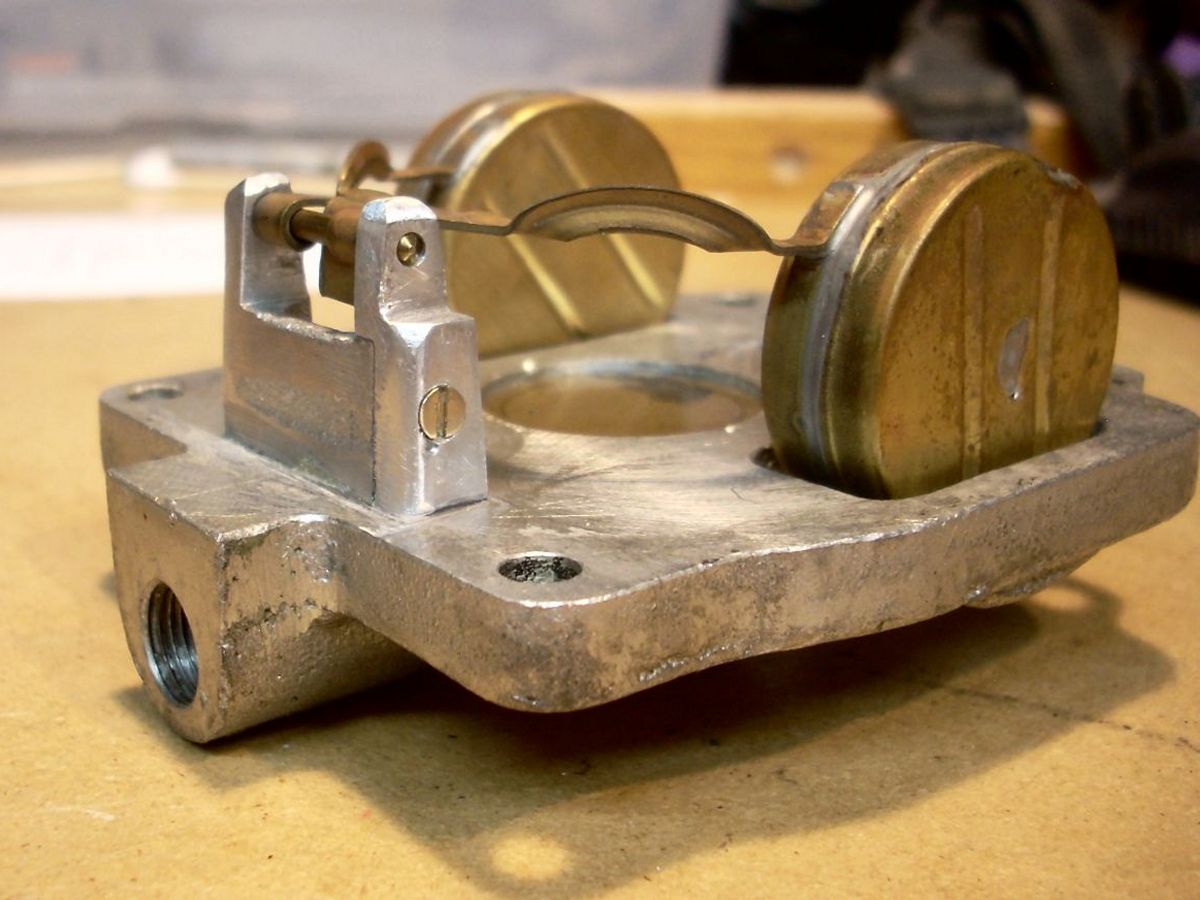
Engine Issue #4 was a broken and missing support arm for the float pivot rod in the carburetor. (Pic 40, 41) I whittled a piece of aluminum stock with a Dremel tool and needle files to mate with the stub and ultimately epoxied it in place with JB Weld. (Pic 42) Next I bored, tapped, and countersunk a hole through the arm and into the base aluminum for a brass 2-56 screw secured with red Loctite and staked it in place. (Pic 42) When reassembling I found there was interference with the tips of the support arms and the float bowl, and I think that is what fatigued and fractured the support arm. The bowl wall is not vertical but rather has a slight draft angle, so the deeper you go, the narrower the bowl gets. I used a ball cutter on the float bowl to relieve the contact. Engine Issue #4, solved.
Timing the ignition is simple. The crankshaft tail has a single machined depression that allows the rubbing block to drop the ignition points open, charging one dual coil. (Pic 43) As the crank rotates further, the rubbing block rises out of the depression, opening the points and firing the two spark plugs. One hundred eighty degrees later, the same sequence actuates the second set of points, firing the other two cylinders. The timer is rotated to full retarded and the points adjusted to fire (open) at piston top dead center (TDC) using a 1.5-volt battery and light bulb across the points and a finger in the spark plug hole. The light should light go off when the points open and the piston hits TDC. Once started, warm, and mixture adjusted, the timer can be manually rotated to give up to 26° of spark advance, accelerating the engine. (Pic 44)
 |
 |
 |
 |
 |
| Pic 40. Carburetor body at left; bowl cover with missing post at left. The carb has a choke, but no idle jet system or throttle, thus one-speed operation. | Pic 41. Missing Other Float Pivot Post | Pic 42. Dry test fit of the replacement pivot post. My bias is to remove or modify as little of the original structure as possible to get the job done. | Pic 43. Replacement post was epoxied in place, then drilled, tapped, screwed, red Loctited, and staked in place on the float bowl cover. Although the pivot post is lightly loaded, it operates in a high vibration environment. | Pic 44. Smoothed flat spot is visible on the crankshaft tail. This acts as a “depression cam” to actuate the timer points. The new gold-colored oil seal is test fit on the shaft. The long journal for the aft crankshaft bearing can be seen behind the oil seal. |
The prop and power section have been completed as of February 2022, and I’m quite sure the world will have a running 4‑O‑34 before the 4th of July.
To be continued ...
Send mail to
![]() with questions or comments about this web site.
with questions or comments about this web site.
![]()