


WWII Gunnery Target Engine Technical Analysis
Part 5. The O-45-1 and Kiekhaefer O-45-35
by Tom Fey
Published 19 Jun 2017; Revised 21 Sep 2022
Contents
Part 1. Background and General Configuration
Part 2. The Righter 2-GS-17 (O-15-1) in Detail
Part 3. The Righter O-15-3 Engine
Part 4. Performance and Efficiency Comparison between O-15-1 and O-15-3 Engines
Part 5. The O-45-1 and Kiekhaefer O-45-35
Part 6. Performance and Efficiency Comparison between O-45-1 and O-45-35 Engines
Part 7. Conclusion
The O-45-1
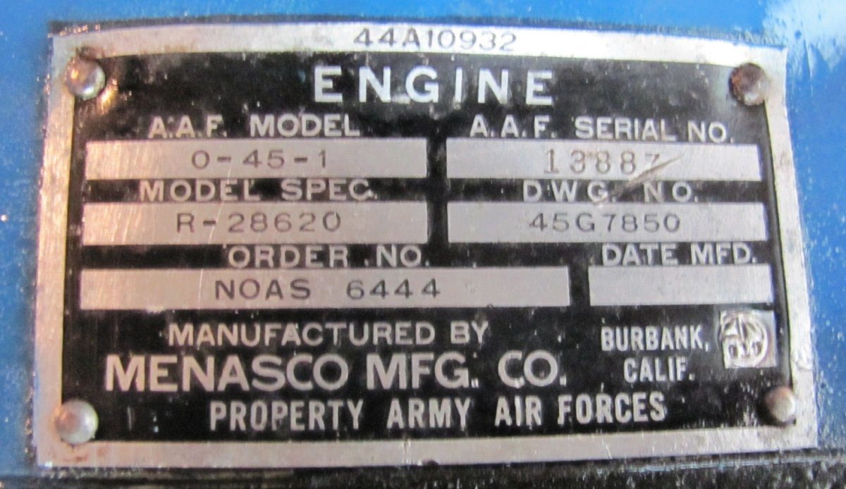
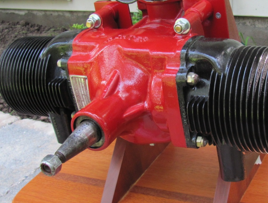
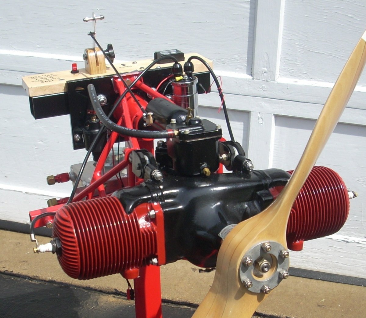
The Army soon asked Radioplane for a faster drone to better replicate a maneuvering enemy aircraft. To this end, Walter Righter designed a larger, more powerful engine, the O-45-1, to power the OQ-14/TDD-3 gunnery target aircraft that first flew in July of 1944. The 20 horsepower @ 3,650 rpm (22 hp @ 4,000 rpm) O-45-1 engine was mated to a strengthened and modified airframe very similar in appearance to that of the OQ-3, but better suited to survive the higher airspeed (140 mph versus 102 mph) and wing loading (6.7 lb/ft² versus 5.0 lb/ft²) of the OQ-14 compared of the OQ-3. Ultimately 5,204 OQ-14/TDD-3 aircraft were produced and were propelled by O-45-1 engines built by Righter, Menasco Manufacturing in Burbank, California, and Kiekhaefer in Cedarburg, Wisconsin. The Menasco O-45-1 (blue crankcase, black cylinders, "Menasco" cast in the crankcase top) is the rarest of the survivors and has the data plate riveted vertically below the starboard cylinder base. Righter O-45-1 engines (red crankcase with black cylinders, "Righter" cast into the crankcase top) are fairly common and have the data plate located at the starboard cylinder base. The Kiekhaefer O-45-1 is the most common, should be painted all black, with the data plate on the curved crankcase nose. Menasco and Righter O-45-1 engines appear to have been assigned to the Army Air Forces while the Kiekhaefer O-45-1 engines were assigned to the United States Navy.
None of the surviving Menasco or Righter 0-45-1 data plates have information stamped in the date of manufacture box. However, some of the Kiekhaefer 0-45-1 engines have the year of manufacture stamped on the data plate, and several have the month as well as the year of manufacture recorded. Assuming sequential assignment of serial numbers, Kiekhaefer produced at least 418 engines in August of 1945, and at least 1,331 engines in the August through October span of 1945.
|
|
|
| Menasco O-45-1. Note the Kroehler decal on the propeller. | Menasco O-45-1 Data Plate | Righter O-45-1 |
|
|
|
| Righter O-45-1 Data Plate | Kiekhaefer O-45-1. The correct period paint is black all over. | Kiekhaefer O-45-1 Data Plate |
The O-45-1 displaced 45.6 in³ (747 cc) with a bore and stroke of 3.25" and 2.75", respectively. The external discriminating O-45-1 engine features, compared to the O-15-1/O-15-3 engine series, is physical size and the presence of the carburetor on the engine top, facing backwards. Unlike the 0-15 series engines, the O-45-1 crankcase is cast from aluminum.
Internally there are significant differences from the smaller engines. The counterweighted, two-throw steel crankshaft is supported by Torrington roller bearings in the nose and rear case, with a ball thrust bearing just in front the of the fore crankshaft cheek to accept thrust loads. It appears portions of the crankshaft are plated with copper to limit hardening to the specific areas where hardening was desired.
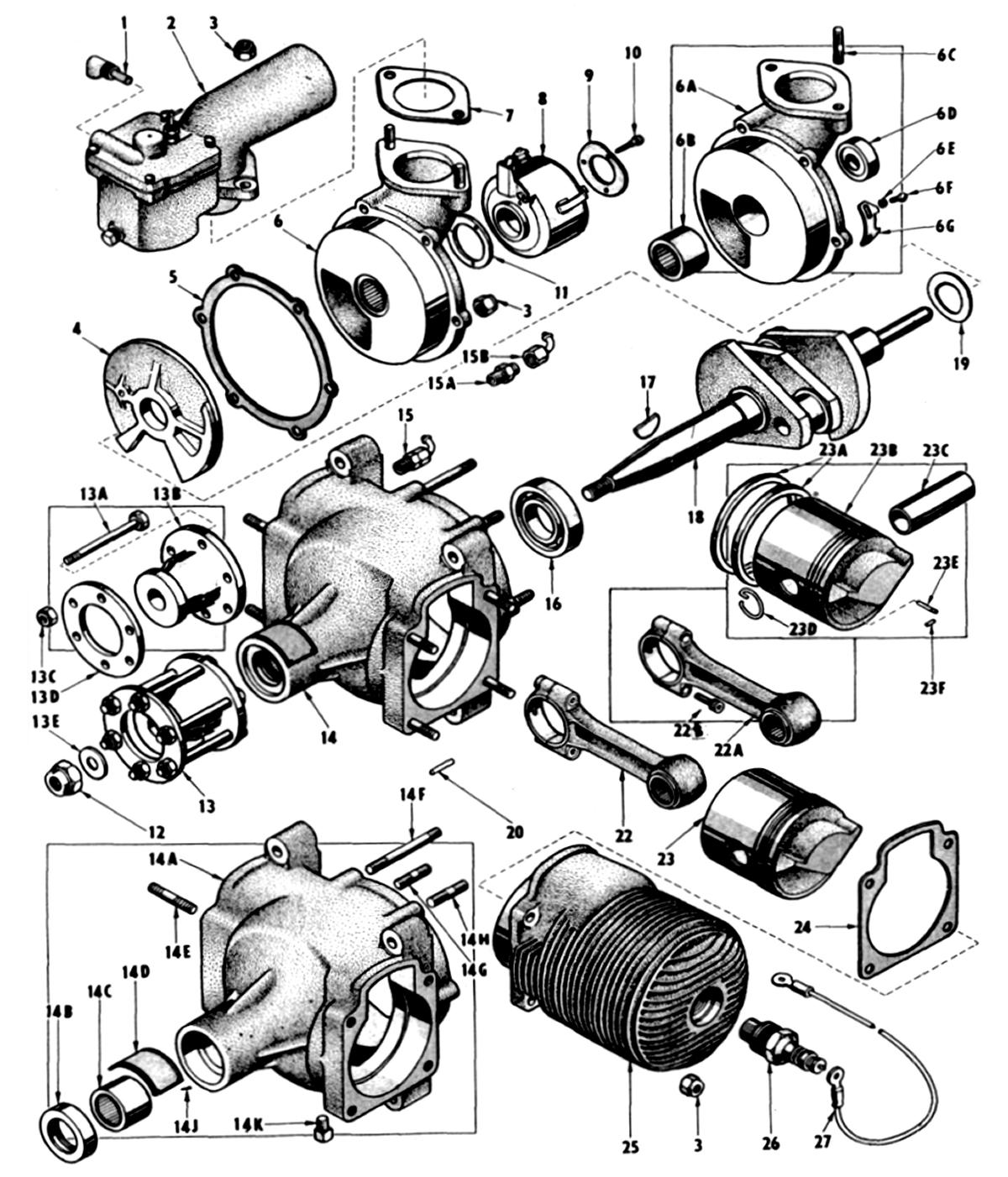 |
| Exploded diagram of the O-45-1 from the OQ-14 manual showing the roller bearings supporting the crankshaft as well as both ends of the connecting rods. A ball thrust bearing in front of the fore crank cheek takes the propeller thrust load. |
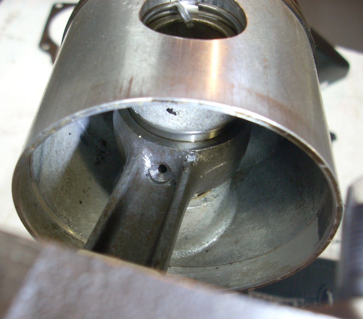
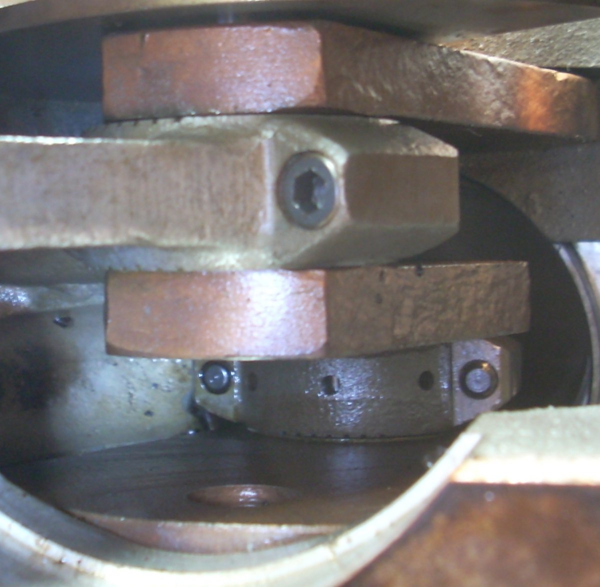
The connecting rods are steel and utilize a cartridge-type Torrington roller bearing in the little end. A chamfered hole in the little end allowed oil to access the bearing. The big end bearing for the early Righter O-45-1 engines (R1-10001 to R1-12358) was a 12-element roller bearing with two piece bearing retainer. The rest of the Righter O-45-1 engines, and all Menasco and Kiekhaefer O-45-1 engines used a 31-element cageless roller bearing in the big end. The rollers were all precision matched and not interchangeable except as complete sets. Likewise, the rod caps were precision machined and stamped as an exclusive match to the connecting rod. Rod caps are secured by cap screws and fiber lock nuts on the Righter engines, or hex head screws down into the threaded bearing cap in the Kiekhaefer and Menasco engines. Note the reliefs in the center of the bearing area in the big end of the connecting rod such that the roller bearings only roll on the outer webs. There are "saw cuts" in the side of the rod big end and either an oblong slot (Righter O-45-1) or three approximately 1/8" diameter holes in the rod cap (Kiekhaefer O-45-1) to help channel oil to and from the roller bearings.
 |
 |
 |
 |
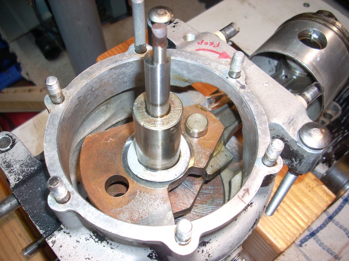
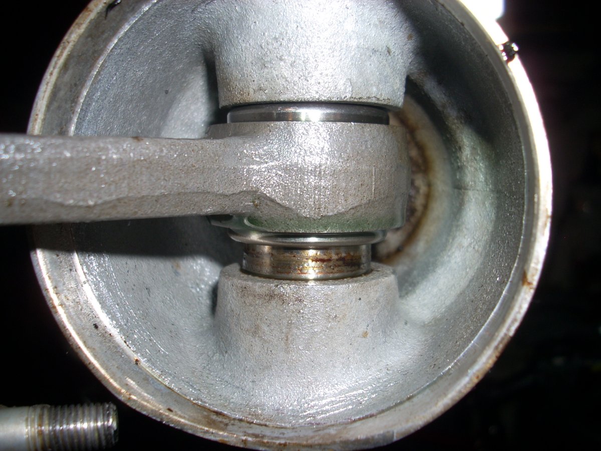
| Little end of the O-45-1 connecting rod showing the tapered oil hole accessing the roller bearings. | Pistons, connecting rods, and cageless big end roller bearings for the Righter O-45-1 engine. Note the webbed structure of the big end of the connecting rod and the slotted rod cap. | Rods in place on the Kiekhaefer O-45-1. Note the three round holes in the rod cap visible towards the bottom center of the photograph. | "Saw cut" channels on the vertical face of the big end of the installed connecting rod. Connecting rod exits crankcase to the right. Round knob at left is the drive pin for the rotary valve. |
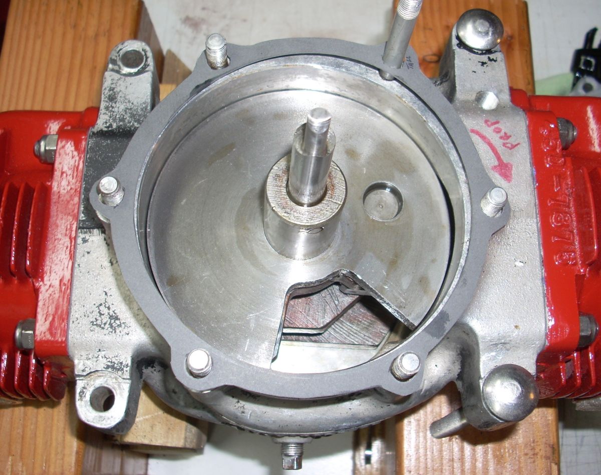
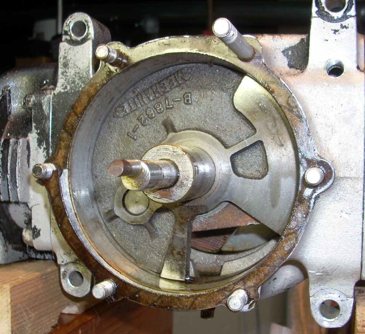
The cast iron "Meehanite" rotary valve is 4.75" in diameter, used a central spring washer to maintain pressure on the rear case face, and was driven by a steel pin on the crankshaft cheek. The cheek was relieved to allow unobstructed flow though the cut out of the rotary valve. The cut-out wedge on the rotary valve is 61° of arc, 2.44 in² of area, producing an intake duration of 149° of crankshaft rotation. Transfer duration is 141° and exhaust duration 160° of crankshaft rotation.
 |
 |
 |
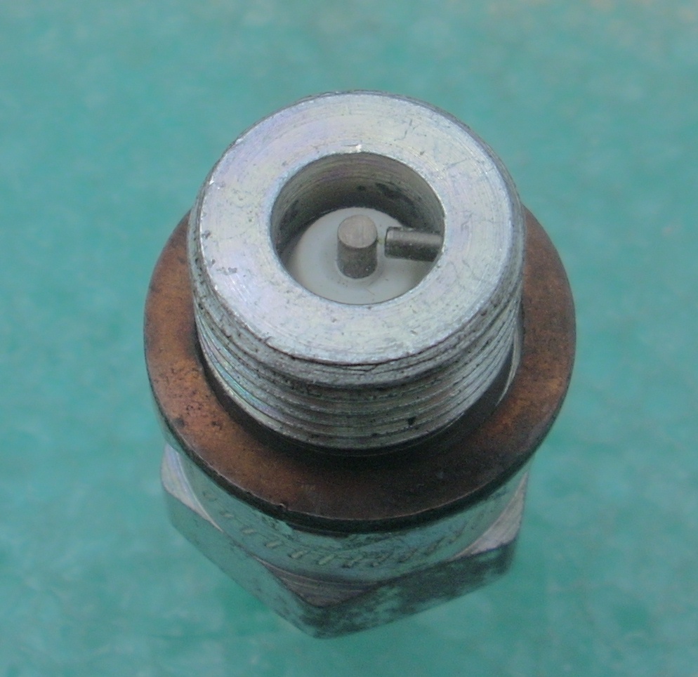
| O-45-1 rotary valve induction face in position on the crankshaft. | When this Kiekhaefer O-45-1 was purchased, the rotary valve was found installed backwards, but conveniently showing the back side of the rotary valve. The raised, machined surfaces abut the crankpin cheeks. | Rotary induction valve has been removed to show the drive pin, valve cut out on the crank cheek, and the spring washer in place on the crankshaft tail. |
The pistons look very much like those used in the O-15-3 except they are considerably larger. The underside of the piston dome is ribbed like those in the O-15-3, however the dual 0.092" thick cast iron piston rings are relieved at their ends and secured in place by a pin in the groove to prevent rotation.
The Champion R-1 (or equivalent) was the specified spark plug for the O-45-1. This is a side-electrode type plug used in racing and is designed to reduce lead or oil fouling.
 |
 |
 |
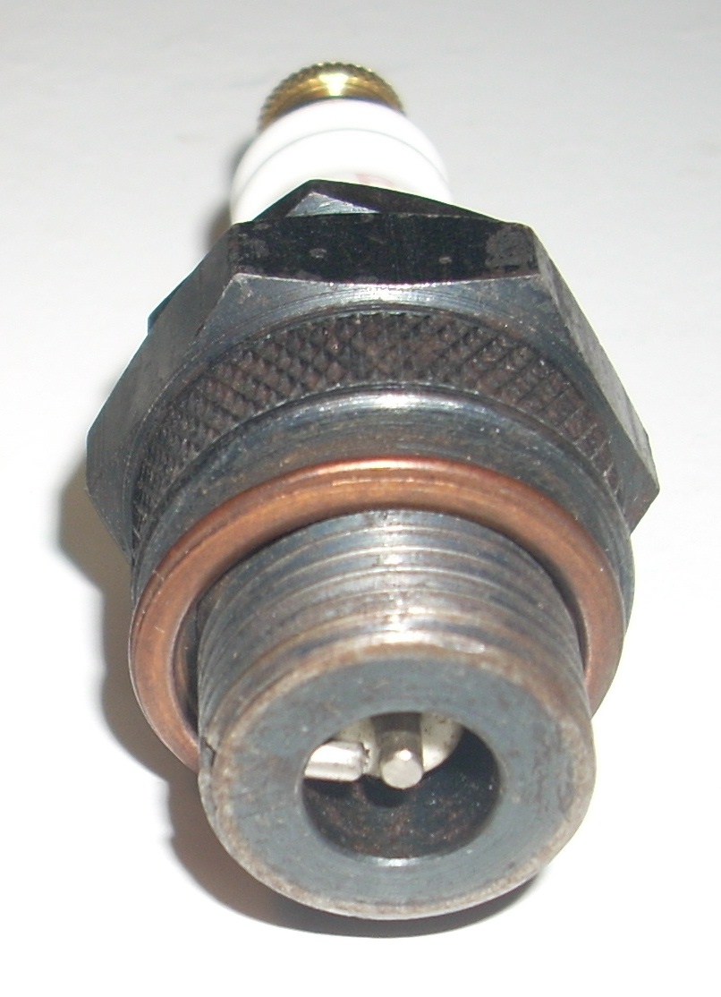 |
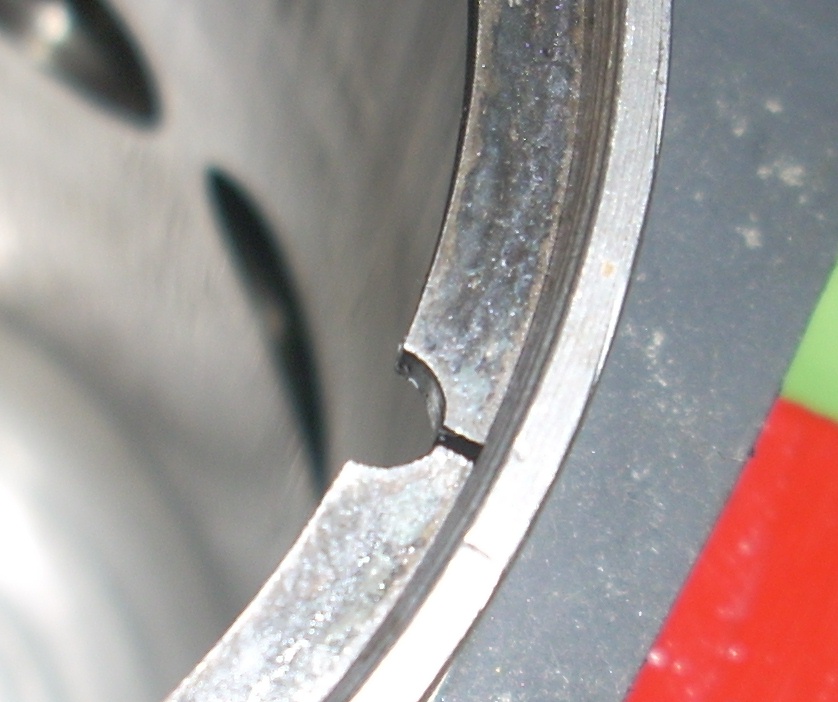
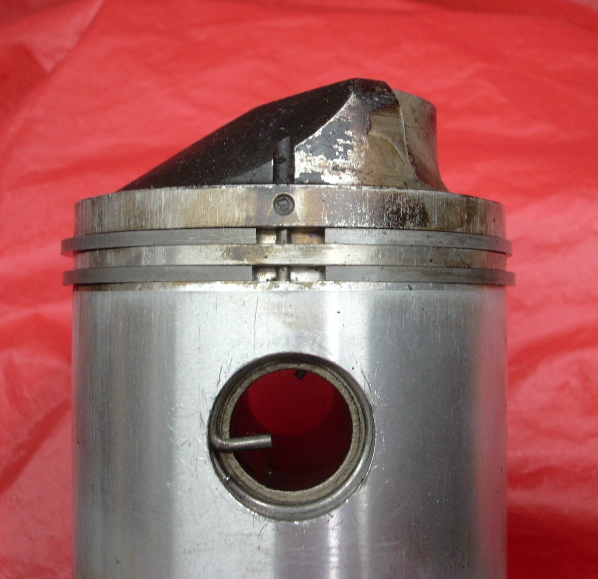
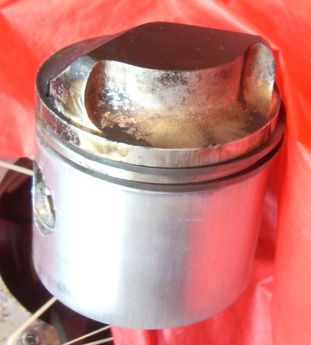
| Notched O-45-1 piston ring shown in the cylinder bore. | Notched piston rings are located in the piston groove by a pin driven into the grooves from the top of the piston. | O-45-1 piston showing the contouring of the intake side of the crown, directing the incoming charge to the top of the cylinder to force the exhaust gasses out of the cylinder. | Champion R-1 18 mm spark plug showing the side electrode design. |
The O-45-1 cylinders consist of an aluminum muff and cast iron liner with four round transfer and four round exhaust ports. The intake transfer trunk is 1.92" to 1.97" wide by 0.82" long at the cylinder/crankcase interface; it has a rough sand-cast finish and bulging contours to the walls. Within that description, there are several variations to the design depending on who manufactured the engine.
The Righter O-45-1 cylinder part number 45D7875 has an extended exhaust stack that projects outward approximately 1" from the cylinder fins. It has four round 0.694" diameter ports on the arc, or 1.537 in² total exhaust port area per cylinder. There is no aluminum backing up the port bridges. The Righter has three stub fins underneath the exhaust port, four stub fins +/- 90° to the exhaust stack, 16 barrel fins, and 17 head fins. The barrel fins are 5.08" in diameter and taper in thickness from 0.185" thick at the root to 0.07" at the periphery. The root fin gap is 0.12" and tip gap is 0.17".
The Kiekhaefer O-45-1 cylinder 45D7875 / C7875A weighs 83.2 ounces (2,359 grams) and has a short exhaust stack that does not extend beyond the barrel fins. The two central exhaust ports are 0.704" diameter on the arc, and the two outer exhaust ports are 0.543" diameter. Total exhaust ports area is 1.244 in² per cylinder. The bridges of the cylinder line are fully backed by 0.25" to 0.5" of aluminum. The Kiekhaefer has four stub fins underneath the exhaust port and 90° left and right of the exhaust stack, 16 barrel fins, and 17 head fins.
The Menasco O-45-1 cylinder 45D7875 has an exhaust stack that projects outward only 1/8" from the cylinder fins. The exhaust port dimensions and areas are the same as the Kiekhaefer and the exhaust port bridges are backed by aluminum. The Menasco has four stub fins underneath the exhaust port as well as +/- 90° to the exhaust stack, 15 barrel fins, and 19 head fins.
 |
 |
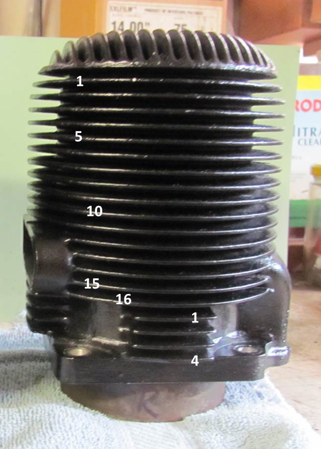 |
| Righter O-45-1 Cylinder | Righter O-45-1 cylinder showing unbacked, round exhaust ports all of equivalent diameter. | Kiekhaefer O-45-1 Cylinder |
 |
 |
| Kiekhaefer O-45-1 in non-standard red paint showing round exhaust ports of two different diameters, aluminum backing of the cylinder bridges, and the transfer ports visible through the exhaust ports. The four ports are aligned all in line at the top of the circles, not on the port centers. | Menasco O-45-1 Cylinder |
The regulated pressure tap for pressurizing the fuel tank is located on the crankcase at the starboard cylinder base. There is a 1/8" pipe plug drain on the bottom of the crankcase.
The cylinder fins, port geometry, and exhaust stacks make O-45-1 cylinders by Righter, Menasco, and Kiekhaefer different from each other. The Righter has a port area 25% larger than the Kiekhaefer and Menasco area, but lacked aluminum backing on the liner bridges. Aluminum backing of the exhaust bridges helps to dissipate heat from this relatively small (and hot) strip of cylinder liner. I can't say whether the naked Righter bridges had tendency to warp or not, but I can say the aluminum-backed bridges of the Kiekhaefer and Mensaco cylinders would be more resistant to such a problem. The number and distribution of cylinder barrel and head fins is also differs between all three cylinder manufacturers, indicating each company developed their own cylinder design. Despite the physical differences between cylinders, they all carried the same part number and were interchangeable on all three O-45-1 engines.
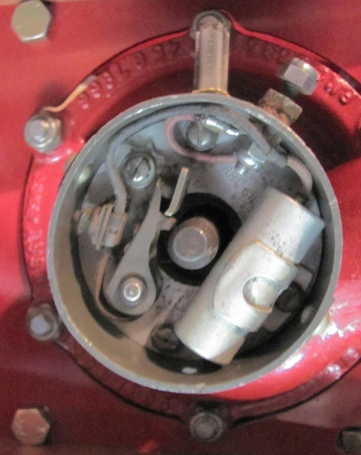
On the aft end of the rear case is the manually-operated ignition timer assembly identical in part number, design, and 30° maximum advance to that found on the O-15-3 engine.
O-45-1 engines use two types of ignition cams. Righter and Menasco engines used the "depression" type cam in previously described for the O-15-3 engines. The "pin-type" cam has the crankshaft dowel machined to leave an eccentric pin of native material that acts as the cam to open the breaker points. Interestingly, Kiekhaefer used the depression cam at least through August of 1945 (serial number KC 82019), but engine serial KC 83396 has the pin-type cam. Both cam types are cylindrical dowel-like sub-assemblies inserted and pinned into the crankshaft.
 |
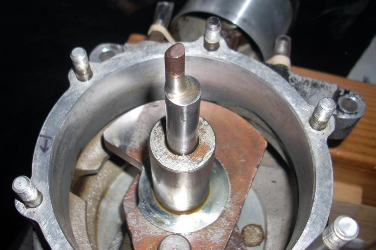 |
| Depression-Type Cam on the Righter O-45-1. Depression area is from 9 o'clock to 12 o'clock in this view. | Pin-Type Cam on the Kiekhaefer O-45-1. Also of note is the spring washer on the crankshaft tail that applies aft-directed pressure on the rotary induction valve to seal it against the rear cover. |
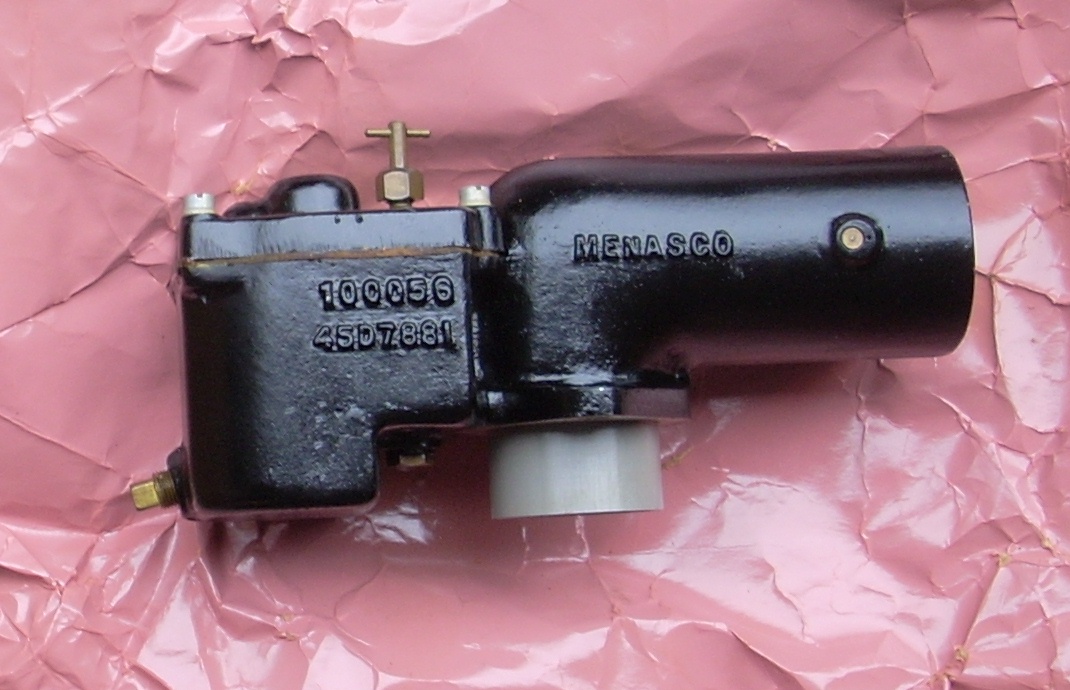
O-45-1 carburetors are 90° down-draft units made specifically for this application. There is no throttle, only a spring loaded choke, and the mixture needle is located on the top of the unit. The carburetor intake is 1.92" in diameter and faces rearward. Carburetor Assembly #45A7879 (OQ-14 manual) were manufactured at least by Righter Manufacturing Company (R.M.C.), Menasco, and by Kiekhaefer as part #C-7881 or XC-7881. Only Menasco carbs have a green zinc chromate primer underneath their black paint, and some O-45-1 carbs are devoid of manufacturer markings. The carb is designed to run on 2 to 4 psi of fuel pressure and the recommended fuel-to-oil ratio is 6 to 1.
 |
 |
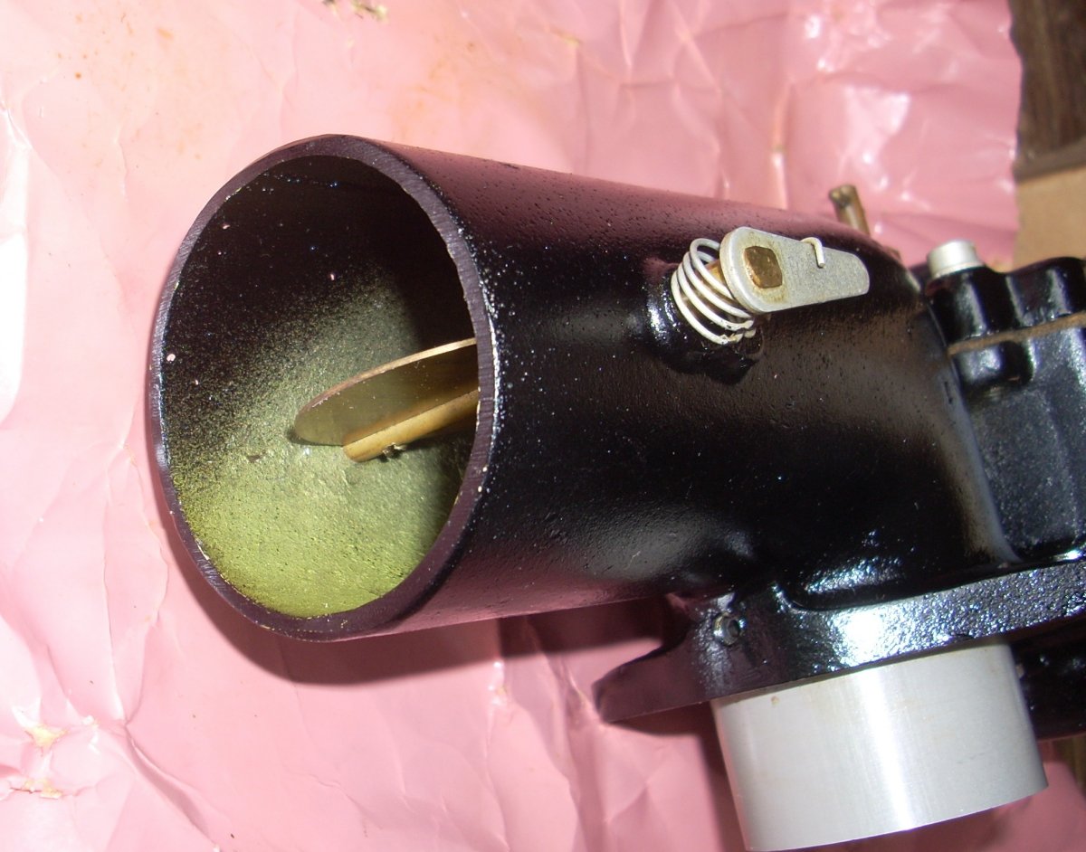 |
| Carburetor Exploded Diagram from the O-45-1 Engine Manual | Menasco O-45-1 Carburetor. This unit was new-old-stock in the original box, wrapped in the original heavy, glossy pink paper. | Menasco O-45-1 Carburetor Showing the Zinc Chromate Primer |
The O-45-1 propeller is a 32" diameter x 36" pitch, triple or quadruple laminated wood unit that sits on a six bolt hub. Many of these propellers (part number 45D7796) were made by Kroehler, but many are unmarked save for the part number and a 2" red painted tip.
 |
 |
| Kroehler O-45-1 32" x 36" Propeller Used in the Radioplane OQ-14/TDD-3 Aerial Gunnery Target. The propeller weighs 26.5 ounces. | Kroehler O-45-1 32" x 36" Propeller Showing the Aggressive Pitch Contour of One Blade |
The Kiekhaefer O-45-35
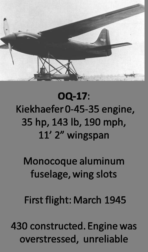
In the quest for greater speed and performance from the gunnery targets, the final opposed twin engine of the production Radioplane drones was the Kiekhaefer O-45-35. While this engine and the OQ-17 / KDR-1 airframe first flew in March of 1945, it did no go into production until 1946. The OQ-17 sported a sculpted monocoque fuselage of aluminum, cantilevered wings with slots, and a fully-cowled engine with spinner giving it a 190 mph top speed and 5,100 fpm of climb. Only 430 OQ-17s were made. Their downfall was the brittle, cantankerous nature of the 35 pound, 35 horsepower O-45-35 engine.
 |
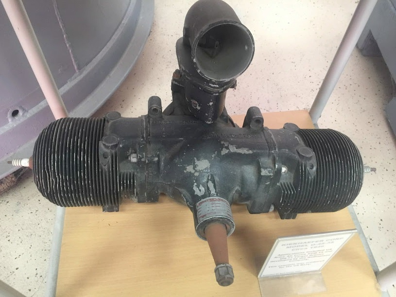 |
| Radioplane OQ-17 Aerial Gunnery Target Powered by the Kiekhaefer O-45-35 Engine | Kiekhaefer O-45-35 |
At first glance the O-45-35 doesn't look too different from the O-45-1 except for the larger, taller carburetor that faces forward instead of aft. But upon closer inspection, the cylinder fins are a different configuration, thinner, and more numerous than the O-45-1. The intake transfer trunk looks quite different as well. Once we look inside the O-45-35, it is clear this is a different beast than the O-45-1.
 |
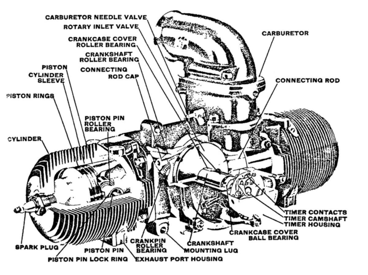 |
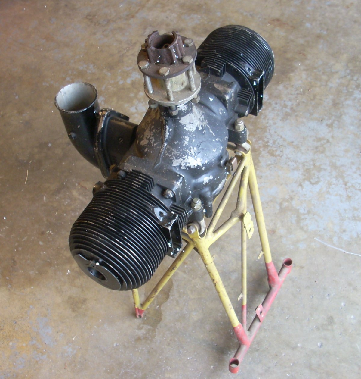
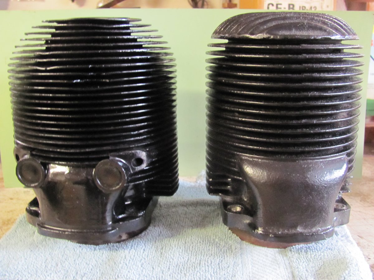 |
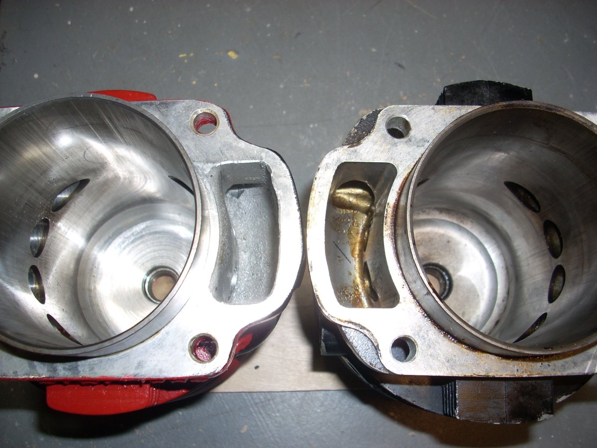
| Kiekhaefer O-45-35 on what is believed to be an engine mount for the otherwise extinct Radioplane OQ-17. Cylindrical receivers for the catapult lugs are at the ends of the red painted framework. | Kiekhaefer O-45-35 Cut Away from the Engine Manual | Kiekhaefer O-45-35 (35 hp) Cylinder on the Left; Kiekhaefer O-45-1 (22 hp) Cylinder on the Right. Notice the thin, more numerous parallel cylinder finning as well as the wider transfer trunking with dual Welch plugs of the O-45-35 compared to the O-45-1. |
The O-45-35 has the same 3.25" bore and nominal 2.75" stroke as the O-45-1. The steel connecting rods are the same 5" length for both engines. The height and general shaping of the "deflector" style pistons are the same, but there are three 0.085" thick piston rings on the O-45-35 versus two 0.092" rings on the O-45-1. And there is an arc-shaped cut-out on the piston skirt of the O-45-35 and no ribbing on the underside of the piston crown.
 |
 |
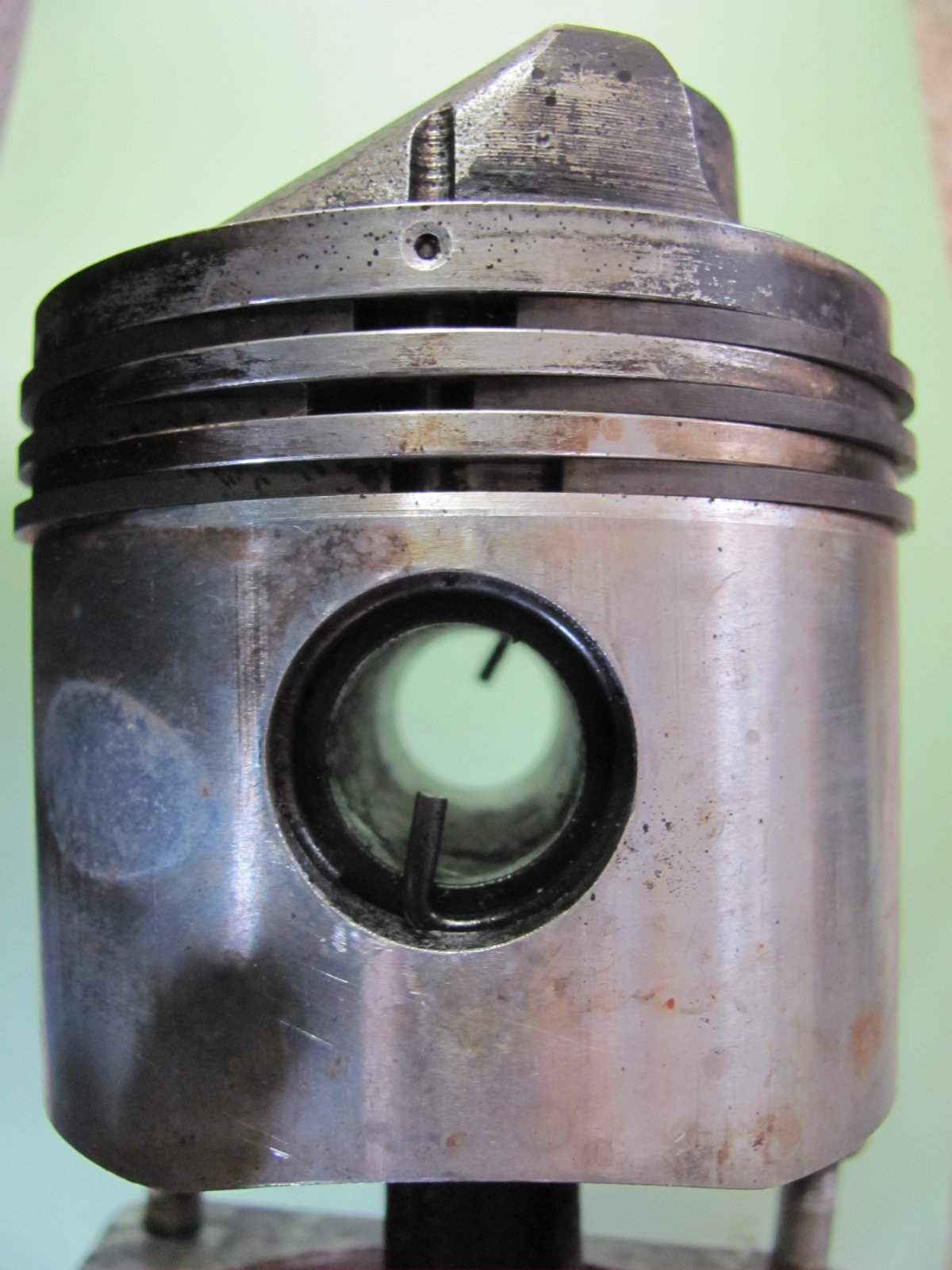
| Kiekhaefer O-45-35 Piston. Note three rings and cut out scallop on the piston skirt. | Underside of Kiekhaefer O-45-35 Piston Showing Smooth, Non-Ribbed Surface |
The rotary induction valve is 5" in diameter, 0.25" larger than the O-45-1, which necessitated the piston skirt scallops to clear the valve at BDC. The larger diameter rotary valve required a redesigned rear crankcase and crankcase cover. The induction valve has a cut-out wedge spanning 85° of arc and an area of 2.44 in². Intake duration is 180°; transfer duration is 136°, and exhaust duration 164° of crankshaft rotation.
The diameter of the intake trunk at the carburetor deck is 2.26", which is 27% larger by diameter, but 61% larger by cross sectional area compared to the O-45-1 casting. The carburetor stud centers are the same on both engines, so the O-45-1 carburetor could fit on an O-45-35 engine and vice versa.
 |
| Intake trunk at the carburetor deck for the O-45-1 (1.78" dia.; right) and O-45-35 (2.26" dia, left) engines. |
O-45-35 cylinders are die cast aluminum alloy with a cast iron liner 0.1" thick. They weigh 5 lb 3.6 ounces (2,370 grams) each. The fin gaps are very uniform and all surfaces are exceptionally smooth compared to sand casting. All the cylinder finning is axial on the cylinder bore. The barrel fins are 5.5" in diameter and taper in thickness from 0.093" thick at the root to 0.045" at the periphery. The root gap is 0.09" and tip gap is 0.15" between fins. The O-45-35 has five stub fins underneath the exhaust port as well as 90° left and right of the exhaust stack, and 26 full or partial circumferential barrel fins.
There are dual 10-24 tapped holes that flank the spark plug fore and aft that may have been used for securing the sheet metal engine cowling, and there is a single ¼-20 tapped hole about 2" below the exhaust stack that may have served the same purpose. In addition, there are ¼-20 tapped holes that flank the transfer trunk.
 |
 |
 |
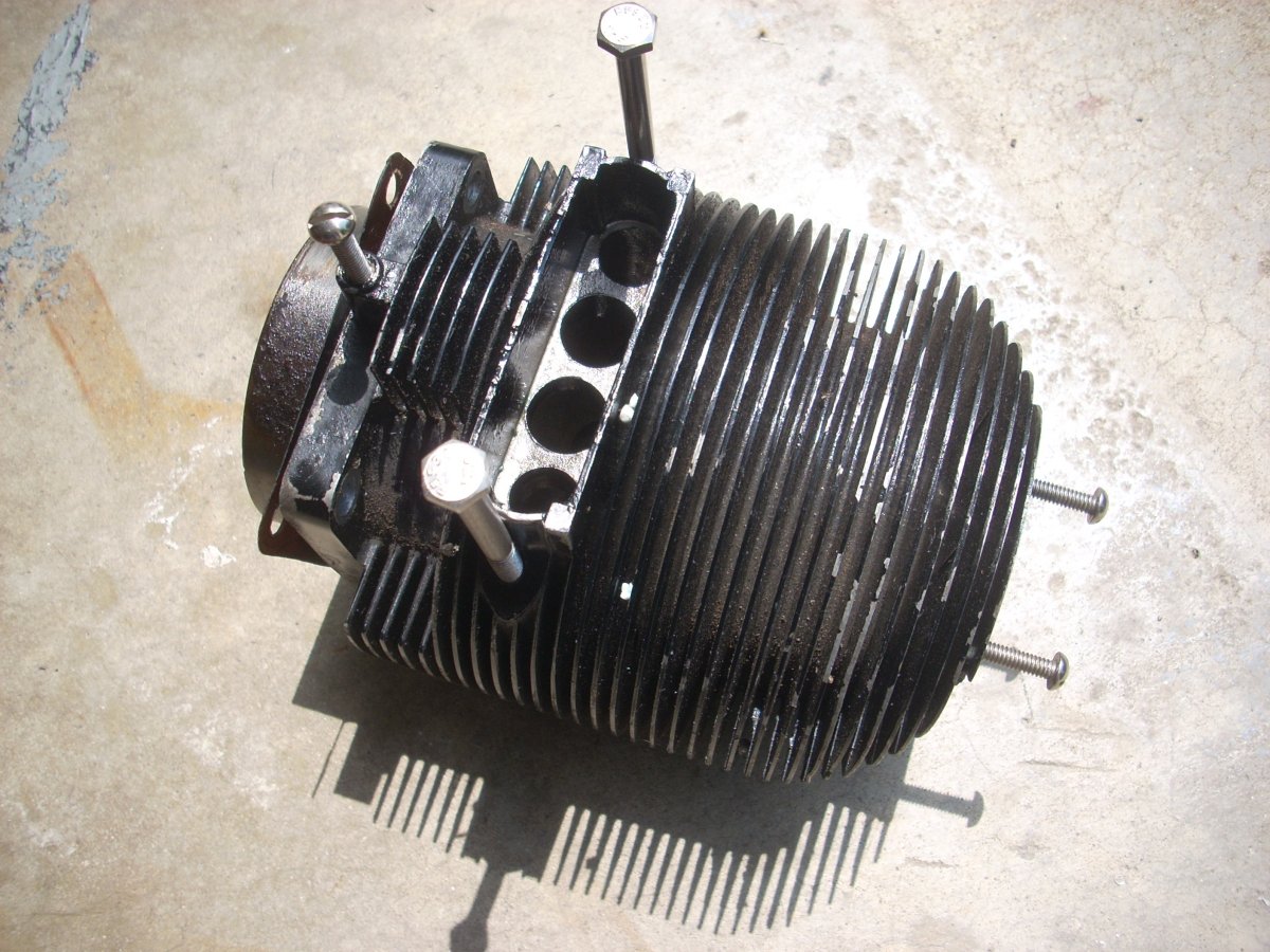
| Kiekhaefer O-45-35 cylinder top showing axial finning all the way to then end of the cylinder and two tapped holes flanking the central spark plug hole. | Kiekhaefer O-45-35 cylinder with non-standard bolts inserted to show the location of the tapped holes flanking the spark plug, exhaust stack, and below the exhaust stack, perhaps used to secure cylinder baffling and/or the sheet metal cowling. Note the depth and uniformity of the fins by the shadow. | Kiekhaefer O-45-35 cylinder with non-standard bolts inserted to show the location of the tapped holes flanking the transfer trunk, perhaps used to secure cylinder baffling and/or the sheet metal cowling. |
The two, round, central exhaust and transfer ports of the O-45-35 measure 0.7" in diameter on the arc while the two flanking ports are 0.58" in diameter on the arc. The stout, rectangular exhaust stack extends 0.35" from the cylinder fins and there are opposing ¼-20 tapped receptacles in the cylinder muff that may have been used to secure an exhaust manifold and/or cylinder baffling.
The transfer trunk casting on the cylinder has been widened on the O-45-35 and the two outside transfer ports are drilled from the exterior to provide a larger transfer plenum than the O-45-1. Welch pugs close the holes in the exterior of the casting and are exclusive to the O-45-35 cylinder. The transfer trunk measures 2.09 to 2.12" wide and 0.82" long at the cylinder / crankcase interface and is exceptionally smooth with parallel walls.
 |
 |
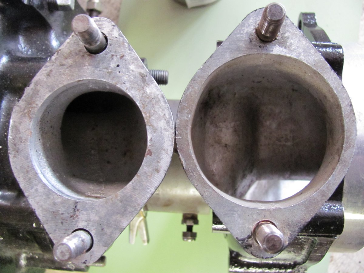
| Kiekhaefer O-45-1 transfer port on left showing rough surface, non-linear passage walls, and constricted flow path to the peripheral transfer ports compared to the O-45-35 cylinder shown on the right. | Kiekhaefer O-45-35 transfer port showing the smooth, uniform walls of the die cast cylinder and the widened passage leading to the peripheral transfer port. This was drilled from the exterior with the access hole sealed with a Welch plug, which is a distinguishing feature the O-45-35 cylinder. |
The O-45-35 cylinder head has a stepped radius between the vertical cylinder wall and the horizontal flat top of the cylinder head. The cylinder liner is inserted flush with the cylinder bore (no gap, no lip at the top of the liner). These features will be discussed in the O-45-1 versus O-45-35 section. The static compression ratio of the O-45-35 is 8.6 to 1 and the dynamic compression ratio is 6.2 to 1.
 |
 |
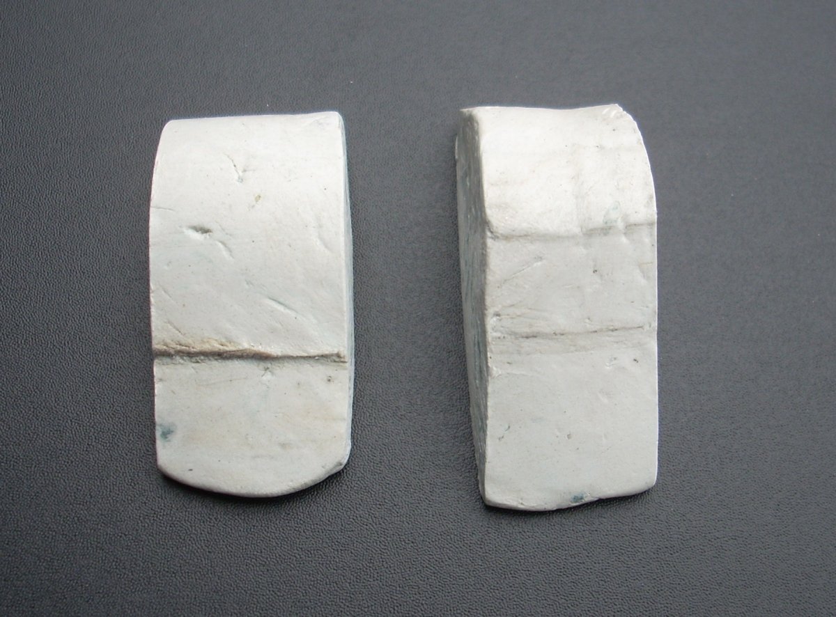 |
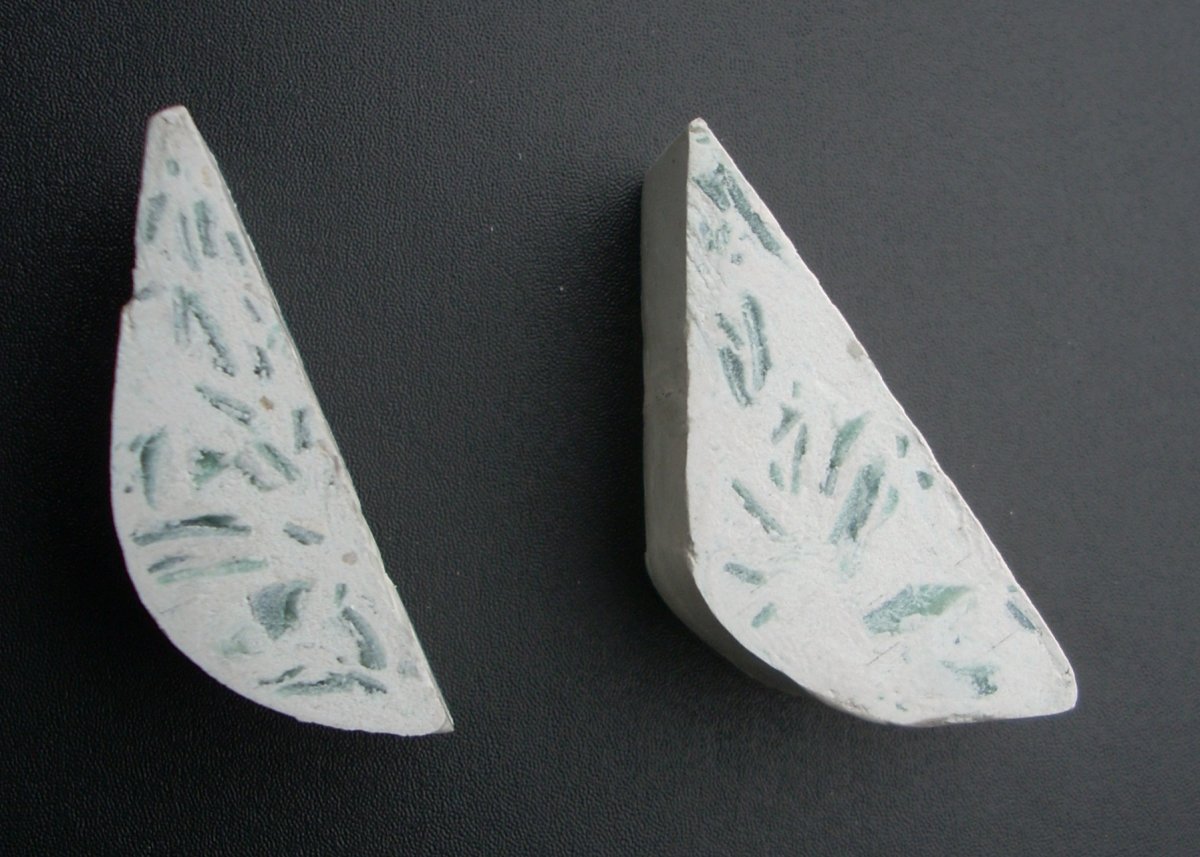
| Kiekhaefer O-45-1 cylinder on left, O-45-35 cylinder on right, showing the difference in visual appearance of the cylinder heads. | Epoxy putty was used to get contours of the junction of the cylinder wall to the cylinder head for the Kiekhaefer O-45-1 (left) and O-45-35 (right) engines. Flat top of cylinder is the horizontal bottom of the castings; cylinder wall is the vertical side. | Epoxy putty of the cylinder liner to the wall of the cylinder for the Kiekhaefer O-45-1 (left) and O-45-35 (right) engines, The O-45-35 liner is flush with the cylinder muff while the O-45-1, showing the step in the epoxy putty where the cylinder liner ends, is not. |
The O-45-35 crankshaft is similar in configuration to the O-45-1 crankshaft and both are within 1/4" of length of each other. The crank front end is supported by a Torrington roller bearing to take axial loads and a ball bearing to take the thrust loads. The O-45-35 crank tail is supported by no less than two sets of Torrington roller bearings followed by a New Departure ball bearing whereas the O-45-1 has only one Torrington roller bearing in the tail. The steel dowel inserted in the tail of the crank is machined to form the eccentric pin-type cam.
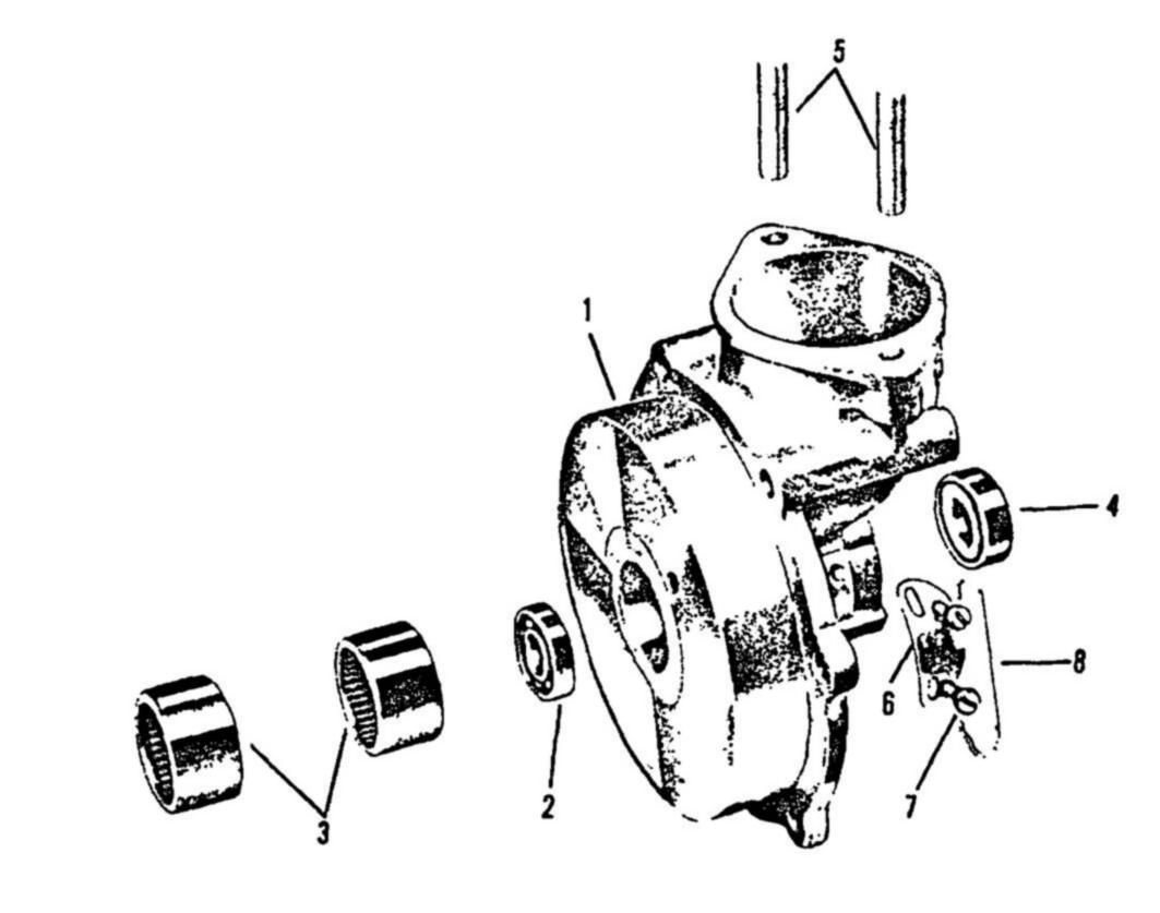 |
| Exploded diagram of the O-45-35 engine rear case: 1) rear case, 2) dual roller bearings, 3) ball bearing, 4) real oil seal, 5) carburetor studs, 6) timer rack, 7) screws, 8) safety wire. |
The O-45-35 manually-advanced timer is similar to that found on the O-45-1 engine, but has a different part / assembly number, a phenolic arm on the breaker assembly, and is limited to 29° of spark advance. The O-45-35 engine manual describes the use of a dedicated tool that is threaded into the spark plug hole to mechanically set the 29° of spark advance on the timer. Side-electrode Champion RJ-11 plugs are specified for the O-45-35.
 |
 |
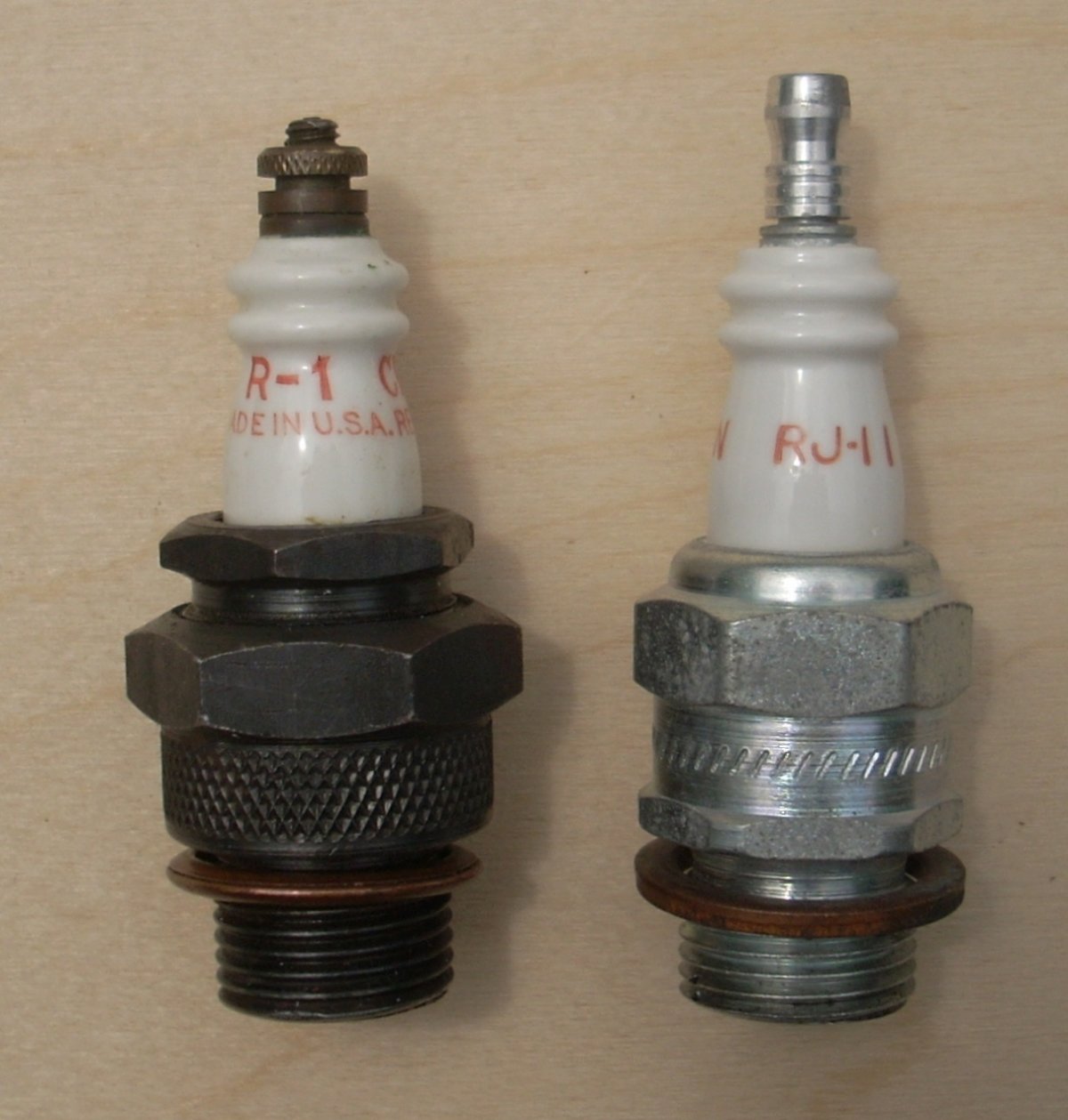 |
| Points pivot arms for O-45-35 on left and O-45-1 on the right showing the difference in design and materials between the two timers. | Champion RJ-11 Side Electrode Spark Plugs | Champion R-1 Plug for O-45-1 on Left; Champion RJ-11 Plug for O-45-35 on Right |
There is subtle shaping and ribs inside the crankcase of the O-45-35 that is not found in the O-45-1, presumably to add strength and/or improve airflow through the aluminum crankcase.
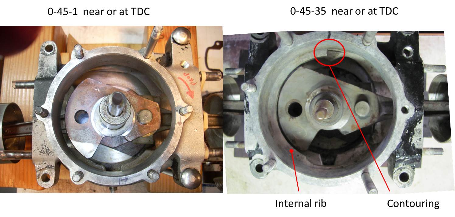 |
| Rear covers and induction valves removed from the Kiekhaefer O-45-1 crankcase on left, O-45-35 crankcase on right, showing the larger diameter rear case, ribs, and contouring in the O-45-35 not found in the O-45-1. |
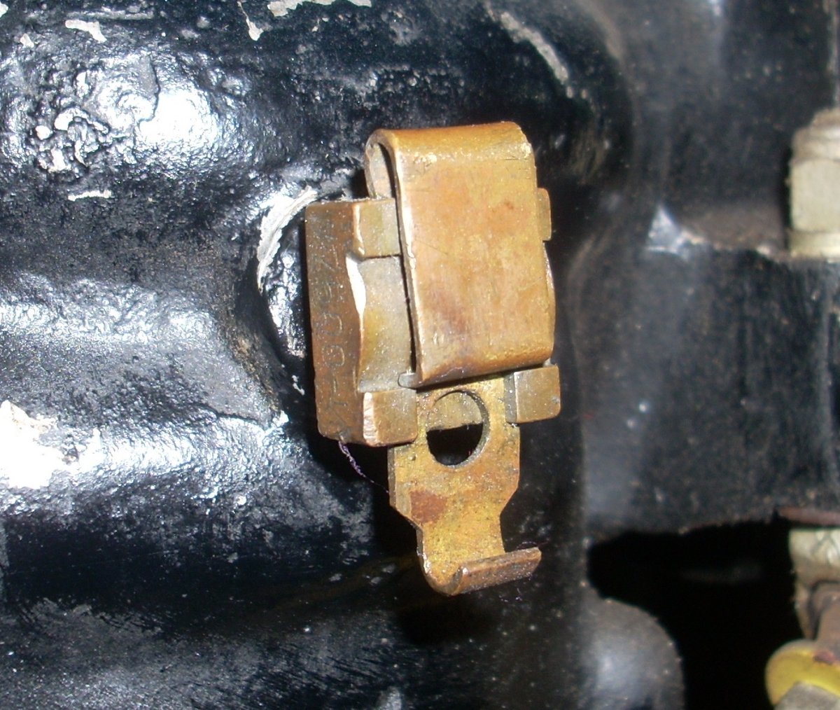
The crankcase drain plug is unique and looks similar to a money clip whereby a slide under tension can be moved fore or aft to allow quick draining of excess fuel from a flooded crankcase. The hole is surrounded by a partially-recessed rubber O-ring to seal the crankcase.
 |
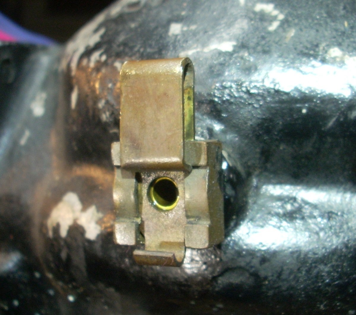 |
| O-45-35 Crankcase Drain Closed | O-45-35 Crankcase Drain Open. Not visible is the rubber O-ring that seals the orifice. |
The carburetor is designed to accept fuel pressure of 4 to 5 psi, has neither throttle nor choke, and components are sized to provide greater fuel flow that the O-45-1 carburetor. The diameter of the flared entrance is 2.75" with a main bore of 2.48". The recommended fuel mixture is 6 parts of 91 octane gasoline to one part SAE 30 oil.
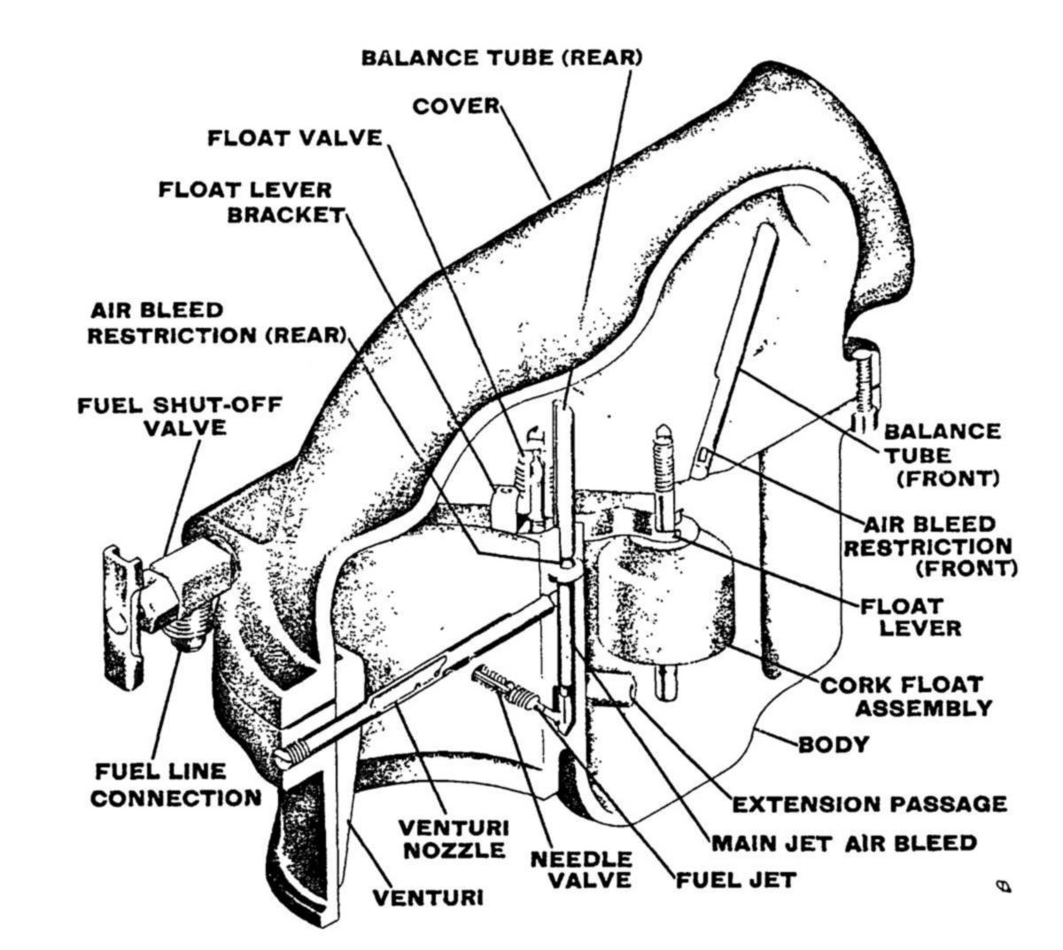 |
| Cutaway diagram of the O-45-35 carburetor that has no throttle, no choke, no idle circuit, and a single mixture needle valve. |
The propeller hub used on the O-45-35 has the same part numbers as that used on the O-45-1 engine; however the OQ-17 had a spinner with an unknown method of attachment. Curiously, there are four surviving O-45-35 propeller hubs that have a spur gear welded to the standard crush plate of the propeller, presumably for use in starting. Cinematic evidence shows the Wee-Bee (discussed below) also had this modified propeller flange, despite being started with a sling. How starting was accomplished in the military, with or without the spinner, remains unknown.
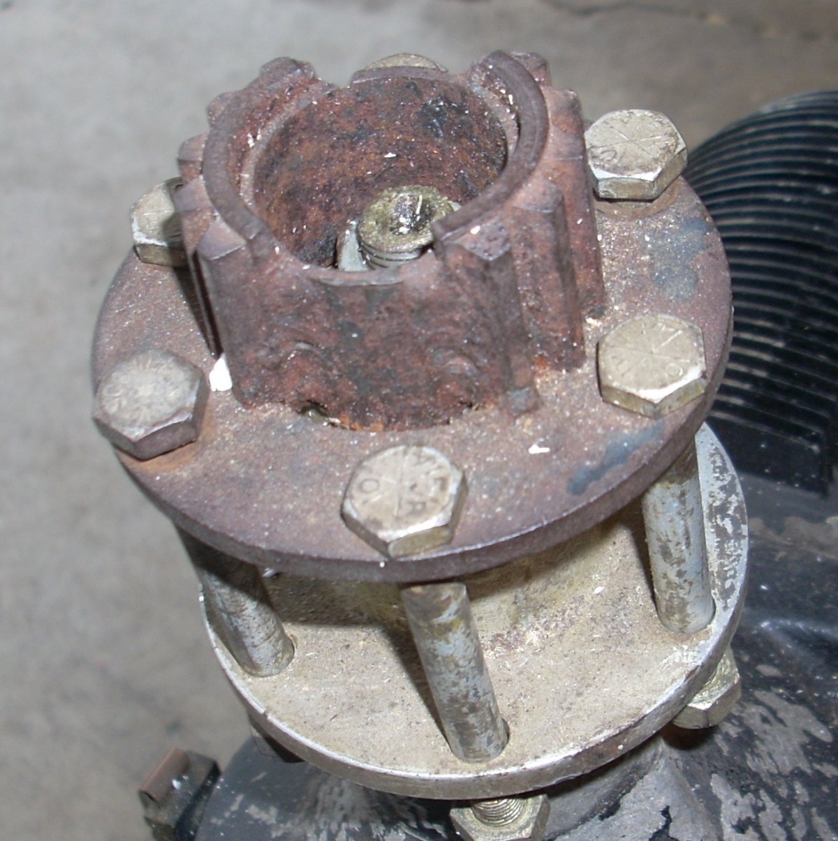 |
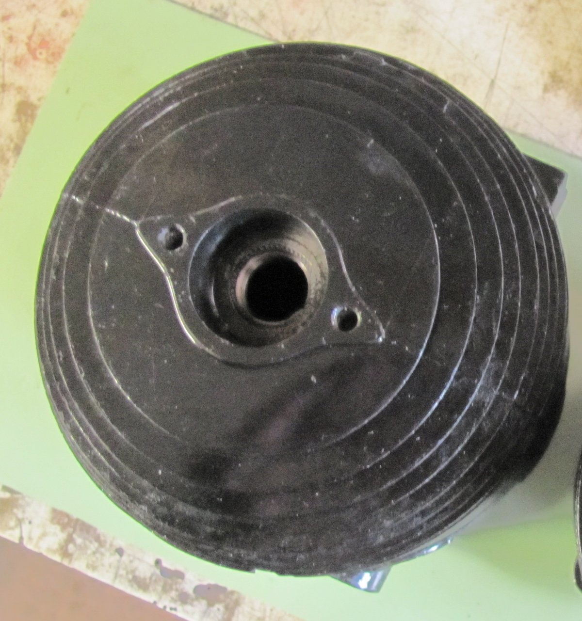
| Modified propeller flange (crush plate) of the O-45-35 engine with an interrupted spur gear welded concentric to the crankshaft. |
- On to Part 6. Performance and Efficiency Comparison between O-45-1 and O-45-35 Engines -
Send mail to
![]() with questions or comments about this web site.
with questions or comments about this web site.
![]()