Pioneer Sleeve Valve Engine 1
Pioneer Sleeve Valve Aero-Engine
by Jerry Wells
Published 3 Oct 2006
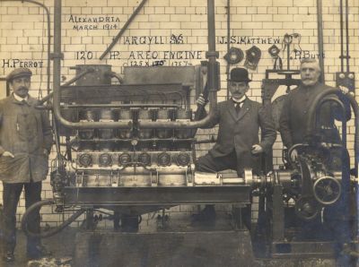
The 12.8 litre Argyll sleeve valve aero-engine on the Company's test stand in early March, 1914 prior to being sent to London for the Olympia Show held from mid-to-late March. Alongside the engine are designer Henri de Perrot, managing director Col. John Smart Matthew and father of the single sleeve valve engine, Peter Burt, then aged 58. The graphics on the photo were obviously done in a hurry as evidenced by the reversed "n" in Alexandria, the incomplete "E" in Perrot, the misspelt "AERO", confusion over the stroke of the engine and the lower case spelling of the "Burt" name! (Glasgow University Archive Services)
|
Over the course of piston aero-engine history, the sleeve valve type has been quite well represented. In Britain, thousands of Bristol and Napier engines with this unique kind of mechanism were manufactured. In America and Germany, interest in the apparatus was such that a lot of prototype construction and testing was carried out.
Thus, by the end of the piston engine era, sufficient experience of the sleeve and poppet valved kind had been obtained to allow meaningful comparative conclusions to be drawn between the two types. Of course there were pluses and minuses but, in an overall sense, it was clear that the sleeve valve never provided a quantum leap in engine performance over the poppet valve type. If it had, it would have replaced the poppet valve quickly and completely.
|
The Origins of the Sleeve Valve
The sleeve valve story starts in the early 1900s when Chicago based engineer Charles Yale Knight (1868 - 1940) began experimenting with cylindrical valves in an effort to circumvent the problems of weak valve springs and burnt poppet valves that were plaguing the automobile engines of the time.
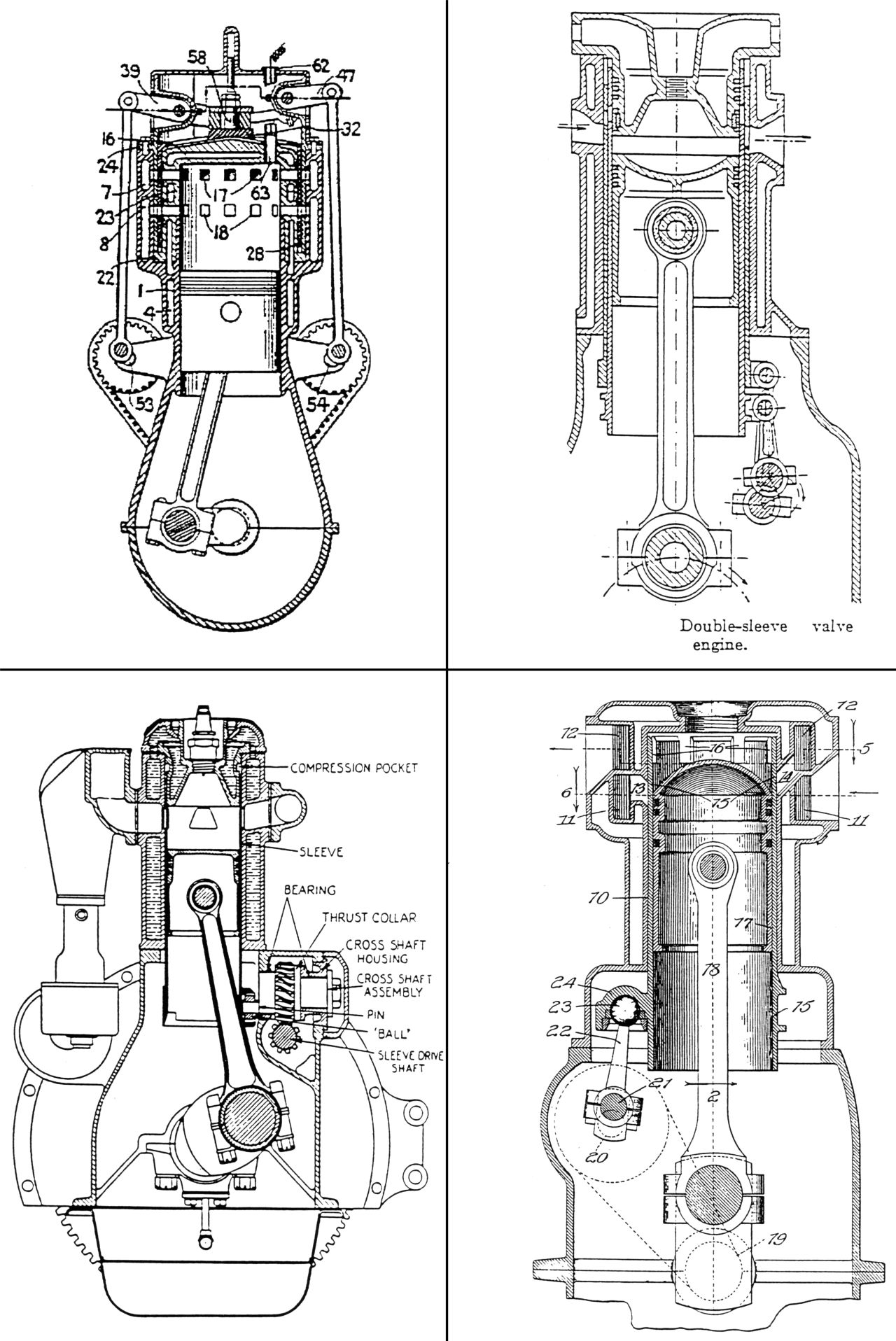
With the double-sleeve valve system (see fig. 1, top right) Knight had a viable alternative to offer the auto fraternity and the system was widely adopted in both the U.S. and Europe.
Whether Burt and McCollum were inspired by the Knight invention is hard to say but just as the "Silent Knights" were becoming numerous on the roads, the single-sleeve breakthrough was made.
 |
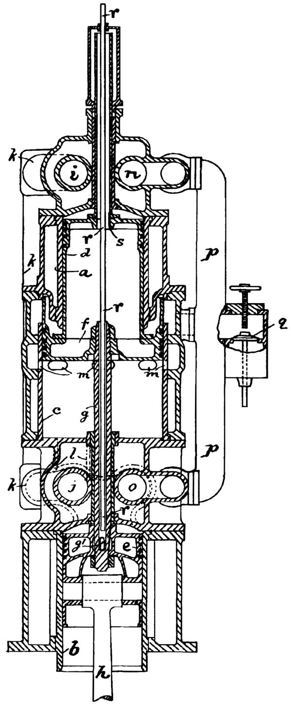
Scottish engineer Peter Burt was born in Glasgow in 1856 and almost from the cradle began to invent things and file patents for them! All his patents, which date from the 1880s up to the Second World War, give his address as “Hollybank”, Silverwells Crescent, Bothwell, his home for all of his life. One of his early engines is shown in figure 2. How it was supposed to work is difficult to fathom! One hopes his washing machines were mechanically simpler.
The Argyll Motor Co. began in 1896 but its bid for a place in the U.K. car market did not take place until 1906 when a palatial factory was built at Alexandria, a town located to the north west of Glasgow. The company, then called Argyll Motors Ltd., struggled. In 1908 it was partially liquidated and then refloated as Argylls Ltd.
Two years later, Peter Burt approached the manager, John Matthew, with a design for a car engine featuring sleeve valves which would thus eliminate the often noisy conventional valve actuating gear. Burt’s design was accepted and incorporated into an Argyll car, which from all accounts was a fine vehicle. Production began in 1911.
Nonetheless, the Company could not achieve commercial success. There were costly legal battles over Burt’s patents and in 1914 the shareholders lost confidence. No new backing was forthcoming and the Company again went into liquidation just at the time the 1914 Naval and Military Competition for aero-engines was held.
It is highly likely that the decision by Argylls to enter the 1914 N & M competition was prompted by the financial difficulties the Company was having. A government military contract to produce aero-engines would have been very lucrative especially considering the prospect of war with Germany and therefore, large production numbers. After all, that other famous Scottish company, D. Napier & Son, changed from vehicle manufacture to aero-engine production during WWI and the shift in emphasis resulted in handsome profits.
|
| Fig. 1. Four Sleeve-Valve Engines. Top Left - McCollum, 1909. Top Right - Knight, 1908. Lower Left - Continental, 1926. Lower Right - Sargent, 1914. |
 |
| Fig. 2. One of the Weird and Wonderful Engine Designs of Peter Burt. Three pistons, d, e and f, are connected in tandem via piston rod, g, and to the crankshaft via connecting rod h. The lower portion of a large low pressure cylinder, c, receives exhaust from two alternately-firing tandem high pressure cylinders, a and b, via pipe, k, were further expansion and power extraction occurs before eventual release to the atmosphere through ports m. The upper portion of the low pressure cylinder helps pump the intake charge that enters via check valve, q. Air or water, entering through pipe, r, and exiting through annular space, s, helps cool the hollow pistons. (GB190023,696) |
 |
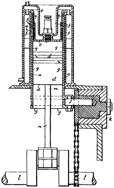
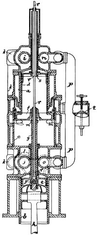
Fig. 3. Prototype Burt Sleeve-Valve Engine |
The sleeve valve as envisaged by Burt is clearly depicted in Letters Patent document No GB 190,918,140 dated 6 August, 1909. Burt describes the mechanism as, "This invention which relates to internal combustion engines and particularly to that class of such engines as are of the high-speed type, has for its object, by means of the special construction of the engine cylinder and of the construction and arrangement of the working parts within said cylinder, the provision of a simple and efficient engine which is practically noiseless in its action." However, at the end of the patent, he says, "We are aware that in connection with internal combustion engines, it has already been proposed to employ a cylindrical valve and give the same both oscillatory and reciprocating movements in order to control the inlet and exhaust and we, therefore, do not broadly claim such an arrangement." This may be some recognition of the work of James McCollum whose name does not appear on the patent document at all.
To move the sleeve valve in his prototype engines, Burt attached two lugs to the basal part of the sleeve. A pin was placed between the lugs and secured to them by a bolt. The pin, at its other end, made a sliding fit into a rotatable drum; the pin hole being drilled eccentrically so that when rotated by the chain drive from the crankshaft the sleeve moved both vertically and in a rotational sense (see fig. 3). It was some years before the familiar crank-and-ball joint drive was adopted.
This arrangement was suitable for single-cylinder prototypes but for multi-cylinder engines the drive had to be from the side so a shaft running parallel to the cylinder bank and driven at half speed from the front or rear of the crankshaft was used. Worm gears on the shaft meshed with those on the outside of the drums. This type of drive for the sleeves was used on the production Argyll cars and on the prototype 120 hp Argyll aero-engine. The lower left panel of figure 1 is a transverse section of the proposed Continental 6. The sleeve drive here is similar to that used in the Argyll autos but is slightly more advanced in that the connection at the sleeve uses a ball joint.
James Harry Keighly McCollum was a resident of Toronto, Canada and he describes himself as a "mechanical engineer". His idea of how a sleeve valve engine should work is detailed in Patent No GB 190914,629 which was filed on the 22 June, 1909 just two months before that of Peter Burt. McCollum describes his invention as follows, "The valve gear employed is of the type which has both lateral and reciprocatory movements in order to control the inlet and exhaust and according to the present invention, such valve is arranged substantially coaxial with the piston. A further feature of the invention is that such valve is provided with two sets of ports, one set adapted to register with a set of inlet ports in the cylinder and the other set adapted to register with a separate set of exhaust ports in the cylinder."
Although, in principle, the McCollum valve operates in the same way as the Burt sleeve, there are differences. In the Peter Burt sleeve valve engine, the sleeve is an open-ended cylinder which fits between the piston and the cylinder wall. Thus it is subject to considerable pressure and temperature during the operation of the engine. The sleeve is controlled from the inside of the crankcase and from the base of the cylinders.
In the case of the McCollum variation, the sleeve is a cylinder closed at the top and fitted completely exterior to the cylinder, i.e., it fits over the cylinder outside of the inlet and exhaust ports (and the water jacket as well) so it only gets a blast from the combustion process at the spot where the sleeve valve shuts off the exhaust ports.
To operate the valve, the McCollum cylinder is fitted with normal pushrods and rockers, except that the "inlet" pushrod and rocker causes the sleeve to go up and down while the "exhaust" apparatus causes the sleeve to rotate. Thus, all control of the sleeve is from the top of the cylinder. This arrangement would, of course, produce all the noise and rattling that normally emanates from such a system.
What a study of the respective patents of McCollum and Burt shows is that all the automobile and aero-engine applications of the so called Burt-McCollum system are much more "Burt" than they are McCollum!
Any records of the McCollum engines being built and tested seem to be lost in the annals of time. However, the same does not hold true for the Argyll/Burt 6 cylinder aero-motor. At least two of these engines were built and although they never got airborne or tested in combat, they did get an opportunity to display their wares and to be compared with contemporary engines by way of the 1914 Farnborough trials.
- To Pioneer Sleeve Valve Engine (2) -