
Pioneer Sleeve Valve Engine 2
Pioneer Sleeve Valve Aero-Engine
by Jerry Wells
Published 3 Oct 2006
The Great Engine Competition
In June, 1913 the British War Office per document "87/1545 N.& M.E.C.C. Form A", announced that a competition for British-built aircraft engines would be held at the Royal Aircraft Factory, Farnborough, Hampshire, starting on 1 February, 1914. Entries had to be in by 1 August, 1913 (with a refundable entry fee of £50, about US $6,000 as of 2006) and engines were to be delivered by 15 January, 1914. A prize of £5,000 (approximately US $600,000 as of 2006) was offered for the winner and orders of up to £40,000 (approximately US $4.8 M as of 2006) were promised to not just the winner but also to any manufacturer of "engines which fulfill requirements (and are satisfactory for use)"
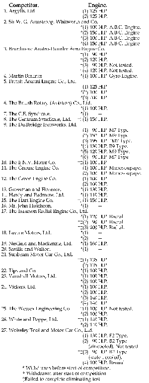
Entries poured in (see Table 1); the Germans were there courtesy of the Scottish Beardmore Company which produced Austro-Daimlers; the French were very well represented via British built Monosoupapes, Salmsons, Anzanis and Renaults and more than a dozen British manufacturers paid their deposit.
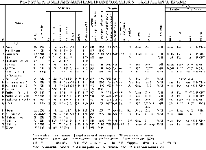
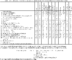
The start of the competition was delayed by three months due to the Royal Aircraft Factory being inadequately prepared for the testing, but once underway, there followed two months of noise, oil smoke and petrol fumes and at the end of it all, 11 engines had done enough to be eligible for assessment. As can be seen from Table 3, two entries, the Green and the Gnome, scored three "V.G.I." ratings and the Green with 10 "V.Gs" compared to the Gnome's 4 got the nod from the judges. The Argyll performed moderately well but three broken crankshafts would not have gone unnoticed by those adjudicating! For the Green Co., winning the competition did them no favours at all—the production of Green engines during WWI was minuscule. Still, half a million dollars in prize money would have cheered them up!
The Performance of the Argyll Engine
As might be expected for such an important and comprehensive contest, a detailed report of all testing and findings was produced. The part pertaining to the Argyll engine is reproduced in figure 4.
|
ARGYLL 120 HP. SINGLE SLEEVE VALVE ENGINE General.—This engine has six separate vertical steel cylinders with steel water jackets welded on. The cylinders are secured to an aluminium crank case by means of long bolts which support the main bearing caps. The cylinder dimensions are 125 mm. bore and 175 mm. stroke. There are no valves of the ordinary type, these being replaced by a single cast iron sleeve valve fitted between the piston and cylinder walls, which alternately covers and uncovers inlet and exhaust ports in the cylinder walls. The cylinders are provided with detachable water-cooled heads in which two plugs are fitted. Cooling.—Water cooled by means of a centrifugal pump, the water being cooled in a honeycomb radiator. Lubrication.—Two oil pumps are provided—the first pumps oil under about 25 lbs. pressure to the crankshaft bearings, sleeve actuating gear and other vital parts; the second pump sucks oil from the base chamber and returns it to the tank. The oil tank is carried at the rear of the engine and is provided with gilled tubes to cool the oil by radiation. Ignition.—The high tension two spark Bosch magneto is fitted, which supplies both plugs. A hand starting magneto is also fitted. Carburation.—Two Zenith carburettors are fitted, each supplying three cylinders. Pistons.—Are of steel and are fitted with two rings each. Crankshaft and bearings.—The crankshaft has seven journals running in seven white metal bearings, a large double ball thrust being provided at the propeller end. Hand starting gear.—This is so arranged that the engine can be turned without the pilot leaving his seat. Trials. On May 1st engine No. 1 made a trial run, but trouble was experienced with the oil circulation and with overheating. A canvas screen was then fitted to improve the radiation. On May 4th the 6 hours' test was attempted and the engine ran very smoothly and quietly at 1203 r.p.m. and developed an average H.P. of 117.9. After 2 hours 36 minutes a steel cover plate cracked, causing the oil in the valve actuating mechanism casing to run out. For this reason the engine was stopped and the test abandoned. On May 5th a second attempt at the 6 hours' test was made, but after 2 hours 11 minutes running at 122.25 H.P. the crankshaft broke and the engine was removed for repair. On May 12th permission was given to fit the crankshaft of the Argyll No. 2 engine (which had failed in a preliminary trial on May 11th owing to the valve gear seizing) into the No. 1 engine, and on May 20th the engine was again started up. It was found that the water was boiling away in the radiator and consequently the competitor asked for permission to connect his engine to the tank water supply; this was allowed, and on May 21st the engine ran through the 6 hours' test successfully at 1200 r.p.m. and at an average B. H. P. of 115.5. On May 22nd the magneto coupling of engine was found broken; this was repaired, and on May 25th the competitor ask permission to fit a solid coupling in place of the standard cardan shaft. This was allowed, and on June 9th the engine was started up for the endurance test. After six minutes' running the crankshaft broke. On June 16th the engine was re-erected with a new crankshaft, and on June 18th the endurance test was again attempted. After ten minutes running the magneto coupling broke, and, after repairing it, the engine was started again, but stopped very soon afterwards with the crankshaft broken. No further tests of the engine were made.
Weights from 6-hour Eliminating Trial. Considerations of Design and Performance. This engine would appear to be capable of protracted runs without cleaning, as the condition of the engine on opening up was remarkably clean and free from carbon deposit. This engine can be effectively silenced without impairing its reliability. |
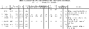
Accompanying the written description was a summary chart (see Table 4); it would be interesting to know who made up this chart and who checked it before printing because the information in it barely lines up at all with the text description! For example, the chart claims that on 5 May the engine broke its crankshaft yet three days later it completed a 6 hour run! Then just three days after that, it completed a 9 hour 16 min run, which wasn't required by the rules of the competition at all!
Table 5 is a summary of the information provided under the heading "Trials" compiled by the author. The unfortunate aspect of the Argyll engine was its weight. It wasn't the heaviest engine in the competition but at 550 lbs (ex radiator), the 120 hp it produced resulted in a lb-per-hp ratio of 4.58, the worst figure of all the entries. If production had gone ahead, a weight reduction program would have been a high priority with aluminium junk heads and pistons in place of the steel variety a possibility. With a stronger crankshaft allowing an increase in revs to 1,400 (about the limit for propellers in those days) a respectable 145 hp should have been attainable.
 |
 |
The Sleeve Drive Mechanisms This is an aspect of the development of both the Burt and the McCollum engines which seems to have caused a lot of thought and experimentation from both inventors. They tried many different variations and even after that, changes by Continental, Bristol and finally Napier were introduced. The Demise of Argyll At the end of the 1914 engine competition, the Argylls Ltd team packed up and returned to Scotland with their two test engines (and three broken crankshafts!). It would have been a sad homecoming not only because of the competition results but also they knew that, due to the precarious financial state of the company, its shut-down was imminent. This occurred on 17 June, 1914. However, the Argyll name and the sleeve valve engine refused to die. As far as aero-engines were concerned, there was interest from the Royal Aircraft Factory, which not only offered Argylls a contract to build engines for them but also were keen to develop other sleeve valve engines using their expertise. The proposed aero-engine contract came to nothing but a V-12 sleeve valve engine based on the R.A.F. production model was built. |
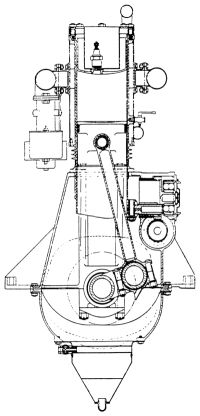
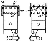
| Fig. 5. Transverse Section of the 120 HP Argyll Sleeve-Valve Aero-Engine. The little tap on the right side of the cylinder is a decompression valve. | Fig. 6. Sketch Showing Relative Positions of the Sleeve, Ports and Cylinder in the McCollum Engine. 17=inlet ports, 18=exhaust ports, 28=sleeve valve. | |
 |
 |
|
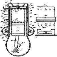
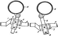
| Fig. 7. Later Version of the McCollum Engine. Note the sleeve is still exterior to the cylinder but movement is controlled from the base of the sleeve, not the top. | Fig. 8. The Prototype Burt Sleeve-drive Mechanism- with Wabble Crank and Sliding Pins |
References
Patents:
GB 190918,140 Burt
GB 191510,304 Burt.
GB 190914,629 McCollum
GB 190927,327 McCollum
US 1198061 Sargent, 1914
British War Office. Doc. #87/1545 1913.
British War Office. N.&M.E.C. Judges' Report 1914.