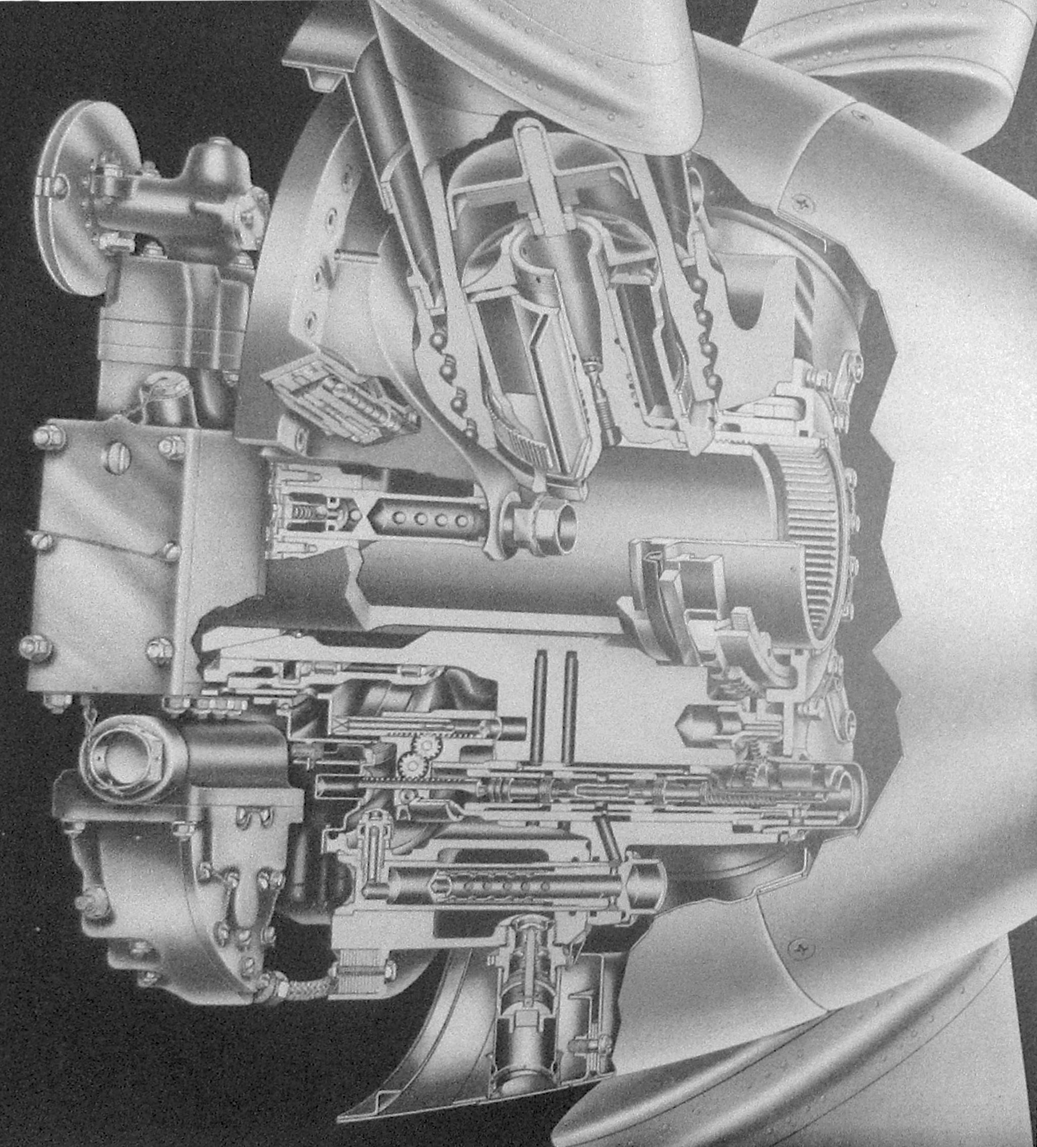
Fig. 0. Model 4260
Super-Hydromatic Propeller
Hamilton Standard Super-Hydromatic Propellers
Part 2: Mechanical Descriptions
by Tom Fey
Published 11 Jun 2018; Revised 9 Sep 2026
Fig. 0. Model 4260 Super-Hydromatic Propeller |
The following analysis is based predominantly on the recent discovery of the Super-Hydromatic Manual #150, dated June 11, 1945, held by the John Ramsay Library of the New England Air Museum, Windsor Locks, CT, USA. This manual describes the Model 4260 single rotation Super-Hydromatic propeller. The author has integrated this information along with that from the progress reports from the National Archives, sections from the Erection and Maintenance Handbook for the Northrop XB-35, and a fortuitous drawing from The Fedden Report to describe the dual rotation Super-Hydromatic propeller. Any errors in fact or supposition are entirely my own. — Tom Fey |
The Single Rotation Model 4260 Super-Hydromatic Propeller
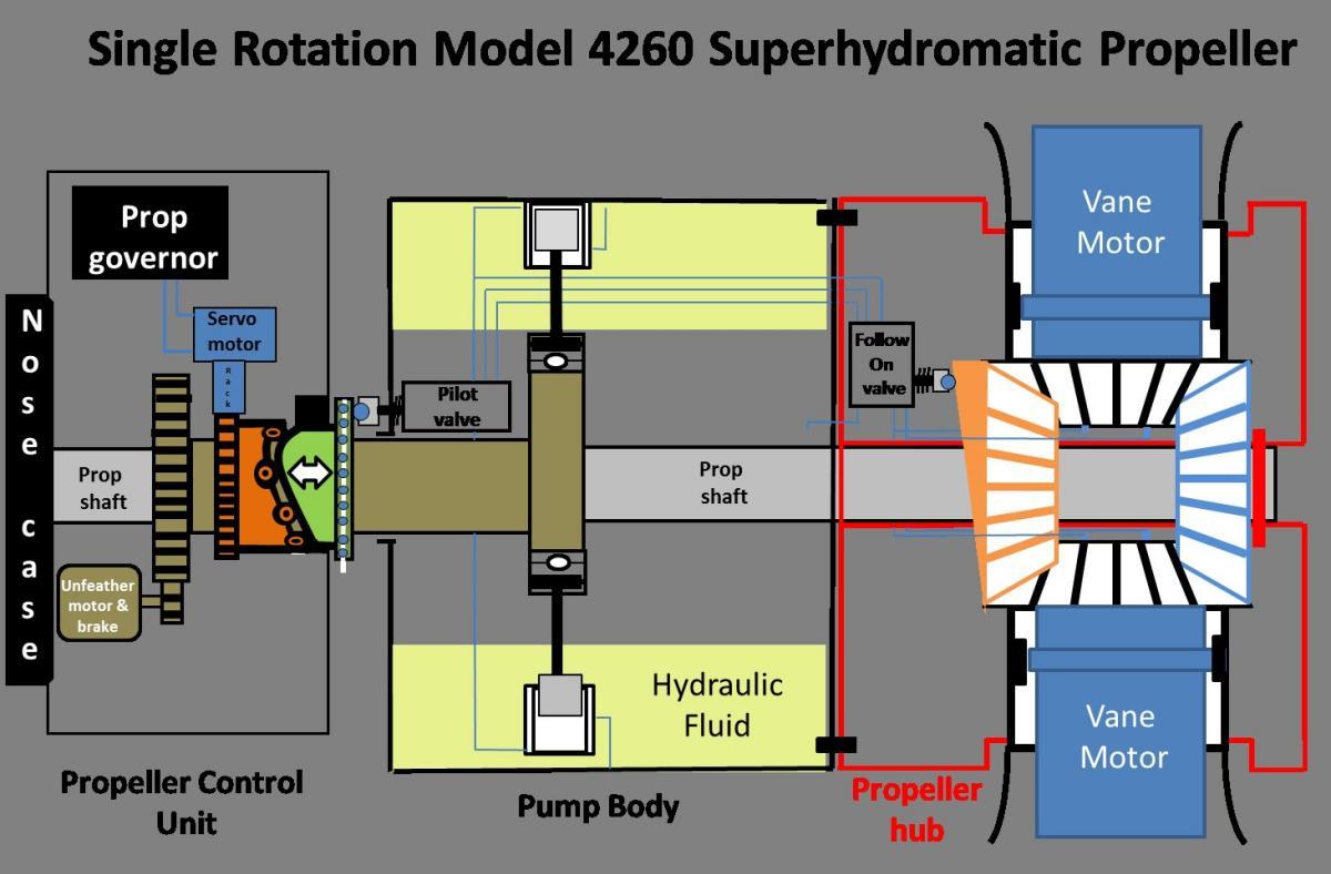
The designation “4260” describes a 4-blade propeller with a number 2 -sized blade shank and a hub receiving a SAE 60-spline propeller shaft (Fig. 0). Figure 8 shows the basic Super-Hydromatic operational schematic. A more detailed component breakdown is shown in Figure 9.
1) Constant SpeedDe-icing was engineered into the design but was not installed.
2) Feathering
3) Reversing
4) Fixed pitch
5) Manual Pitch Changing, and
6) Pitch Indication for the propeller system.
 |
 |
 |
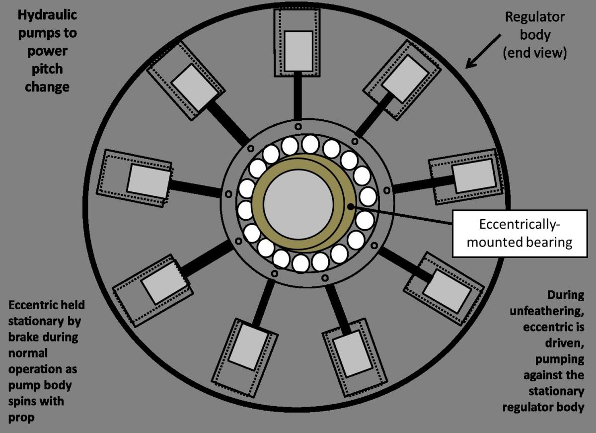 |
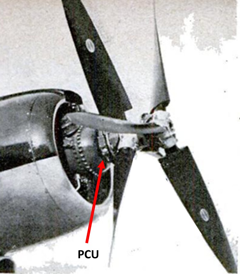
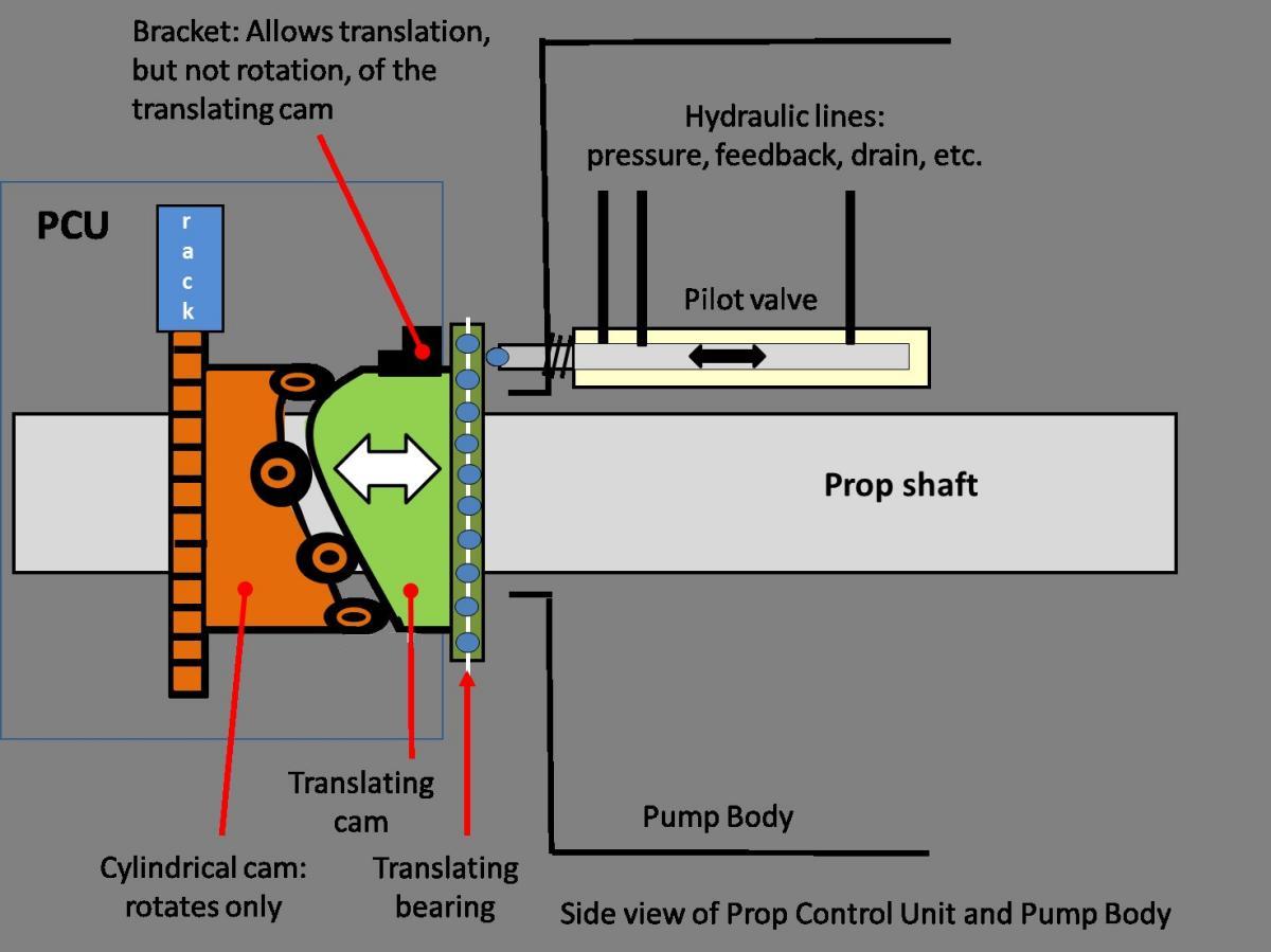
| Fig. 7. Hamilton Standard Super-Hydromatic dual rotation propeller set on the modified, R-2800 powered Douglas B-23 test aircraft. Note the annular Propeller Control Unit (PCU) nestled between the nose case and the propeller. | Fig. 8. Simplified Single Rotation Super-Hydromatic Propeller Operating Diagram | Fig. 9. Single Rotation Super-Hydromatic Propeller Four Major Components | Fig. 10. The PCU with all its electro-hydro-mechanical complexity was housed in a remarkably compact unit that used only 8 ounces of hydraulic fluid. The balancing of the numerous hydraulic circuits was essential for smooth operation. |
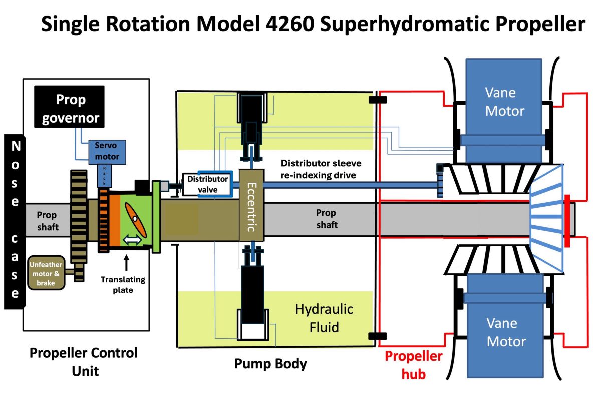
Referring to the schematic diagram in Figure 8, the centrifugal propeller governor regulates oil flow to a servo motor that moves a spring-resisted toothed rack positioned at right angles to the propeller shaft. This rack engages teeth machined onto a cylindrical cam such that movement of the rack rotates the cam, and the cam translates a circular control plate (Fig. 10 #36) either fore or aft along the axis of the propeller shaft. This non-rotating, but translating plate is the mechanism by which a pitch change signal is transferred from the stationary PCU on the nose case to the rotating propeller assembly. Every axial position of the translating plate (and thereby the interfacing distributor valve) corresponds to a specific blade pitch setting. (Fig. 11) The distributor valve (Fig. 8 #7) is located in the propeller hub. Referring back to the schematic diagram in Figure 8, the inboard-facing stem of the spring-loaded distributor valve (Fig. 8 #7) has a bronze shoe that rubs directly on the non-rotating translating plate (Fig. 10 #36). When the translating plate moves, the distributor valve is displaced, and the distributor valve directs the oil flow to one side or the other of the hydraulic vane motors to change the blade pitch to the commanded setting. Once the blades start to move to the desired pitch, a mechanical linkage from the base of the propeller blade to the sleeve encircling the distributor valve repositions the sleeve axially around the distributor valve, re-indexing the system to achieve a new stabilized “onspeed” condition and and hydraulically locking the blades in place (Fig. 12; Fig.13) Because of the required geometry and packaging constraints of the various distributor valve system components, the distributor valve is actuated through an offset rack-and-pinion gear train that allows the “surrogate stem” of the distributor valve to interface on a the smaller-diameter translating plate, which also lowers the rubbing speed of the bronze shoe on the translating plate. The distributor valve assembly itself is located in the hub on a radius perhaps an inch or two larger than that of the translating plate. (Fig. 13) The hydraulically-balanced design of the distributor valve means it takes relatively little force to move the distributor valve.
So where does the Super-Hydromatic obtain the hydraulic power to turn the propeller blades on their axis? The answer is a radial-type, multi-cylinder hydraulic pump located in the pump body. (Fig. 14) The pump configuration is not unlike a rotary engine. The link rods pegged to the pistons have large rolling wheels on their ends that ride on an eccentric at the center of the pump body. The eccentric is a concentric sleeve located between the propeller shaft and the translating plate assemblies. It is held stationary by the (braked) unfeathering motor, and the link rods, pistons, pump cylinders, and pump body all orbit around the locked eccentric. The pump body is partially filled with its own dedicated supply of hydraulic fluid, and the centrifugal force of the rotating pump body throws hydraulic fluid outward to feed the intakes of the hydraulic pumps. There are nine individual pump assemblies, each with a cylinder bore of 0.5", a stroke of 0.375". With an operational speed of say 1,500 rpm, the pumps provide 4.3 US gallons per minute at 3,000 psi and no need for an accumulator.
The Super-Hydromatic propeller was designed to have very rapid pitch change rate of up to 35° per second, which necessitates a large hydraulic flow volume. The inspired design of the radial pump satisfies both criteria: small diameter hydraulic pump cylinders and pistons to provide the high pressure, and a large number of pumps to supply the required flow volumes. It was hoped that a propeller with such a rapid pitch change rate could be used for aerodynamic braking on the ground and potentially in the air and would lend itself towards future use in high horsepower, constant-speed turboshaft engines.
 |
 |
 |
 |
| Fig. 11. A closer look at the hydraulic control circuits in the PCU. The wizardry shown here resulted in the movement of the translating plate outboard (forward) which in turn moves the distributor valve outboard, sending pressurized oil to the increase-pitch side of the blade vane motors. | Fig. 12. The distributor valve system receives the pitch change signal from the translating plate to direct the hydraulic flow to the pitch change vane motors. As the blades move to their new pitch, a feedback gear train and cam moves the sleeve surrounding the distributor valve to re-index the valve and sleeve to an “on-speed” condition where the blades are hydraulically locked in place. | Fig. 13. Colorized cutaway of the hub showing the distributor valve system as well as the lubricating, pitch-changing, and sump return oil flows in the propeller hub components. | Fig. 14. The pump body with 8 radial pumps driven by the rolling elements riding a stationary eccentric (#46) as the pump body rotates with the propeller hub. The hollow bolts (#55) that secured the pump body to the propeller hub functioned as oil galleries and pressure relief valves. |
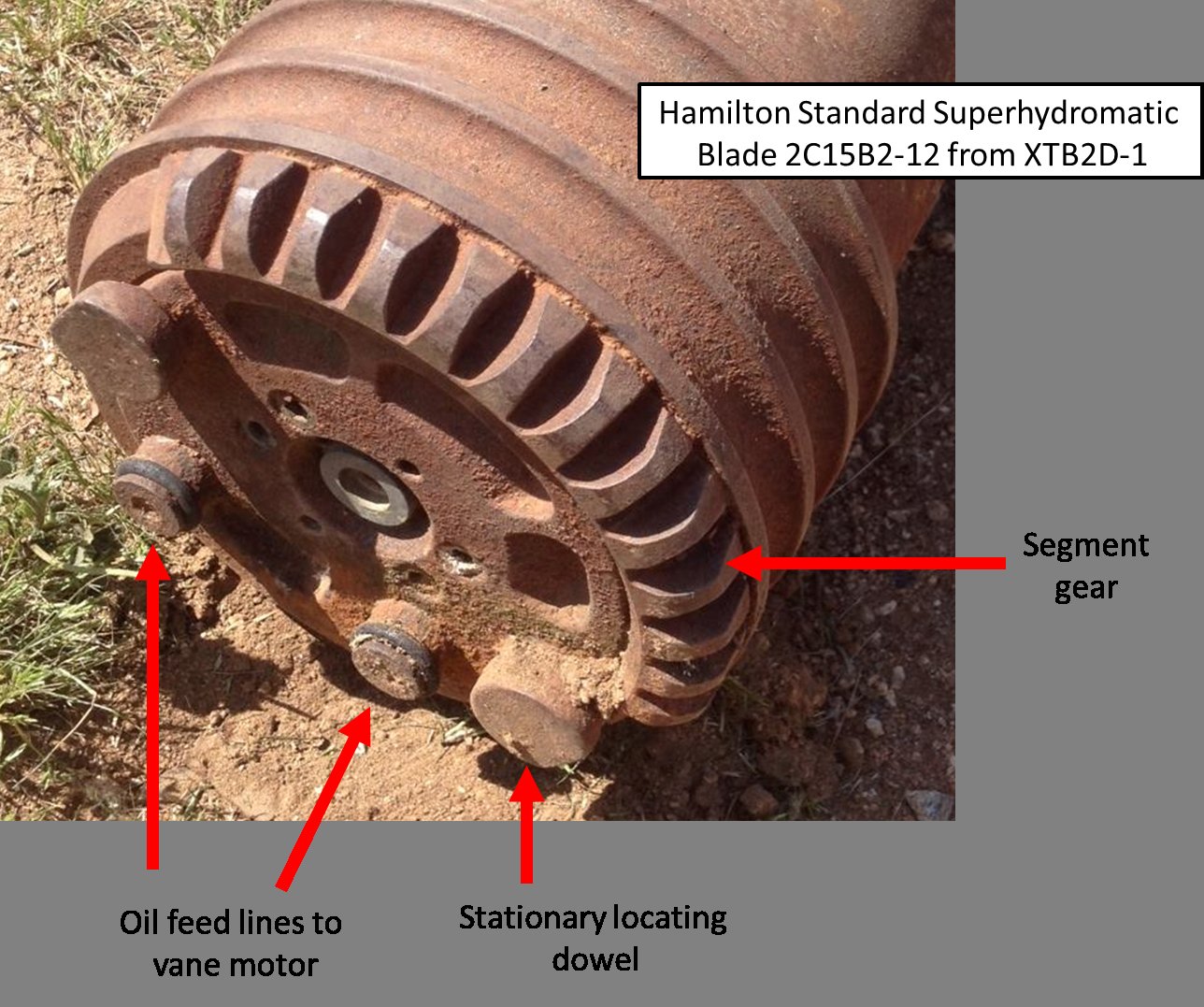
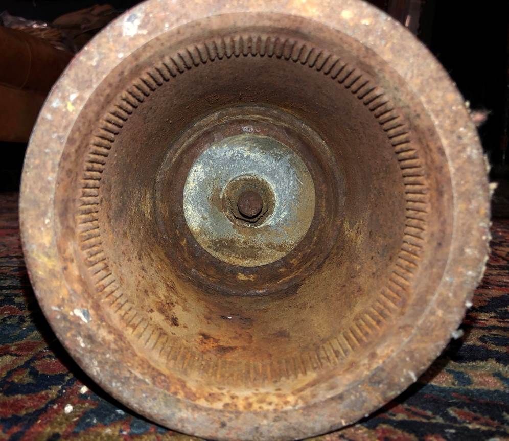
To turn the propeller blades on their axes in the hub, each of the spar-less, hollow steel blades had a hydraulic vane motor assembly slipped into the hollow shank of the propeller blade. (Fig. 15) Internal splines (120 of them) were machined into the propeller hub internal bore to mate with external splines on the vane motor assembly. (Fig. 16) A segment gear attached to the splined, rotating external housing of the vane motor meshes with a circular synchronizing gear to coordinate the movement of all the propeller blades in the hub. Interestingly, the synchronizing gear was composed of three segments with very fine gear teeth that allowed individual blade pitch to be adjusted down to 0.06° to compensate for manufacturing or aerodynamic differences among the blades. (Fig. 17).
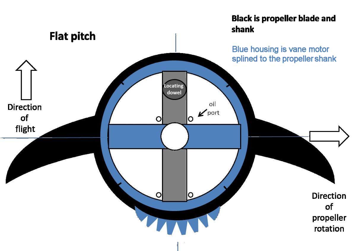
The hydraulic vane motor was a four-chamber design and very similar to the central vane motor of the Canadian Hoover hydraulic propeller. The stationary “wall” indicated in gray was pegged to the hub via a dowel pin, and the moving rotor “walls” were integral to the external vane motor housing. (Fig. 18) As controlled by the distributor valve, two chambers were expanded with pressurized fluid while the other two chambers were vented to the pump body, and this produced the rotation of the motor housing and propeller blades. (Fig. 19) Vane motor seals were of an unknown design and material.
 |
 |
 |
 |
 |
| Fig. 15. Vane motor assembly components seat in the blade shank hollow core. | Fig. 16. Super-Hydromatic blade hollow base showing the 120 engagement splines that mesh with the vane motor. | Fig. 17. Super-Hydromatic 2C15B2-12 propeller blade base as used on the Douglas XTB2D-1 Skypirate. The vane motor is inserted in the propeller blade hollow shank. The vane motor hydraulic supply nipples can be seen with rubber O-rings still on them. The vane motor external housing engages internal splines on the prop blade, and the segment gear is integral to the vane motor external housing. | Fig. 18. Super-Hydromatic propeller vane motor schematic. The central gray “wall” component is secured to the propeller hub by the locating dowel and does not move. | Fig. 19. Super-Hydromatic propeller vane motor schematic after a pitch change has been commanded. The red quadrants have been filled with pressurized hydraulic fluid, turning the blade while the white quadrants are vented to the fluid sump. |
Instead of the traditional bearing stacks, the steel blades had bearing races machined directly into the hardened blade shanks with the opposing race machined into the propeller blade barrel (socket) internal diameter. (Fig. 20) The blade assemblies with their internal vane motors were slipped deeply into the barrel and then the ball bearings were fed into the races through holes bored in the hub. The blade was then pulled out slightly from the hub to seat the bearings, the entry holes capped, and the top of the barrel sealed with a cover plate.
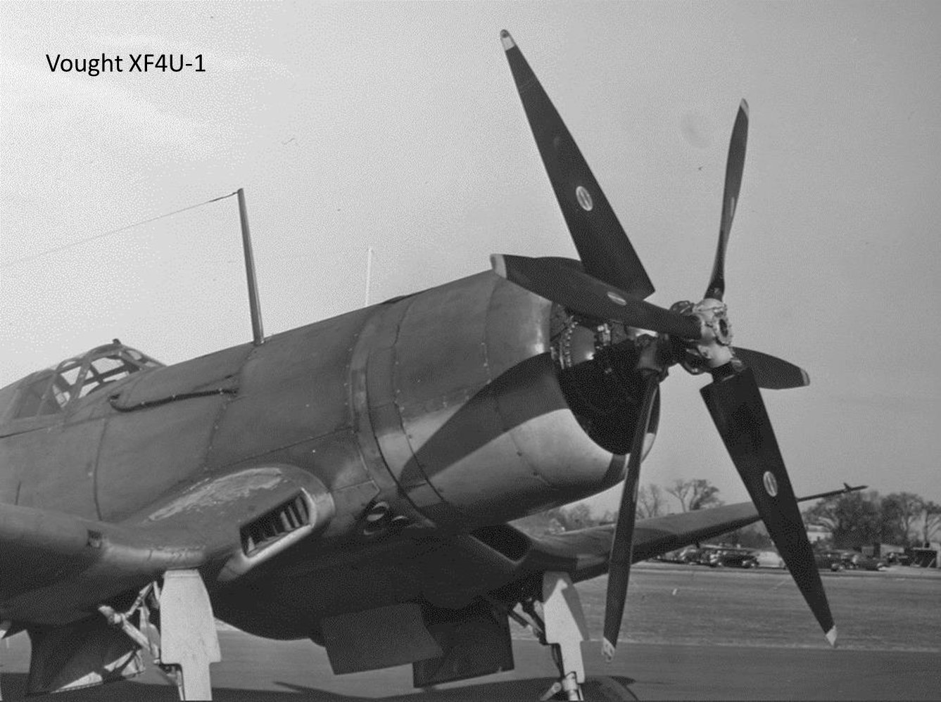
The single rotation Super-Hydromatic 4260 propeller passed its 110-hour type test in June 1944. It was being test flown on a F4U-1 Corsair and F6F Hellcat during February 1946 when excessive loss of propeller hydraulic fluid to the engine nose case was noted and a seal was requested by the military. Hamilton Standard replied that such a seal would affect the fundamental design of the propeller, and that they were working on the problem. (Fig. 20AA)
 |
 |
| Fig. 20. Individual blade ball bearings are fed into the hub in the left-hand photo. Once the prop blade is loaded, the ball bearings seat themselves against the outboard races. | Fig. 20AA. Simplified color schematic showing the Model 4260 Super-Hydromatic propeller major components. |
Mechanical Description of the Dual Rotation Super-Hydromatic 828060 Propeller
1) a translational signal to the outboard distributor valve to select blade pitch and
2) a “stationary” fixation point for the outboard oil pump eccentric around which the hydraulic pumps can orbit to generate pressure. (Fig. 22)
The Dual Rotation Super-Hydromatic Propeller: The Fedden Mission Drawing
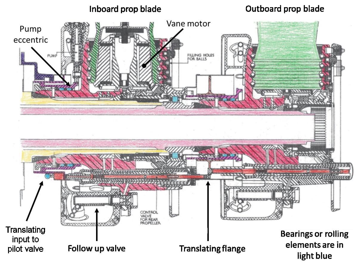
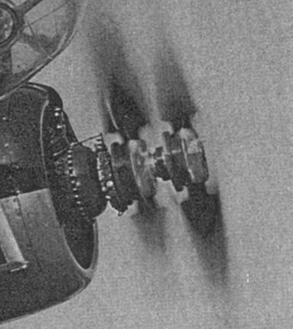
As can be discerned from the Super-Hydromatic timeline, there was at least a decade of development that went into the propeller, and likely a number of substantive changes to the design as problems arose. By December 1942, the Super-Hydromatic design had been under development for at least three years. The dual rotation Super-Hydromatic drawing in the Fedden Report shows perhaps an early version of this propeller, and this single drawing remains the only discovered document that shows the internal configuration of the dual rotation Super-Hydromatic propeller.
1) Although hydraulic fluid paths are not described, it appears from the drawing that gaps between the propeller shaft and the propeller hub and/or pump body were used as galleries to conduct hydraulic fluid between components. While a clever and perhaps unavoidable necessity of the design, proper sealing between the fore and aft propeller components, as well as between the concentric propeller shafts, and the engine nose case were both essential and highly problematic under the 3,000 psi working pressure.
2) There are no offset rack-and-pinion gears for the either the inboard or outboard distributor valves.
3) The vane motors have a lot of edge surface area to be sealed against 3,000 psi of hydraulic pressure.
 |
 |
 |
 |
 |
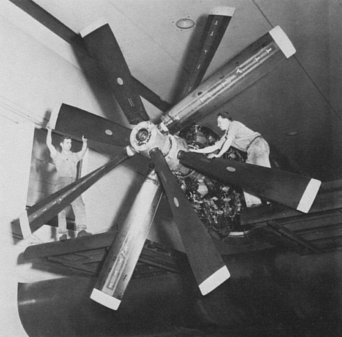 |
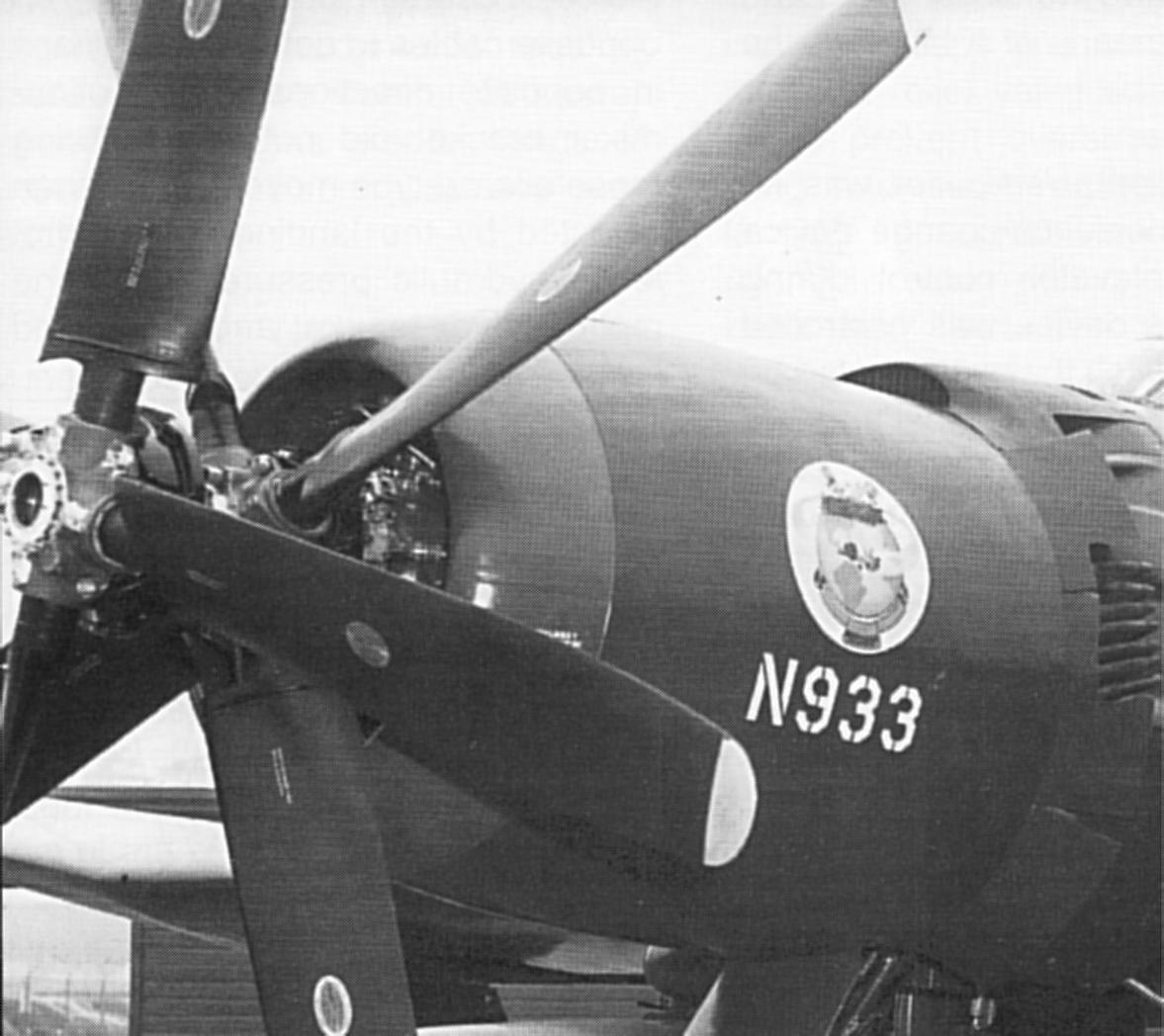
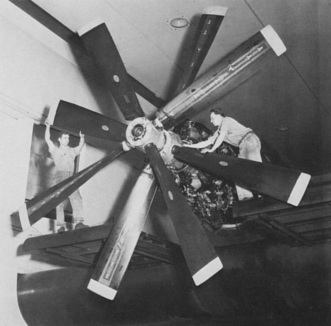
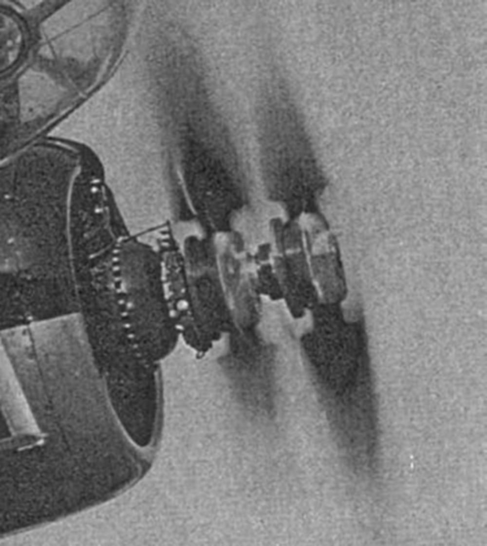
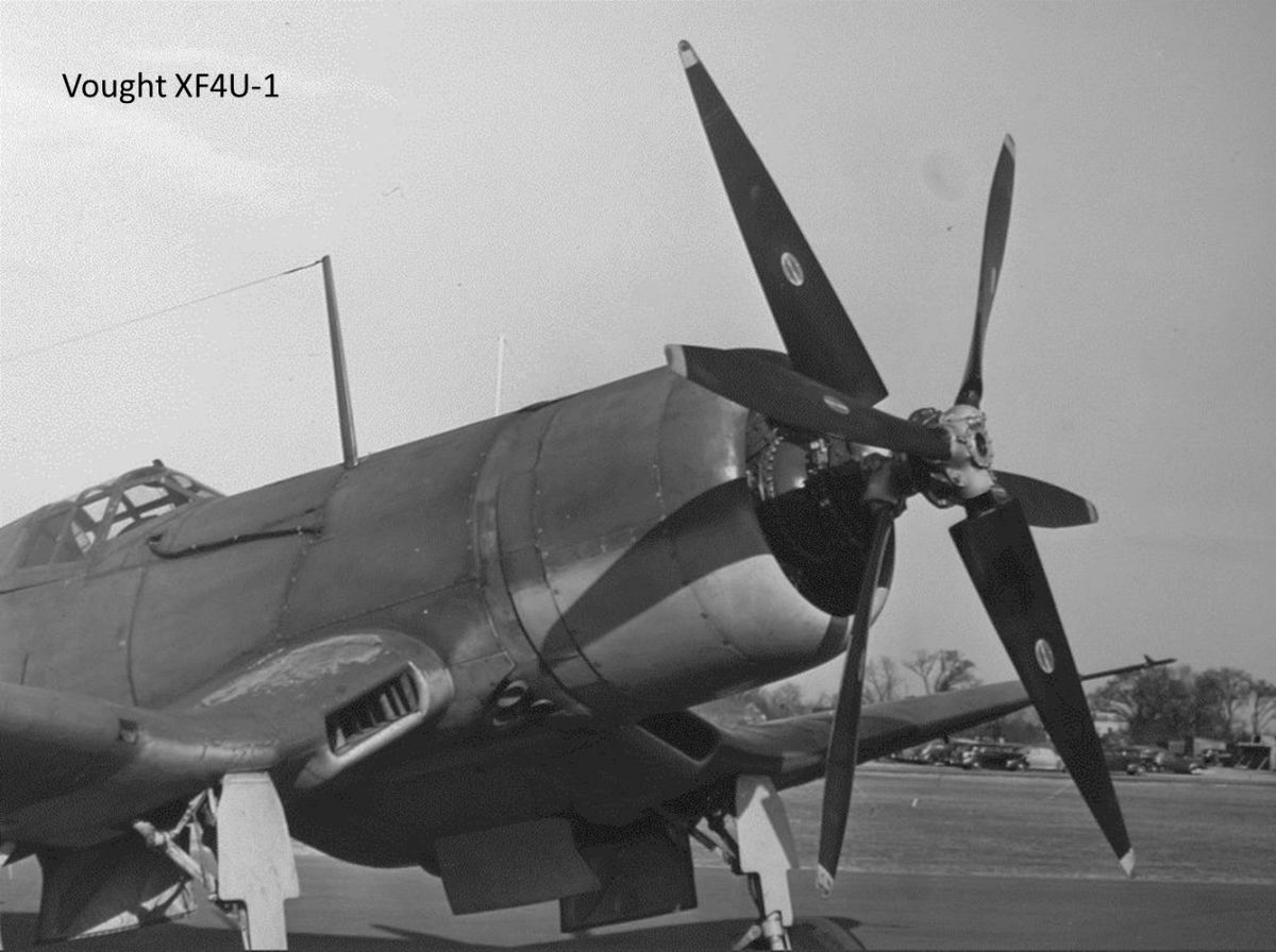
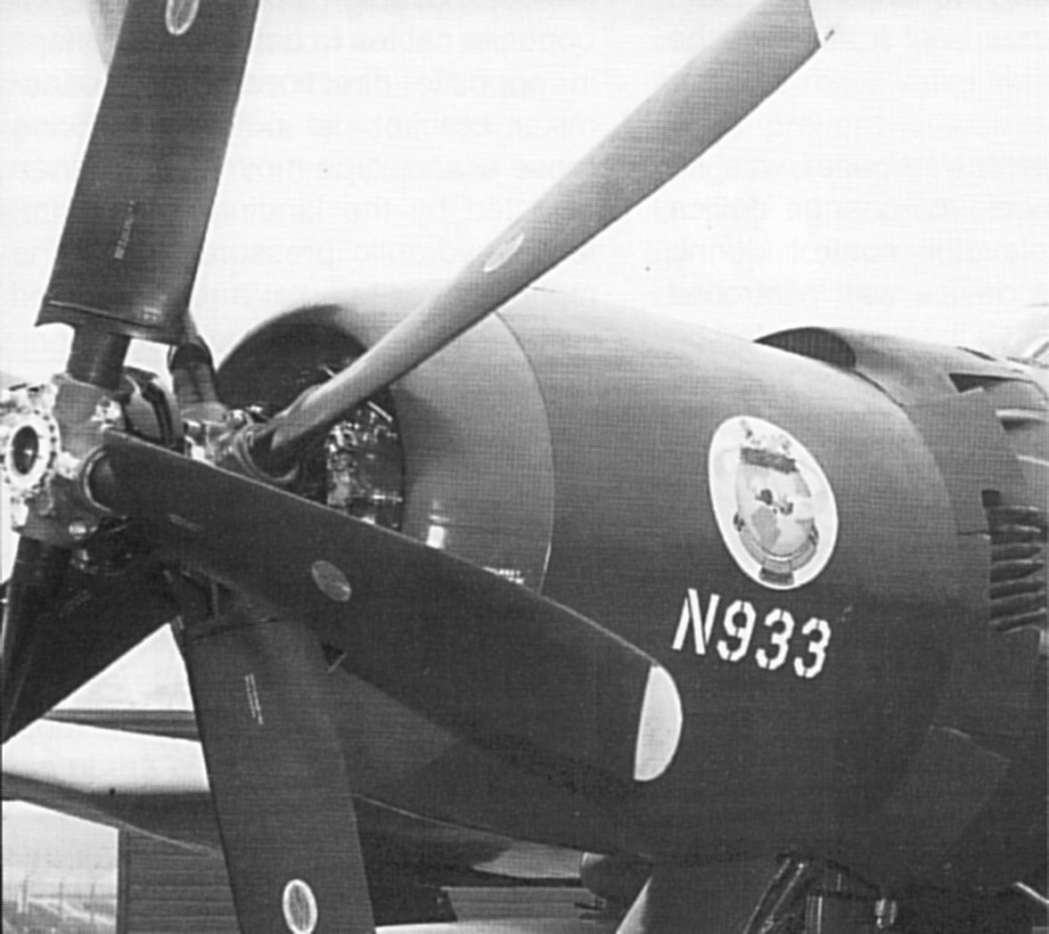
| Fig. 21. The only known drawing of the Hamilton Standard Super-Hydromatic dual rotation propeller from the Fedden Mission to America report published December 1942. Of note are the gaps between the propeller shafts and the pump body as well as the gaps between the propeller shafts and the propeller hubs which may have functioned as galleries for the hydraulic fluid. The bore of the propeller was empty. | Fig. 22. Simplified color schematic showing the dual rotation Super-Hydromatic propeller control system outboard components. The inboard component (spins counter-clockwise viewed from aft) and outboard component (spins clockwise VFA) are diagrammatically separated by the blue dotted line. The inboard distributor valve directly controls the outboard distributor valve through the interstitial translating plate. | Fig. 022A. “Early” Model 624060-1 Super-Hydromatic dual rotation mounted on the Douglas B-23 test ship. Note the slender pump bodies and possible control rod or cable extending from the upper engine nose case to the PCU. | Fig. 022B. Six-blade Model 624060 Super-Hydromatic dual rotation propeller on the Chance Vought XF4U-1A Corsair with dual rotation nose case. Note the cable bundle running on the fuselage exterior between the engine accessory section and the cockpit. | Fig. 022C. Eight-blade Model 828060 Super-Hydromatic dual rotation propeller on the Douglas XTB2D-1 Skypirate. The propeller hub and pump body appear different in design and certainly size from that seen on the six-blade Model 624060 Super-Hydromatic propeller. | Fig. 022D. Eight-blade Super-Hydromatic in the test cell powered by an R-4360 engine. Two blades of each set are instrumented with strain gauge strips. Note the near constant chord and square tips of these blades. |
Send mail to
 with questions or comments about this web site.