Wright J-5A 100-hour Full-Throttle Endurance Test
Compiled by Kimble D. McCutcheon
Published 4 Jun 2024

Wright J-5 |
Through continuous improvement, Wright Aeronautical Corporation arrived at the J-5 Whirlwind series in 1925, which boasted a new cylinder design and became the first really reliable American air-cooled engine. It sold extremely well and powered a host of new aircraft. In 1928, Wright replaced the J-5 series with a new J-6 Whirlwind series, which added a supercharger and was based on a new 5.000" (127.00 mm) bore by 5.500" (139.70 mm) stroke cylinder displacing 107.99 in³ (1.770 l). This series comprised a five-cylinder Model R540, a seven-cylinder Model R760, and a nine-cylinder Model R-975.
This article describes testing done on a Wright J-5A by the Navy from 28 Apr 1927 to 28 May 1927. By the time this testing was done, Thomas Midgly at the Ethyl Corporation had discovered that tetraethyl lead helped reduce detonation and replaced the benzol used during J-4A testing.
This article was compiled from U.S. Navy Bureau of Aeronautics Report No. AEL-183 dated 15 Jul 1927, part of U.S. National Archives at College Park, Maryland Record Group 72 Entry 95 Box 7. Excerpts from an earlier article on the Wright J-5 were also used. |
Object
This test was to determine the durability of a Wright Model J-5A engine, operating without detonation, during a 100-hour full-throttle non-stop run.
Resume
Results from the preliminary full throttle runs indicated that 2cc of Ethyl Fluid (tetraethyl lead) per gallon of domestic aviation gasoline (hereinafter D.A.G.) was sufficient to suppress detonation. This fuel was used for the endurance run.
The endurance test was terminated when the No. 3 exhaust valve failed after 109.3 hours full-throttle running. Three stops were made during the run that were not attributable to the engine. The first was an involuntary stop caused by a faulty fuel supply. The second was made to prevent damage due to the failure of three test club bolts. The third was made to prevent a possible fire due to broken primer tubing connection at the main fuel line. No engine adjustments were made during the endurance run except to the "Uniflow" rocker arm grease cups and rocker box cover screws. The longest non-stop period was 62.4 hours.
During the run, the average rpm was 1,751, the average hp was 214, fuel consumption was 0.54 lb/hp/hr and oil consumption was 0.023 lb/hp/hr. The results were remarkably consistent.
The principal engine failures were:
- The No. 3 exhaust valve broke off at the junction of the head and stem.
- The exhaust valve seats were in bad condition and were coated with a dark colored deposit. Nos. 1 and 9 exhaust valve seats were recessed approximately 0.063"
- Nos. 1, 3, and 6 exhaust rocker arms were striking against the push rod housing.
- The master rod bearing babbitt broke loose in two spots.
- Three rocker box cover screws broke and nine came loose.
- Six valve tappet roller pins broken and one cracked.
- The No. 9 exhaust rear rocker stud broke.
- The No. 9 exhaust rocker roller was flat on one side.
- The No. 1 exhaust rocker arm bearing was cracked.
- Nine rocker arms were striking the rocker box covers.
- Core sand was found in one of the cam follower bosses.
- The cam driving gear was worn.
- Some of the push rod ends were badly worn.
Conclusions
- Examination of the engine indicated that in general it was in remarkably good condition considering the severity of the test.
- The Aeronautical Engine Laboratory's experience with operating J-5 and J-5A engines indicates that the exhaust valve failure was due to material defect either in the valve or valve seat, rather than design, and that the failure of the master rod bearing was probably due to poor babbitt rather than design.
- The valve seat condition may have been caused by inferior valve seat material, by the attack of Ethyl Fluid, or improper machining.
- The rocker box stud failure was probably due to too tight a drive-in assembly.
- Cam drive gear wear was caused by insufficient hardness.
- Rocker box cover screw failure was due to the inability to tighten the screws against the nut without buckling the cover.
- Push rod end wear was responsible for the rocker arms striking push rod housings.
Recommendations
- The long nuts that engage the rocker box cover screws should be lengthened so that the cover screws can be pulled up snugly against these nuts without buckling the cover.
- Inspections should be more thorough
- The crankshaft gear should meet the required hardness specifications.
- The rocker box studs should be necked to prevent thread twisting during assembly.
- A method for continuous rocker arm bushing lubrication should be provided.
- The clearance between the rocker arm and push rod housing upper end should be increased or a new design should be adopted.
- The valve tappet roller pins should be made stronger.
Description
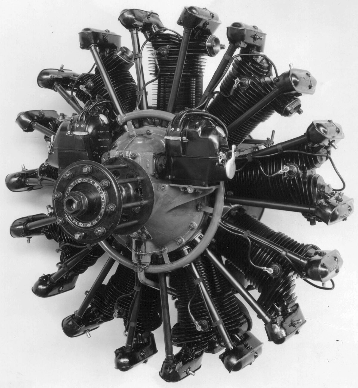
The Wright Aeronautical Corporation, located in Paterson, New Jersey, built the Model J-5A air-cooled 9-cylinder static radial. With a 4.500" (114.3 mm) bore, 5.500" (139.7 mm) stroke, 787.26 in³ (12.901 l) displacement and 5.38:1 compression ratio, it was rated 200 hp at 1,800 rpm.
The J-5A single-throw one-piece crankshaft was 29.187" (741.35 mm) long, its main journal outside diameters were 2.590" (65.79 mm), its main journal inside diameters were 1.386" (35.20 mm), and its journal sectional torsional modulus was 3.13 in³ (79.50 mm³). Its crankpin outside diameter was 1.998" (50.75 m), its inside diameter was 0.8175" (20.64 mm), and its torsional section modulus was 1.52 in³ (30.61 mm³). Its crank cheek torsional section modulus was 0.717 in³ (19.21 mm³). The crankshaft was supported by two single-row ball main bearings and one single-row deep-groove thrust bearing. A propeller hub was not furnished.
The H-section master connecting rod, forged from chrome nickel steel, was 10.873" (276.17 mm) from center to center. The eight tubular-section articulated rods, also forged from chrome nickel steel, were 8.872" (225.35 mm) from center to center. The master rod bearing was steel-backed babbitt. The knuckle pin bushings and piston pin bushings were bronze.
The rocker arm bushings were bronze, the intake valve guide was aluminum bronze and the exhaust valve guide was steel.
The ribbed pistons were cast from Y-alloy, composed of aluminum, copper, nickel and magnesium. Three compression rings were located above the piston pin and an oil scraper ring was located at the skirt bottom. The hollow piston pins were machined from either SAE 3250 or 1100X steel, which was hardened in oil and annealed before machining. They were retained by aluminum plugs inserted in the ends.
The cylinder assemblies consisted of 13-fin aluminum alloy heads that were screwed and shrunk onto to forged steel barrels with 13 machined fins and hold-down flanges. The combustion chamber was approximately hemispherical with the valve axes inclined to the cylinder axis at 35° angles. Two bronze spark plug bushings were screwed and pinned at locations diametrically opposite one another 10° to the crankshaft axis. Two extruded aluminum bronze rectangular-section valve seats were shrunk into each cylinder head. Two 45° seat tulip-type valves were in each cylinder. The solid-stem intake valves were made from SAE No. 7260 tungsten-chromium steel, had a 2.36 in² (1,523 mm²) clear area and 1.875" (47.63 mm) port diameter. The hollow-stem exhaust valves, made of SAE No. 71660 or 71360 tungsten-chromium steel, had a 2.28 in² (1,471 mm²) clear area, 1.813" (46.04 mm) port diameter, and salt-cooled stems. Lift for both was 0.5" (12.7 mm), both had a 2.125" (54.0 mm) outside head diameter, and both employed three helical springs wound from round wire.
The intake valves opened at 8° BTC and closed at 60° ABC; the exhaust valves opened at 60° BBC and closed at 8° ATC. Running clearance was 0.060" (1.52 mm) hot and 0.040" (1.02 mm) cold for both. Valve timing could be adjusted via a clutch on the countershaft directly above the crankshaft that allowed changing the relative positions of the countershaft gear and pinion.
The cam gear consisted of a hardened steel ring with two cam tracks, one for intake and one for exhaust. Each track had four cam lobes. An internal gear was driven at 1/8 engine speed opposite the crankshaft direction via a countershaft. The ring was riveted to an aluminum alloy hub that rode on a steel sleeve on the crankshaft. Cam followers with rollers were carried in the intermediate crankcase section surrounding the cam; and from these the valves were actuated through push rods and rocker arms. The cam base circle diameter was 9.250" (234,95 mm). inches.
Two Scintilla V-AG9-D magnetos (Nos. 0303 and 0306) were mounted on the front crankcase section. The right magneto fired the front spark plugs and the left magneto fired the rear plugs. Normal ignition timing for both magnetos was 30° BTC. Firing order was 1-3-5-7-9-2-4-6-8.
The single Stromberg NA-T4 carburetor had a 1.438" (36.5 mm) venturi, #51 main jet, #55 main jet air bleed, #60 idle jet, #39 idle air bleed, 0.250" (6.35 mm) accelerator well bore, and a 1.125" (28.6 mm) below the parting line float level when using D.A.G. Altitude mixture control was accomplished via suction on the float chambers.
The starter was an Eclipse inertia Model 1900 B, Series 6, No.248.
The intake manifold formed the aft portion of the crankcase main section. Comprising three annular rings, each of which supplied fuel/air mixture to three cylinders through steel intake pipes, the mixture was fed from the carburetor into an oil-jacketed manifold at the crankcase main section bottom, and from there to the annular rings.
The cast aluminum-copper alloy crankcase consisted of a front section, intermediate section, main section and rear section.
The gear-type oil pump consisted of two scavenge pumps and one pressure pump, driven as a unit from the accessory drive housed in the crankcase rear section.
The fuel pump, supplied by Viking, had a composition gear meshing with a steel internal gear, running at crankshaft speed.
Uniflow grease cups, non-standard equipment supplied by the Cincinnati Ball Crank Co, had a 0.063 oz grease capacity and allowed the rocker arms to run longer between servicing intervals.
The full pressure lubrication system pressure pump drew oil from an external tank and delivered it to an annular groove around the rear (plain) crankshaft bearing where it entered the hollow crankshaft. Internal crankshaft drillings supplied oil to the connecting rod crank pin bearing, to the cam bearing; and to passages near the crankcase front that led to the magneto drive bearings. Holes through the connecting rod bearing conveyed oil into the passages that carried it into the knuckle pins and from there to the knuckle pin bearings. The various gears, shafts, and bearings in the crankcase rear section were lubricated by oil that sprayed from the rear crankshaft bearing. The cam and magneto drive mechanisms were lubricated by spray from the cam bearing. Cylinders, pistons, and piston pins were lubricated by spray from the crank pin bearing. The rocker arm bearings were lubricated with a Zerk grease gun. No provision was made for lubricating the rocker arm roller at the valve end or the socket joint at the push rod end.
 |
 |
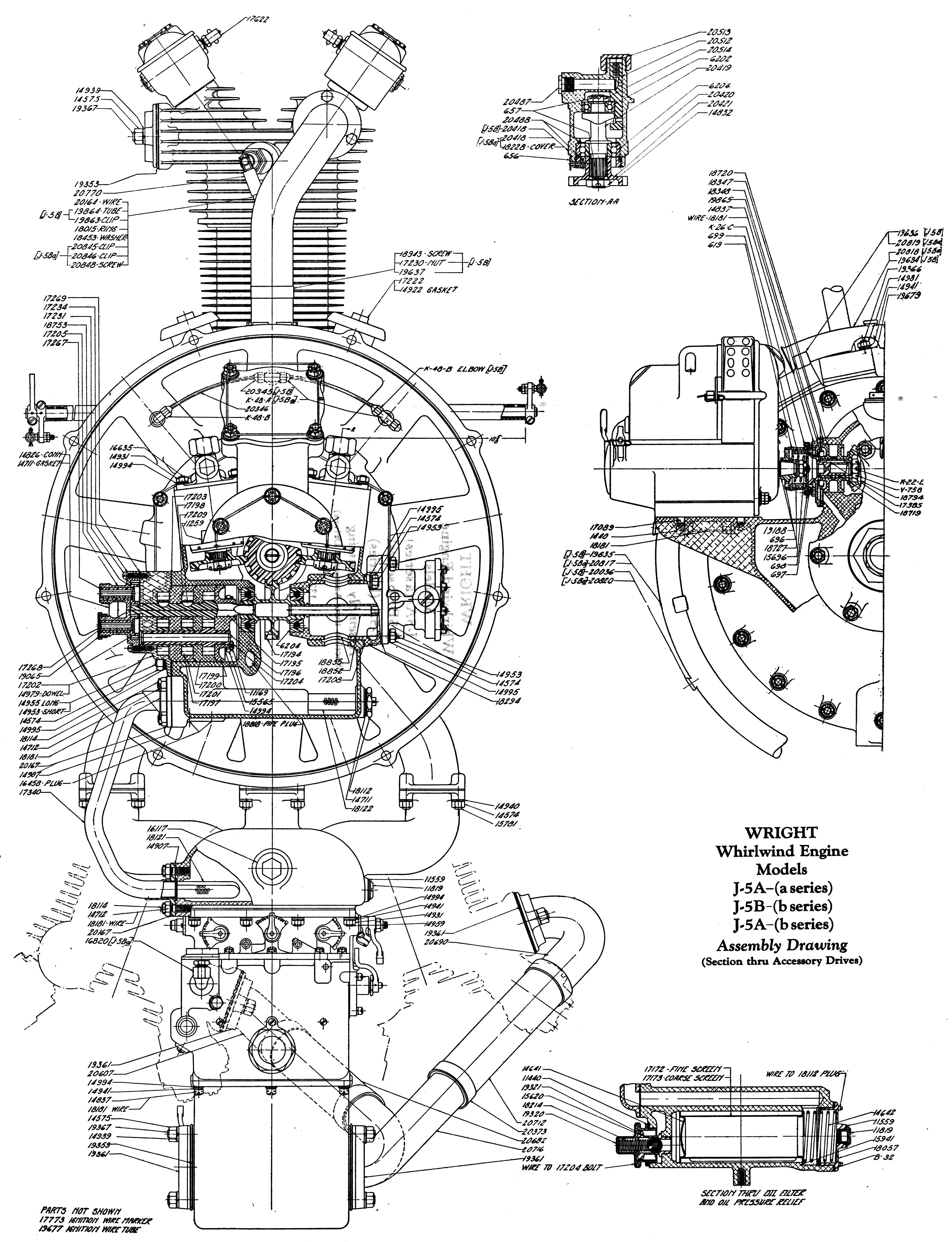
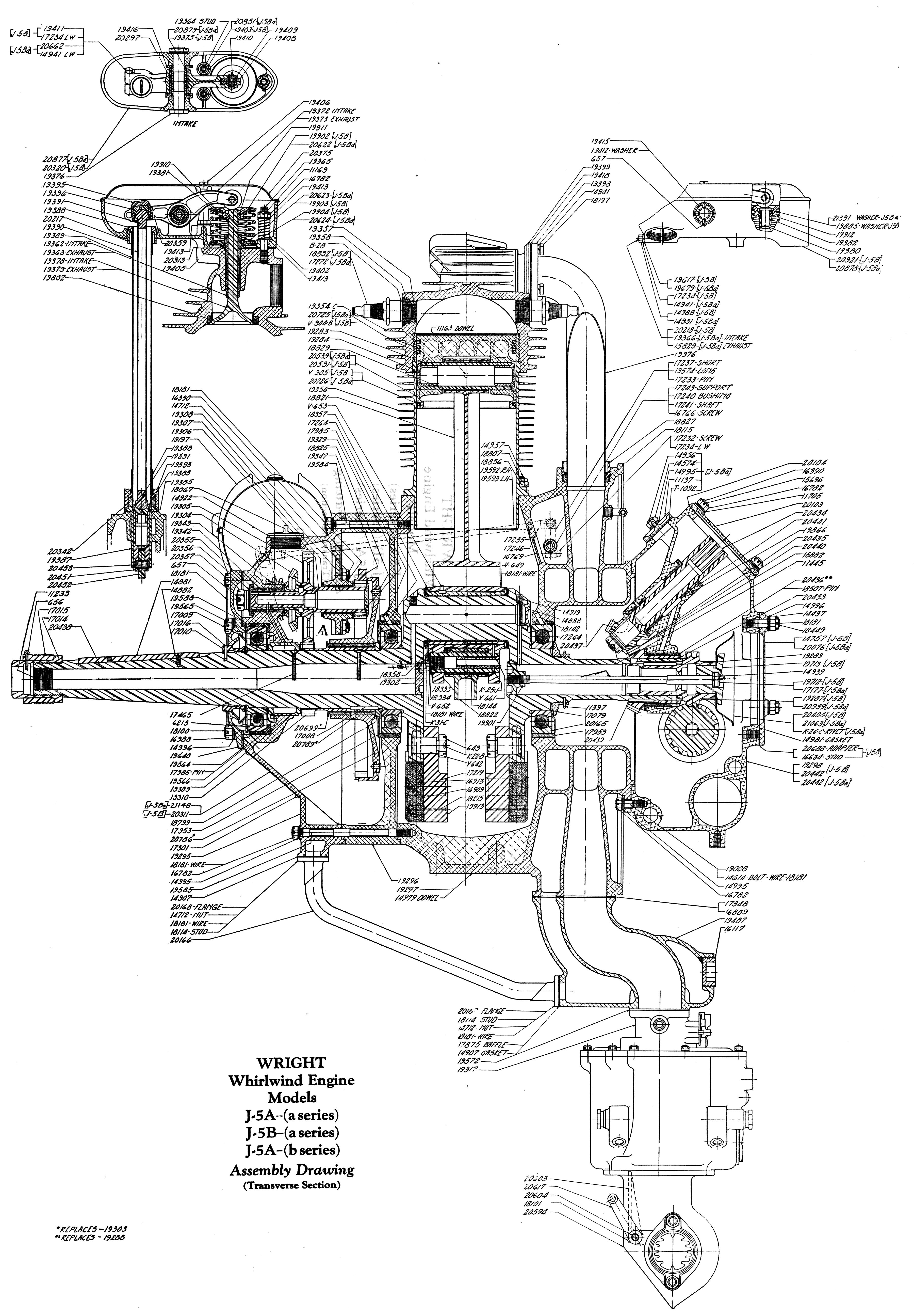
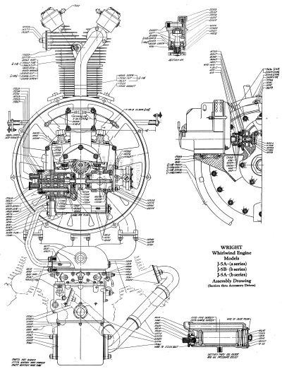
| Wright J-5 Assembly Drawing Showing Parts Placement |
The J-5A basic dry weight was 510 lb (231 kg). Weights of accessories and components are tabulated below.
| Hand Starter and Crank |
22.9 lb (10.39 kg) |
Crankshaft |
51.9 lb (23.54 kg) |
| Hand Starter Crank |
3.7 lb (1.68 kg) |
Master Rod and Bearing |
10.0 lb (4.54 kg) |
| Exhaust flanges including pipes |
7.8 lb (3.54 kg) |
Piston |
1.7 lb (0.77 kg) |
| Tool Kit |
25 lb (11.34 kg) |
Piston Rings and Pin |
0.8 lb (0.36 kg) |
| Fuel Pump |
2.7 lb (1.22 kg) |
Magneto (each) |
14.9 lb (6.76 kg) |
| Oil Pump |
3.3 lb (1.50 kg) |
Carburetor |
11.3 lb (5.10 kg) |
| Cylinder Assembly |
15.3 lb (6.94 kg) |
Link Rod |
1.5 lb (0.68 kg) |
| Rocker Box Assembly |
2.1 lb (0.95 kg) |
|
|
Principal differences between the J-5 and J-5A
- J-5 cylinders had no spark plug bushings; J-5A cylinders had bronze bushings.
- J-5 crankshaft main bearings were Hoffman roller; J-5A used S.R.B. molybdenum steel ball bearings.
- The J-5 rocker box design was slightly changed to allow for J-5A permanent mould castings.
- J-5 cylinder hold down nuts used Palnuts; J-5A used lock washers.
- J-5 primer nozzles were in the cylinder head; J-5A nozzles were in the crankcase intake passages.
- The J-5A omitted the gun synchronizer drive.
- The J-5A had a look ring to retain the push rod adjusting nut socket.
- The J-5 had alemite rocker shaft grease fittings; the J-5A used Zerk fittings.
- J-5 rocker box covers were made from sheet duralumin; J-5A covers were sheet steel.
Test Apparatus Description
This test was conducted on an open air torque stand equipped with a mercury scale for measuring torque. For 72.7 hours, the power was absorbed by a four-blade wooden propeller; for the remainder of the test a two bladed wooden propeller was used. A honeycomb grid was used to straighten the slip stream aft of the propeller. Fuel consumption was obtained by the conventional weight method. The rpm was obtained with a positive revolution counter. The oil .supply tank was mounted on a platform scale and consumption determined from scale readings. All temperatures were measured by carefully calibrated electric-resistance type thermometers. Cylinder temperatures were measured by iron-constantan thermocouples were installed in all cylinder heads just aft of the cylinder plane. The fuel used was mixed in barrels and convoyed to an overhead tank by moans of an automatic pump operated by a float in the overhead tank. A duplex oil strainer, manufactured by the Wright Aeronautical Corporation, was installed in the oil intake line. The pitot tube used for measuring air velocity across the engine was mounted midway between cylinder Nos. 3 and 4 in a plane through the cylinder center lines about 5.125" (130 mm) from the crankcase.
Method of Test
Valve timing, magneto timing, and the clearance volume of cylinder No. 1 were obtained before the engine was mounted on the torque stand. The carburetor main metering jets were removed, flowed and replaced by a set that were within the limits prescribed by the Aeronautical Engine Laboratory. "Uniflow" grease cups with a 0.063 oz volume were installed on all rocker boxes. The engine oil strainer was replaced by the duplex oil strainer to permit cleaning while the engine was running.
Preliminary runs were made to determine the minimum percentage of Ethyl Fluid required with D.A.G. to suppress detonation. After those runs were made all valve tappets were set to the standard clearance of 0.040" (1.016 mm). The clearances between the cylinder heads and the rocker box rears were set to the standard value 0.034" to 0.036" (0.864 mm to 0.914 mm). Oil was drained after this run and new oil added for the endurance run.
The endurance test started with the intention of running continuously for 100 hours. During the run, oil was weighed on a very accurate scale before it was emptied into the supply tank. When the run was over, the remaining oil in the system was removed and weighed. This procedure enabled oil consumption measurement. Fifteen gallons of hot oil was added when necessary. Oil temperature was regulated by steam and water passing over the oil radiator. Readings were taken, calculated and plotted every half-hour. At the end of the endurance test the engine was disassembled, thoroughly inspected, and measured.
After the failure of three propeller bolts, which necessitated changing the propeller, a series of readings were taken with 6 cc Ethyl Fluid per gallon of D.A.G. These readings were compared with runs made with 2 cc Ethyl Fluid per gallon of D.A.G. to see if detonation was present due to the lower air stream velocity with the two bladed propeller.
Method of Calculation
Power Correction: The observed power was corrected to a standard atmospheric pressure of 29.92 inHgA at 59°F carburetor air temperature by the factor:
(29.92 / carb inHgA) x ((carb air temp + 460) / 959+460))½
Crankshaft Hollow Journal and Crankpin Polar Modulus = 0.1964 x ((d14 – d24) / d1)
where d1 = journal outside diameter and d2 = journal inside diameter
Crank Cheek Polar Section Modulus: Zp = kbt2
Where b = crank cheek width; t = crank cheek thickness; and k = 0.27 (obtained from Burr's Elasticity and Resistance of Materials of Engineering.
Clear Gas Flow Area (for 45° valve seat angle): A = π x ((0.707 dh) + 0.352h2)
where d = port diameter and h = valve lift.
Error Sources
All instruments were calibrated preceding the test and were correct within 1%.
Results
The endurance test was terminated by failure of the No. 3 exhaust valve after 109.3 hours full-throttle running. During the run three stops were made: the first, after 10.33 hours running, due to fuel starvation following the failure of an automatic fuel pump that lost its prime and did not keep the tank properly filled; second, after 72.7 hours running because
three propeller bolt beads sheared off, seriously damaging the propeller; third, after 107.0 hours running due to a primer connection break at main fuel, which could have caused a fire. No engine adjustments were made during the 109.3 hours running except to the "Uniflow" rocker arm grease cups and rocker box cover screws.
The manufacturer ran this engine 0.50 hours at full throttle and 6.92 hours at part throttle before delivery. During testing, the preliminary run time was 0.50 hours part throttle and 1.70 hours full throttle. Warm-up time between endurance run stops was 0.84 hours. The engine total time was 111.50 hours full throttle and 8.26 hours part throttle, giving .a grand total of 119.76 hours.
The propeller bolt head failures damaged the four-bladed propeller beyond repair. A two-bladed propeller then replaced the four-bladed propeller. The air stream across the engine decreased from 104 mph to 79 mph.
The three jets that came with the carburetor flowed 368, 368, and 370 milliliters per minute. The three jets that were used in the test flowed 360, 360, and 363 milliliters per minute.
In warming up the engine a flat spot in acceleration was noticed between 1,300 and 1,500 rpm on a 1,780 rpm propeller. The carburetor air temperature was 69°F. and the barometer was 29.88" inHgA.
During the endurance run the oil strainer was cleaned after 5, 15, 25, 31, 41, 50.5; 72.7, 88, 95, 100, 105 and 109.3 hours running. There was very little carbon in the strainer with the exception of the time it was cleaned after 88 hours running. A fairly heavy gummy carbon deposit was found at that time. The rate of carbon deposit seemed to increase as the time increased.
The "Uniflow" grease cups were filled with Fiskes medium mineral lubricating grease while the engine was running at full throttle after 6, 22, 29, 34.5 44 (filled No. 1E and No. 9E only), 46.5 and 53 hours running. They were also filled after 72.1 hours and 107 hours running. After 53 hours running, and while the engine was running at full throttle, numbers 1 and 9 exhaust "Uniflow" cups were removed. The grease cup outlets were plugged and drilled with a 0.031" (0.79 mm) hole and remounted on the engine. During the second stop after 72.7 hours running Nos. 2, 3, and 8 exhaust "Uniflow" grease cups were removed. These grease cup outlets were plugged and drilled with 0.031" (0.79 mm) hole and remounted on the engine. After 94 hours running No. 8 exhaust "Uniflow" grease cup broke off. The broken piece was removed and another cup was installed while running at full throttle.
After 47.5 hours running No. 1 exhaust rocker box cover came off, and after 104.5 hours running No. 8 exhaust rocker box cover came off. These covers remained off during the rest of the run. After 6 hours running one of the rocker box cover screws from No. 2 intake was missing, and after 22 hours running No. 1 exhaust rocker box cover screw was missing. These screws were replaced while running. After 22 hours running No.9 exhaust rocker box cover screws were found loose and were tightened while running. When the engine was overhauled two rocker box cover screws were found broken on No. 1 exhaust and one broken on No. 8 exhaust. Ono screw on No. 9 exhaust was loose.
The carburetor altitude control lever was found broken at the and of the run; it was in the full rich position.
The engine was very clean after the endurance run. A little oil, which from all appearances came from the breathers, was found around the carburetor and carburetor manifold.
An examination of the engine after the endurance run revealed the following:
- No. 3 exhaust valve broke off at the junction of head and stem.
- The valve face conditions were poor, being slightly pitted and with a dark deposits on them.
- The No. 8 exhaust valve face was cupped about 0.031" (0.79 mm) in the center.
- Intake valve faces were in excellent condition.
- Nos. 2 and 4 exhaust valve tips were worn 0.005" (0.127 mm) and Nos. 8 and. '9 exhaust valve tips were worn 0.001" (0.025 mm).
- The remaining valve tips did not show any wear.
- The valves did not show any signs of overheating.
- All valves were in serviceable condition except Nos. 3 and 8 exhaust and No. 3 intake. No. 3 intake valve was damaged by the failure of No. 3 exhaust valve.
- All the exhaust valves were marked Thompson 96 W.B. Nos. 1 2' 7, 8, and. 9 intake valves were marked Thompson 26 W.B. and the remaining intake valves were marked Rich L.T. – 6 C.
- Exhaust valve seats had dark deposits on them and were in bad condition. Nos. 1 and 9 exhaust valve seats were recessed approximately 0.063" (1.59 mm).
- The valve seats remained fast in the cylinder.
- The cylinder heads did not show any signs of burning.
- No. 9 exhaust rocker box stud (No. 19365) was broken off across the thread flush with the cylinder.
- No. 3 cylinder was damaged beyond repair by the broken valve.
- Nos. 1 and 9 cylinders were not fit for additional service due to the exhaust valve seat condition.
- The pistons, with the exception of No. 3, were in excellent condition.
- The No. 3 piston failure was due to the failure of No. 3 exhaust valve. The No. 3 piston head was badly battered and its skirt was cracked. All rings were stuck.
- There was no evidence of burning on any of the pistons.
- The piston pin plugs were bearing in the center.
- This engine was equipped with U.S. Hammered rings. All rings except those from No. 3 piston were serviceable.
- The master link rods were in good condition. The master rod bearing showed two spots where the babbitt had broken loose and disappeared. The engine probably could have run longer with the bearing in this condition.. However, it was replaced when the engine was reassembled.
- The crankshaft was in good condition.
- Exhaust rocker arms Nos. 1, 3, and 6 had struck the tops of their push rod housings.
- Two rocker box cover screws were replaced and six were tightened. After the run one screw was found loose and three screws were broken.
- Nine rocker box covers were struck by rocker arms.
- The rocker arm, rollers and end opposite the rollers were not lubricated during the endurance run.
- All rocker arms were in excellent condition except for Nos. 1 and 9 exhaust; a flat spot was worn on No. 9 exhaust rocker arm roller and No. 1 exhaust rocker arm bearing was cracked.
- All valve springs and valve keepers were in good condition.
- Six valve tappet roller pins were broken near the center and one valve tappet roller pin was cracked. The engine had been run with broken pins.
- The push rod ball ends were badly worn.
- All gears were in serviceable condition. The cam driving gear showed evidence of pitting.
- The crankcase was in good condition.
- The S.R.B. main bearings and the S.K.F. thrust bearing were in good condition.
- The oil pump was in excellent condition.
- The fuel pump was in serviceable condition, although the bronze bushing was slightly worn. A small deposit from the bronze bushing was noticed on the fuel pump internal gear.
- The magnetos were in excellent condition.
- B.G. 1XB auxiliary gap spark plugs were used. All cylinders were firing up to when the No. 3 exhaust valve failed. The spark plugs were burnt at the center electrode and looked as if the burning might have been caused by an electric arc. The maximum, minimum and average spark plug gap was 0.030", 0.021" and 0.026" (0.76, .053, and .066 mm).
During the endurance run 631.4 lb oil were added. At the end of the run 84.3 lb oil was drained from the system. The net oil weight used was 547.1 pounds. The specific oil consumption was 0.023 lb/hp/hr.