Armstrong Siddeley Viper 500 Series
Compiled by Kimble D. McCutcheon
Published 8 Jan 2025; Revised 12 Jan 2025
Armstrong Siddeley Viper |
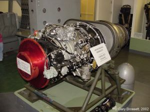
The British Armstrong Siddeley Viper was a turbojet that first ran in 1951, entered service in 1953 and was retired in 2011. It was produced by Armstrong Siddeley, Bristol Siddeley and Rolls-Royce, and was also licensed to Turbomecanica Bucharest and Orao Sarajevo, among others. Based on the Armstrong Siddeley Adder, it was developed as an expendable engine for the Australian Jindivik target drone. Later, with a thrust of about 3,000 lbf, it saw numerous other crewed applications including:
Aermacchi MB-339 & MB-326; BAC Jet Provost & Strikemaster; IAR 99; Soko J-22, G-2 Galeb &
G-4 Super Galeb trainer and light strike aircraft.
The later, heavier Avro Shackletons to boost takeoff and climb performance.
Aero Vodochody L-29 Delfin prototype; Bell X-14; Blue Origin Charon; Dassault M.D.550;
Mystere-Delta; Folland Midge; the Australian Government Aircraft Factories Jindivik target drone;
Handley Page HP.115 and Saunders-Roe SR.53 experimantal/prototype/target drone aircraft.
Hawker Siddeley Dominie and Piaggio PD.808 business jets. [Wiki]
Thanks to Bruce Vander Mark for providing the manual from which this article is based. |
Description
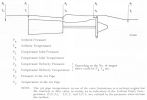 |
| Symbols |
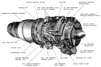
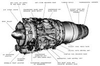
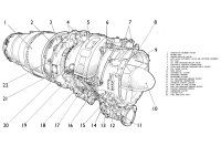
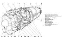
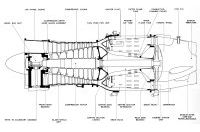
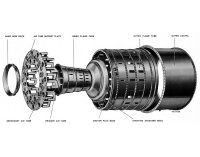
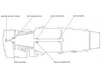
The Armstrong Siddeley Viper turbojet combined an eight-stage axial compressor, an annular combustion chamber and a single stage turbine. The rotating assembly was mounted in three main bearings. The engine fuel system, oil system and accessories were contained in a cooled zone isolated from the hot zone by an external firewall fitted at the compressor/combustion chamber junction.
The
Air Inlet Section comprised a light alloy air intake casing bolted to the compressor casing front and mating with the air intake cowl. The casing served the following purposes:
- Directed air into the compressor.
- Housed the rotating assembly front bearing.
- Housed a central bevel gearbox unit that connected the rotating assembly to an accessory gearbox at the casing base.
- Housed the engine breather system.
- Accommodated the compressor entry guide blade assembly at its rear.
- Provided mounting for two pitot heads, one providing sensing air (P1) for the P1/P2 switch of the compressor control system, the other providing sensing air to the fuel system barometric flow control unit.
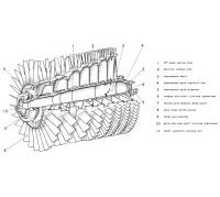
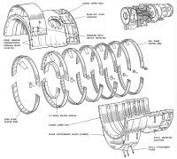
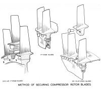
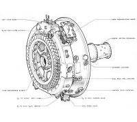
The Compressor Section consisted of a casing and rotor. The compressor casing half sections were bolted together at their axial joint flanges and the stator blades were cemented in carrier ring halves that located in casing grooves. A blade shield unit encircled the casing at the first two compressor stages. An annular chamber in the casing was linked to the compressor fifth stage by a series of radial ports; the outlet from the chamber was controlled by a blow-off valve. The compressor rotor was mounted in the front and center main bearings. The zero and first stage rotor blade roots were of fir-tree form, while the blade roots of the remaining six stages were riveted to the respective discs. The rotating assembly bore formed part of the engine air system. Internal serrations at the front end received a quill shaft that engaged the bevel gearbox unit in the air intake casing while serrations at the rear end were engaged by those of the turbine mainshaft thus transmitting the drive.
The
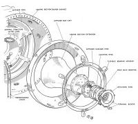
Combustion Section consisted of a center section casing, combustion chamber casing and centrally-mounted inner and outer flame tubes. The center section was bolted to the compressor casing rear and had a rearward extension that served the following purposes:
- Directed compressor air into the combustion chamber through an air flow straightening and eighth-stage stator assembly bolted to the center section front face.
- Housed the rotating assembly center and rear main bearings; the rear bearing was housed in the rearward extension.
- Provided location for starting fuel system primer units, the fuel feed pipes units (burners) of the main system and the igniter plugs together with the engine mounting trunnion housings.
- Incorporated an integral annular chamber that was in direct communication with the compressor delivery air and provided connections to the following:
- Engine anti-icing system
- Compressor control system
- Engine fuel system units
- Aircraft services
A spring-loaded poppet-type drain valve in the casing base carried excess fuel to an overboard drain pipe.
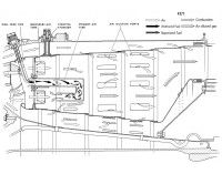
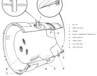
Secured to the center section rear, the combustion chamber casing enclosed the inner and outer flame tubes and provided the mounting for the turbine stator unit and the exhaust cone at its rear. At their front ends, the flame tubes were secured to an air tube support plate incorporating primary and secondary air tubes, the plate being retained within the center section. Deeply-grooved flanges at the flame tube rear ends engaged support rings in the turbine assembly, thus permitting axial tube expansion. A glow-plug installed in the combustion chamber casing lower right side projected into the combustion flame zone.
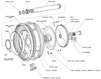
The Turbine Section consisted of a turbine stator unit and a turbine wheel. Bolted between the combustion chamber casing and the exhaust cone, the turbine stator unit had a rearward extension that provided the turbine wheel shroud. The stator inner ring was bolted to a conical support secured to a flange on the center section extension. The turbine chamber forward end was closed by a diaphragm attached to the center section rear and the stator inner ring. A hollow clamp bolt secured the turbine wheel to radial serration at the mainshaft rear end; the shaft was mounted in the rear main bearing and extending forward to engage the compressor rotor.
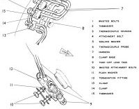
The Exhaust Cone and Propelling nozzle were bolted to the turbine stator ring rear. An inner cone was secured by three radial stay pins that located in inner and outer cone vane housings. The pins were retained by capnuts. A spring-loaded drain valve was housed at the outer casing lower forward end. The turbine shield encircled this location. The exhaust cone had provisions for installing exhaust temperature thermocouples and a power loss pitot.
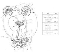
Accessory Drives and Gearbox. All engine accessory drives were housed in the accessory gearbox mounted on the intake casing bottom. A radial drive shaft transmitted power from the bevel gearbox on the air intake casing to the accessory gearbox, which provided mounting and/or drives for the following accessories (looking from the rear).
- Rear face: Left Fuel pump
- Rear face: Right Starter/generator
- Front face: Hydraulic pump
- Left side face: Tachometer generator
- Right side face: Oil pump
The gearbox incorporated oil drain, level and filler plugs, and a connection for the pipe to the oil pressure transmitter.
 |
 |
 |
 |
 |
 |
| Viper 521 |
Viper 522 |
Viper Longitudinal Cross Section |
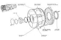
Front Casing |
 |
 |
 |
 |
 |
 |
| Gear Train Diagram |
Compressor Rotor |
Compressor Casing |
Compressor Blades |
Center Section |
|
 |
 |
 |
 |
 |
 |
| Vaporizer System |
Flame Tube Assembly |
Exhaust Cone |
Turbine Assembly |
Thermocouples |
Bearings and Seals |
Fuel System
 |
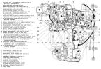 |
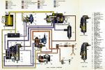
| Viper Fuel System |
The Viper fuel system was an old-school hydro-mechanical device that comprised the following units:
- Low pressure fuel filter, with differential pressure switch and low-pressure warning switch.
- Lucas type fuel pump, incorporating a hydro-mechanical governor.
- Rate reset valve.
- Rate reset isolating valve.
- Barometric flow control unit incorporating an high-pressure fuel cock and a throttle valve.
- Air/fuel ratio control, together with a pressure ration switch.
- Pressure increasing valve.
- Six primer units (starting atomizers)
- Primer solenoid valve.
- Fuel flowmeter.
- Twelve fuel feed pipes.
- Electro pressure control (JPT limiter).
- Synchronizer corrector unit.
The system operated on the flow control principle, in which a controlled pressure difference was maintained across a variable orifice, the area of which was adjusted by the control units to meter fuel flow in accordance with engine requirement. For steady running conditions control was effected either by the barometric flow control unit or the fuel pump governor. During accelerations the rate of flow increase was controlled by the air/fuel ratio control unit.
The Low Pressure Fuel Filter, of the Tecalemit fabric type filter, was housed in a casting located beneath the compressor casing. From the inlet port on the housing, fuel flowed across the filter towards the center, and so to the housing outlet connection. Two switches were located on the housing; the low-pressure switch monitored the outlet pressure, while the other was subjected to the differential pressure across the filter. These switches were electrically connected to warning lamps, and closed when the filter outlet pressure fell to 3.5 psi and/or the pressure drop across the filter exceeded 2.4 psi.
 |
 |
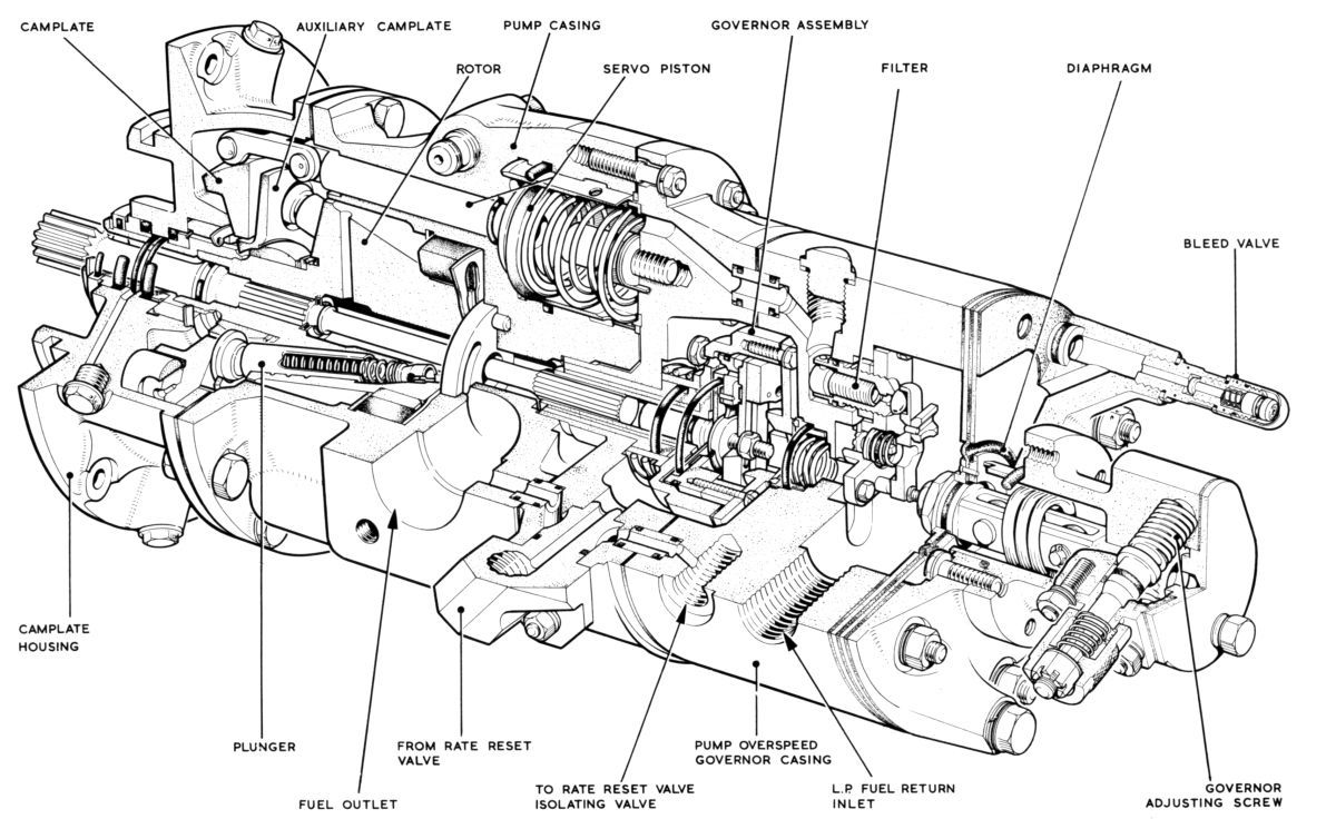
| Fuel Pump |
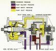
The Fuel Pump, mounted on the gear casing rear face, and consisted of a rotor, supported by a cylindrical carbon bearing, and having formed in it seven inclined cylinders that accommodated hardened steel pumping pistons. The pistons were located by the auxiliary camplate, which was mounted on a universal thrust ball on the pump drive shaft. The pistons ends, which projected from the cylinder bores, butted against a camplate mounted on a trunnion ring and fixed axially by two trunnion pins. The camplate angle could be varied from 90° (zero piston stroke) to 105° (maximum piston stroke). The cylinder bores in the rotor were stepped in diameter with the small ends terminating as ports in the rotor flat face, which engaged on two kidney-shaped ports (inlet and outlet). The rotor was pressed against the port face by seven piston return springs and also by the fuel pressure acting on the annulus formed by the step in each cylinder bore, thus giving a sealing force between the rotor and ports. The camplate angle was controlled by a servo mechanism, which consisted of a piston operating in a cylinder against the action of two springs. The piston was connected to the trunnion ring by a link and piston rod that controlled the camplate angularity, with the springs tending to turn the trunnion ring to the position of maximum angularity (maximum piston stroke). Fuel at pump delivery pressure flowed across one side of the piston, and through a restrictor to the other side, which was connected by passageways to the various half balls in the system. Equilibrium was established when the fuel pressure on one side of the piston equaled the reduced pressure plus the spring on the other side.
The Hydro-Mechanical Overspeed Governor was used to control the engine maximum rpm and depended solely on speed for its operation; governed speed was unaffected by changes in fuel specific gravity. The overspeed governor, contained within the fuel pump unit, comprised a diaphragm that was subjected to governor pressure on one side and pump inlet pressure on the other. The diaphragm was loaded by a spring in tension and carried a button at its center that contacted one end of a pivoted rocker; the other end carried a half ball that controlled the bleed from the spring side of the servo piston. A spring beneath the rocker controlled the system stall pressure. A passageway from the fuel pump outlet was connected via the rate reset valve to the governor rotor chamber, and to the spring side of the governor operating diaphragm.
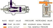
A Rate Reset Valve counteracted pump delivery and servo pressure variations resulting from changes in fuel intake pressure and/or temperature, which in turn affected the governed speed. This valve consisted of a tapered needle acting in an orifice to vary the pressure supplied to the governor operating diaphragm spring side when pump delivery pressure changes occurred. The valve was directly connected to a piston housed in a cylinder against the action of a spring to form a dashpot, which maintained stability when the governor was in control.
The Rotor comprised a shallow cylinder surrounded by fuel at governor pressure on its outside, while its bore was connected to pump suction, the bore being sealed against chamber pressure by a carbon seal and face plate at one end, and by a diaphragm at the other; an orifice in the diaphragm end metered fuel flow from the chamber into the rotor bore at a controlled rate. A weighted lever was connected at one end to the rotor by a leaf hinge and at its other end to the diaphragm center.
Governor Operation. Fuel at pump delivery pressure flowed via the rate reset valve isolating solenoid and rate reset valve to the governor diaphragm chamber, and to the rotor chamber, from where it flowed through a restricting orifice to the rotor bore, which was in communication with the fuel pump inlet. Centrifugal force acting on the weight mass caused the beam to move toward the restricting orifice; the force created due to the pressure difference on the diaphragm opposed this movement so that at an rpm equilibrium was established and the flow through the restrictor was controlled on an rpm basis. As speed increased, this flow was progressively reduced, with a consequent rise in rotor chamber pressure and governor diaphragm chamber pressure, until at maximum rpm the force on the governor diaphragm was sufficient to unseat the half ball, which allowed a bleed from the pump servo piston spring chamber, thus limiting the pump stroke, which in turn limited the fuel supplied to the engine and therefore the engine speed.
 |
| Barometric Flow Control Unit |
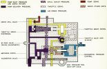
Barometric Flow Control Unit (BFCU)
The BFCU metered fuel flow by introducing a controlled pressure drop across a ported sleeve through which fuel flowed to the engine. The required pressure drop could be obtained by either changing the pump delivery pressure, or by varying the effective orifice area, thus adjusting fuel flow for changes in throttle setting, and/or intake pressure. These separate functions were carried out by the throttle servo unit and the barometric pressure control unit that comprised the flow control unit. The throttle servo unit consisted of a throttle valve surrounded by a ported sleeve that, through a integral pinion, engaged with a rack located on a spindle to which the throttle servo piston was secured. The piston rod maintained contact with a spring which, together with metered fuel pressure, directed a force acting on one side of the throttle servo diaphragm. The diaphragm's other side was subjected to pump delivery pressure and was connected with one end of a pivoted beam. The beam's other end carried a half ball that controlled the flow through an orifice that was connected with the fuel pump servo. The forces acting on the diaphragm were equal when pump delivery pressure on one side equaled metered pressure plus the spring force on the other.
Throttle Servo Operation. If the throttle valve was moved to increase rpm, fuel at pump delivery pressure was directed to the throttle servo piston underside causing it to move toward the spring, thus increasing the force on the diaphragm spring side, causing the half ball to move nearer to its seat. During this period the rack drove the pinion to follow up and reposition the sleeve around the throttle valve, thereby cutting off the servo piston supply. When the flow through the half ball valve was reduced, the pump servo moved to increase its stroke, thereby increasing the fuel flow until pump delivery pressure acting on the area opposing the spring, providing an equal and opposite force so that flow through the control orifice was restored to the amount required to maintain fuel pump servo equilibrium at the new condition. Closing the throttle reversed the sequence, commencing with fuel being directed by the throttle valve to the servo piston top. Whichever side of the servo was connected with fuel under pressure, the other was connected with the pump inlet via a secondary passage through the throttle valve. The barometric pressure control comprised an exhausted capsule housed in a chamber vented to intake pressure. A needle valve connected to the top of the capsule operated to restrict fuel flow through the a servo piston bore and together with a fixed restrictor this formed a potentiometer. Pressure tapped off between the potentiometer restrictors was routed to a metering piston underside, which was spring loaded on the opposite side.
Barometric Pressure Control Operation. A reduced pressure applied to the capsule caused it to expand, and in so doing caused the needle valve to restrict the flow back to the pump inlet, increasing the pressure between the potentiometer restrictors. This pressure increase caused the metering servo piston to move against its spring, and reduce the size of the metering orifice. The resultant decrease in metered fuel pressure reduced the pressure on the throttle servo diaphragm spring side, which then moved to increase the pump servo half ball opening, so reducing pump delivery pressure until equilibrium was established across the diaphragm. Metering servo piston movement continued until the reducing potentiometer pressure acting on the metering servo piston provided a force equal and opposite to the spring force. A spring-loaded augmenter valve fitted to the unit inlet was closed at idling conditions, directing the engine fuel supply through an adjustable by-pass valve. This valve metered the idling fuel flow, establishing equilibrium of the throttle servo diaphragm at a suitably reduced pump delivery pressure to meet the engine requirements. The high-pressure cock located in the outlet port interrupted the fuel flow when stopping the engine. When in the open position it permitted the passage of fuel to the air/fuel ratio control; when in the closed position it returned fuel to the pump inlet.
 |
| Air/Fuel Ratio Controller |
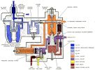
Air/Fuel Ratio Control (AFRC)
The AFRC limited the engine fuel supply during acceleration so that an increase in engine speed was obtained without incurring high turbine entry temperatures and without compressor surge. The AFRC functioned on the principle that if the air/fuel ratio was maintained within certain limits the combustion temperature was also controlled; the AFRC took compressor pressure and metered fuel pressure as measures of air and fuel flow. The AFRC comprised a cast body subdivided into a capsule chamber and a metering chamber by a pivot plate assembly, carrying a rocker lever that extended into both chambers. The beam portion extending into the metering chamber was secured to the casing by a spring. Another spring secured the combined metering piston and plunger to the beam. Fuel at metered pressure was delivered to the smaller piston area, and a further supply of metered fuel was delivered via a restriction to the chamber beneath the piston crown, which communicated via a half ball with the AFRC outlet. This arrangement provided a servo system for positioning the metering plunger in its orifice. At steady running conditions the half ball valve connected to the beam controlled the flow from piston crown to adjust the pressure to that required to maintain piston equilibrium so the metering plunger was correctly positioned. The pressure drop across the metering plunger was felt on the acceleration rate adjuster piston, which featured a rocker with a half ball that controlled flow from the fuel pump servo and in so doing controlled the rate at which the fuel supply from the pump was increased during acceleration. The pressure on the piston low pressure side was supplemented by a spring with an adjuster to alter its spring force to suit engine requirements during acceleration. The beam's other end was connected to an exhausted capsule secured to the casing. The pressure in the capsule chamber was taken from the compressor delivery via a pressure ratio switch.
AFRC Operation. During steady running conditions the metering servo half ball was unseated, so as to maintain correct metering plunger positioning in its orifice. During acceleration, the fuel flow increase also increased pressure across this orifice. This pressure difference was felt across the rate limiter piston, causing it to move when the limiting pressure difference was reached and open the half ball controlling the fuel pump servo piston. This had a limiting effect on fuel delivery from the pump, so that the rate of over-fuelling to the engine was controlled, to give the minimum acceleration time without incurring a compressor stall. The controlled fuel flow increase caused the engine to accelerate, and in so doing increased the compressor delivery pressure, which was routed via the pressure ratio switch to the control capsule chamber. This caused the capsule to contract, which moved the beam to further open the metering servo half ball, increasing the bleed from the metering servo piston underside, moving the metering plunger to increase the metering orifice area, which decreased the pressure difference across the orifice. This decrease applied to the rate limiter piston caused the half ball to close, which permitted a further increase in fuel flow from the pump so that acceleration was continued. If the compressor surged its delivery pressure did not increase at the normal rate during acceleration, this scheme protected the engine by preventing further fuel flow increase.
The Pressure Ratio Switch operated in conjunction with the AFRC to impart a step in the operating line, thus ensuring that the AFRC retained its functioned as an acceleration control, without limiting engine performance at altitude. The switch comprised a chamber that housed two capsules in tandem that actuated a valve. One capsule's interior was connected to intake pressure while the other capsule was exhausted; two passageways were connected to compressor delivery pressure at their outer ends and to the engine bay via the bore of the large capsule at their inner ends. Each passage contained two restrictors with the space between the restrictors connected to the AFRC and switch unit capsule chamber respectively. When the engine was running at low speed the valve was open and the compressor delivery pressure air supply flowed through the passageways, with a consequent pressure drop. This reduced pressure was applied from one of the passageways to the AFRC and from the other to the unit capsule chamber. As engine speed increased the capsule chamber pressure rose to a value that closed the valve. When this happened the flow in the passageway connected to the AFRC ceased so that full delivery pressure was applied to the capsule, shifting the operating line.
 |
|
The Pressure Increasing Valve consisted of a spring-loaded slotted valve operating in a ported sleeve. The piston was pre-set to open at approximately 80 psi and thus controlled the pressure at which fuel was passed to the starting atomizers and main burners; it also ensured sufficient fuel system back pressure for efficient servo operation. During the initial starting operation the fuel pressure was insufficient to overcome the valve spring strength and fuel was fed to the starting atomizers through the starting solenoid valve. When light up occurred the engine speed increased progressively and a corresponding fuel pressure increase was exerted on the valve face. When sufficient pressure was attained the valve was depressed to expose the valve sleeve ports and fuel was allowed to pass to the burners.
The Starting Fuel Solenoid Valve was energized during the starting cycle for 23 sec to fill the six starting atomizers that initiated engine light up. The conical valve was brought to the open position by an energized solenoid, and returned to the closed position by a spring.
Fuel System Operation
Fuel system manual control was effected via the throttle lever and the high-pressure shut off cock levers in the flight compartment. When the high-pressure shut off cock was in the open position, throttle lever movement selected a basic fuel metering setting and thereafter the fuel flow was adjusted automatically to suit prevailing conditions. All such fuel flow adjustments were effected by the BFCU and AFRC through the fuel pump servo system.
Indicators
- Fuel filter obstruction was detected by a Smith differential pressure switch that drove a magnetic indicator in the aircraft flight compartment. The switch was mounted on a bracket on the fuel filter side; two flexible pipes conveyed pressure supplies from both the high and low pressure sides of the filter element.
- Low fuel pressure was detected by a Smiths low pressure warning switch was mounted on the fuel pump outer elbow; the switch drove a magnetic indicator in the aircraft flight compartment.
- Fuel flow rate was detected by a Meterflow flowmeter installed in the pipe line from the pressure increasing valve to the fuel manifold, and drove a gauge in the aircraft flight compartment.
- The Jet Pipe Temperature (JPT) Limiter held the JPT to a predetermined value by reducing the fuel flow when high temperatures were detected. This control was electrically operated. Five K.L.G. Siamese type thermocouples located in the exhaust cone jointly drove the pilot's JPT indicator gauge and the Ultra temperature control unit. If the thermocouple electromotive force exceed the reference electromotive force in the temperature control unit, the resulting error signal was amplified and actuated a valve that controlled the amount of fuel spilled from the BFCU diaphragm underside. This increased the pressure drop across the diaphragm, reduced the fuel pump stroke, which reduced fuel flow and lowered the JPT. This control had Takeoff and Climb settings; the pilot selected accordingly. However, if the system was malfunctioning it could be isolated by selecting Off.
Engine Synchronization. A Dowty-Rotol synchronizer allowed the pilot to synchronize two engine rpm's with ease and accuracy. A tacho-alternator provided the signal for cockpit rpm indications and a signal to a corrector motor, which in turn operated a fuel system spill valve in the slave engine only. This increased fuel pump output (thus increasing the slave engine's rpm) until slave and master rpms were synchronized.
Control Conditions Steady Running
For any steady running condition at intermediate throttle settings fuel flow was be metered by the BFCU. Variations in flow requirement with variations in P1 were compensated for by the action of the capsule, but repositioning of the throttle was necessary to correct for changes in T1.
- During slam accelerations fuel flow control was achieved by the air/fuel ratio control unit.
- At maximum rpm the fuel pump governor controlled engine fuel flow.
- When JPT reached the selected high limit the JPT Limiter controlled engine fuel flow by restricting it to a value less than that required for maximum rpm.
 |
| Thrust Limiter/Servo Amplifier Unit |
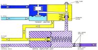
The Automatic Thrust Limiter operated at temperatures of ≤ -4°C when the engine thrust would otherwise exceed that required; it trimmed the engine's fuel flow in terms of pressure ratio (P2/P1) to a given thrust value. The ratio P1 total and P2 static pressure was measured across a diaphragm in the thrust limiter that was loaded against an evacuated capsule and linked by a lever to a half ball valve. The P2 signal increased with engine speed until the required pressure ratio was reached, at which point the diaphragm deflected, causing a spill from the half ball valve. This spillage caused a pressure loss, which was fed from pump delivery via two series restrictors on the diaphragm spring side in the amplifier. The diaphragm's other side was subjected to BFCU internal servo pressure. The pressure loss on the spring side eventually caused the diaphragm to deflect and spill BFCU internal servo pressure to pump inlet via a plate valve. With the reduction of BFCU internal servo pressure, the pressure difference across the BFCU throttle diaphragm increased, which via the BFCU half ball valve reduced the fuel pump output, thus limiting engine thrust.
Lubrication System
 |
 |
 |
 |
| Lubrication System Plumbing and Oil Tank |
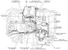
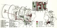
The lubrication system was self-contained within the engine. There was no oil cooler or oil cock. The pressure system comprised two distinct circuits: The main pressure circuit, supplied by the main oil pump, served the engine front portion; the metered circuit, which served the center and rear main bearings. The metered circuit was a total loss scheme that was supplied by two micro-pumps, one for each bearing. The oil scavenge system operated on the dry sump principle.
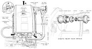
The Oil Tank was mounted on the compressor blade shield right side by three anti-vibration mounting brackets. The filler cap incorporated a dipstick. An oil temperature thermometer bulb was fitted in the tank rear face, and the breather outlet was equipped with a Hymatic pressure relief valve.
The Oil Pump was mounted on the accessory gearbox at the air intake casing base. The main oil pump employed separate gear-type pressure and scavenge pumps. An intermediate gear transferred the drive from the scavenge pump to the pressure pump and had a integral cam that provided micro pump drive. A poppet static sealing valve fitted adjacent to the pressure pump outlet closed the pump delivery port when the engine was stationary, thereby preventing oil seepage into the engine. The plunger-type oil pressure relief valve was not adjustable.
Both Micro Pumps were mounted on the oil pump cover. Each micro pump consisted of a spring-loaded pumping piston and a metering piston. Movement was transmitted to the pumping piston by a plunger that was held in contact with the operating cam by the piston spring. The opposing metering piston was also spring-loaded and operated by the pumping piston through the medium of the oil drawn into the pump. The pumping piston delivery stroke caused the metering piston to uncover the delivery port. The adjustable metering piston spring allowed the oil amount discharged to be changed.
Oil Filters. The lubrication system incorporates a non-removable screen in the oil tank base through which oil flowing to the oil pump outlet connection passed. The pressure, scavenge and micro pump filters were all housed in the pump unit; the first two were of the gauze type, but the micro pump filter had a replaceable felt element.
A Hymatic Relief Valve interposed between the breather pipe and its oil tank connection maintained a 3 psi oil tank pressure, which ensured positive oil delivery to the pump at all altitudes. The spring-loaded thimble valve carried a valve rubber that sealed on a metal seating. The valve was rig set. Gauze disc filters were incorporated in the inlet and outlet connections.
Oil Pipelines of rigid steel were employed throughout the lubrication with the single exception of a flexible pipe from the accessory gearbox connection to the oil pressure transmitter.
Priming and Drain Points were located on the main oil pump and accessory gearbox in the following positions:
- Micro pump banjo connections.
- Pressure oil filter.
- Filler plug on the AC generator drive adapter.
Lubrication system drain points were located in the following positions:
- Oil tank.
- Pressure oil filter.
- Scavenge oil filter.
- Accessory gearbox rear face.
Pressure System Operation
Oil discharged from the pump lifted the static sealing valve and entered the pressure oil filter. On leaving the filter, the oil entered a duct (communicating with the pressure relief valve) with two branch ducts; one supplied the micro pumps and the other served the air intake casing, lubricating the front main bearing, bevel box unit, the accessory gearbox gears and their bearings. When the delivery oil pressure was normal the relief valve was opened sufficiently to uncover a portion of a port through which oil was bled to lubricate the pump-driven intermediate gear, driving pinion and transfer pinion before draining into the accessory gearbox. If delivery pressure rose above normal the port was fully exposed and bypassed the excess oil back into the accessory gearbox. Pressure oil to the low pressure warning switch was ducted from the pressure filter outlet through the intermediate gear and pump cover to the switch.
Metered System Operation
Pressure oil from the oil pump flowed through the micro filter to each micro pump inlet port and entered the micro pump cylinder when the pumping piston was at its lowest position. As the cam revolved the pumping piston moved outward, covering the inlet port. The two pistons then moved together with a metered quantity of oil between them. Towards the end of the pump stroke the metering piston uncovered the outlet port; continued pumping piston movement evacuated the oil from the cylinder. The metered oil quantity was then supplied to the bearing and finally passed into the exhaust gas efflux. As the cam revolved further, the pistons moved inwards together until the metering piston covered the outlet port and was held stationary. The pumping piston, however, continued its inward movement and uncovered the inlet port to recharge the cylinder with pressure oil.
Drain and Scavenge System
Drain oil from the front main hearing and bevel box unit flowed into the accessory gearbox and was then drawn through the scavenge filter to the scavenge pump, which returns it to the oil tank.
Later engines were modified with a "squeeze film" front bearing, which gave a cushioning effect to dampen shaft and thrust hearing flexing, reducing vibration. The squeeze film was achieved by tapping oil from the front bearing feed to an annular oil well in the housing that occupied a radial clearance between the bearing and housing.
Oil tank pressure was limited by a Hymatic relief valve that blew off at a predetermined pressure. The valve was linked to the intake casing, which was vented through the engine overboard breather pipe.
Indicators
Oil Pressure. A Sangamo-Vtesron oil pressure transmitter drove a ratiometer type pressure gauge on the flight deck. The transmitter was mounted to the engine air intake casing right side and received its pressure supply through a flexible pipe coupled to the air intake casing oil supply duct.
Low Oil Pressure. A Smiths low pressure warning switch mounted on the oil pump serves a low-pressure warning light on the flight deck.
Oil Temperature. A Sangamo-Weston thermometer bulb in the oil tank was connected to a ratiometer type temperature gauge on the flight deck.
Air System
 |
| Air System |
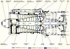
Since burning fuel resulted in high gas temperature a proportion of the air flow was directed to hot engine components in order to keep them at safe working temperatures. Air was also tapped off to pressurize the front bearing labyrinth seal, and the heating and pressurization of various aircraft services.
Front Bearing Pressurization. To prevent compressor suction from depriving the front main bearing of lubricating oil, some air from the 6th compressor stage entered the compressor discs where some of it traveled forward to pressurize the space between the oil seal and the labyrinth seal to the rear of the bearing.
Turbine Disc. The 6th stage air also flowed aft through the hollow mainshaft and a drilling in the turbine clamp-bolt, and passed across and cooled the turbine disc rear face. The turbine disc front face was cooled by 7th stage compressor air, which reached the face by flowing through drillings in the center section diaphragm to an annular space between the mainshaft and combustion chamber inner casing, and then through further drillings in the rear bearing support and the rear diaphragm. In both cases, after cooling the turbine, the air joined the exhaust stream at the turbine blades.
Center and Rear Bearings. Some 8th stage compressor air pressurized the center bearing labyrinth seal; air leakage through the seal scavenged the bearing oil. This air flowed aft through the center section extension to pressurize the rear main bearing and to cool the turbine wheel front face before being discharged into the main exhaust stream. A portion of the air passed through holes in the center section extension to cool the rear conical support and rear diaphragm before passing a series of holes in the inner blade support ring and slots in the rear diaphragm. This air joined cooling air from the turbine wheel front face and discharged into the main exhaust stream.
Aircraft Services. Six connections on the center section allowed air to be tapped off for various aircraft services. This air was used as follows:
- Cabin pressurization and conditioning.
- P2 supply to the P1/P2 switch.
- P2 supply to the air/fuel ratio control.
- P2 supply for anti-icing the AERC pressure ratio switch.
- P2 for anti-icing P1 pitots.
- Engine anti-icing.
- P2 supply for the thrust limiter.
Air Bleed Valve
 |
 |
 |
 |
Compressor
Bleed Valve |
Bleed Valve
Operating Limits |
Blow-Off Valve |
Air Bleed Valve |
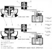
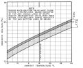
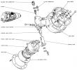
An air bleed valve (Blow-Off Valve) prevented compressor stall when running at low engine speed. Under these conditions the air bleed valve was open and provided a bleed to atmosphere, which in turn controlled the axial velocity of the air entering the compressor to adjust the angle of attack at the compressor inlet. As the engine speed increased a control system closed the air bleed. The compressor pressure ratio for a given rpm varied with intake temperature; a temperature reduction increased the pressure ratio and vice versa. The air bleed was designed to close at a constant pressure ratio; the rpm at which it closed varied with temperature. This could result in the air bleed being open at sea level but would close at some rpm value less than idling at altitude. To counteract this effect a pressure ratio switch functioned automatically to provide a variable setting.
The pressure ratio switch was similar to the one found in the fuel system. It operated at a variable pressure ratio that rose from approximately 2.2:1 at sea level to 3.9:1 at 40,000 ft. This was effected by introducing a bias into the unit that required an increased effort to close the switch plate valve. At sea level the amount of increase in capsule chamber pressure required to overcome this bias was small in relation to the pressure as a whole. At altitude the chamber pressure increase required to overcome the bias represented an increased chamber pressure percentage as whole. Thus an increased pressure ratio was necessary to close the switch plate valve. A pressure ratio switch solenoid valve was connected to the pressure ratio switch but was not essential for the normal bleed valve operation. This switch, along with its operating details were described in the anti-icing section.
The control valve unit was integral with the blow-off valve and connected to the pressure ratio switch in a housing that contained a two-position piston type valve that directed air as required for air bleed valve operation. Air for operating this control valve was taken from the compressor delivery to one side of the valve and via the pressure ratio switch to the other side. The valve opened or closed an atmospheric vent as required. The air bleed unit was bolted to the compressor casing upper left side and connected with a port from the 4th compressor stage. The unit had a centrally-located housing for a piston sleeve in which an actuating piston for the air bleed valve was located. A passageway at the piston housing top connected the air passage from the control valve via a restrictor to the piston top; the restrictor imparted a steady piston movement. A further housing surrounding the cylinder unit incorporated the bleed valve seating and provided an annular orifice through which air escaped when the valve was open. A gauze screen prevented foreign matter ingestion.
Low rpm Operation. At I.S.A. standard conditions, when operating at less than 73-75% rpm, the pressure ratio switch plate valve was unseated, thus maintaining an air flow to atmosphere so that air at KP2 provided the operating force on the control valve plunger larger area. This was opposed by P2 on the smaller area, which caused the valve to position itself so as to vent the air bleed valve piston top to atmosphere. Under these conditions air from the 4th compressor stage was applied to the air bleed valve piston inside area, which provided sufficient force to keep the blow-off valve open.
Increasing rpm. As engine speed increased above 75% at I.S.A. conditions, the resultant increase in pressure ratio caused the pressure ratio switch plate valve to close, stopping flow to the atmosphere and causing the pressure applied to the control valve plunger large area to rise to P2. The control valve plunger repositioned and closed the atmosphere vent. Simultaneously the air bleed valve piston top was connected with an air supply from the compressor delivery, which provided sufficient force to close the valve.
Anti-Icing System
 |
 |
 |
| Air Intake Anti-Icing |
Anti-Icing
Continuous
Operation
Limitations |
Butterfly Valve Details |
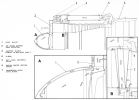
Engine anti-icing was accomplished by P2 air to the Engine Intake Guide Vanes and the top two intake strut leading edges.
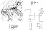
Nose Fairing. Air from the center section casing was fed via an air control valve (Teddington) to an annular space surrounding the air intake casing. Each entry guide vane blade was hollow, thus permitting the warm P2 air to flow through it, and finally exhaust back to the compressor inlet. Similarly P2 air passed between the hollow struts and the three aerofoil extensions. thus preventing ice build up on their leading edges. Through suitably aligned ports the nose bullet leading edge was supplied with P2 air that again exhausted into the compressor P1 stream. The Teddington two position icing control valve, which consisted of 2.5" diameter butterfly valve, was controlled by a electrically driven actuator. Anti-icing was selected by a three position switch that permitted selection of "Anti-icing ON above 92%; "Anti-icing ON" and "Anti-icing OFF". The butterfly valve position was indicated by two magnetic indicators that showed OPEN or CLOSED or CROSS-HATCHED for the mid-position, and when the system was not energized. When atmospheric conditions necessitated anti-icing protection the pilot moved the anti-icing selection switch to "Anti-Icing ON" if rpm was below 92%; the pilot also moved the relight switch to "ON". If the engine was operating at or above 92% the pilot selected "Anti-Icing ON above 92%", immediately decelerated the engine to below 92%, and then moved the switch to "Anti-Icing ON".
Bleed Valve Operation in Conjunction with the Anti-Icing System
 |
 |
Bleed Valve / Anti-Icing
Operation, Limitations |
To prevent possible surge in icing conditions the air bleed valve functioned in conjunction with the anti-icing system so that the bleed was open when the altitude was above 15,000 ft with the anti-icing switch selected "Anti-icing ON". In addition to the components described for normal compressor bleed operation, an aircraft-mounted barometric switch and a pressure ratio switch solenoid valve were necessary to integrate bleed valve operation with the anti-icing system.
The barometric switch had an evacuated capsule housed in a chamber that was vented to atmosphere. At an atmospheric pressure corresponding to 15,000 ft expansion of the capsule was sufficient to close a contact pair, which armed the circuit to the pressure ratio switch solenoid valve. This two-position valve controlled the pressure ratio switch capsule chamber pressure and remained in the closed position for all normal bleed valve operating conditions, but moved to the open position when anti-icing was witched to "Anti-icing ON" at altitudes above 15,000 ft. With the barometric switch closed and "Anti-icing ON" selected the solenoid became energized to open the valve. This allowed the capsule chamber of the pressure ratio switch to become vented to atmosphere, thus the switch plate valve was unseated so that KP2 was delivered to the control valve plunger larger area, resulting in the air bleed valve in the open position as previously described. With "Anti-icing Above 92%" selected air bleed valve control was effected in the normal manner.
Starting System
 |
 |
| Starting System, Busbar Connections |
The Viper employed an electrical starting system that rotated the engine by a combined starter/generator, which was an aircraft installation item. Starting was normally conducted with an external power supply. but the aircraft batteries could be employed if necessary. The starter/generator rotated the engine via a gear train and drive shaft in the accessory gearbox and air intake casing. Starting was initiated through an engine start selector switch and a starting switch in the flight compartment. Thereafter the starting cycle was controlled automatically by a time delay unit that determined the point in the cycle at which the circuits to the high energy ignition units and fuel system primer solenoid were completed to initiate combustion. Power supplies to these circuits were cancelled automatically by an overspeed relay that operated when the starter/generator load was relieved after engine light-up. The starting sequence could, however, be terminated at any time by tripping the starting circuit breaker.
Prior to starting, the No.3 battery was supplying a positive potential to the engine selector switch. When the No.1 position on the engine selector switch was selected the "start selected" warning light (green) illuminated and the start switch was armed. When the start switch was operated to "START" the starter/generator contactor coil was energized via the closed contacts of the field contactor, which closed the start contacts and completed the circuit to the starter motor through the overspeed relay coil. The time delay operating coil was also energized, thus illuminating the starter operating warning lamp, and supplying the Time Delay Unit. After two seconds the Time Delay Unit contacts closed and caused the component relay to become energized. This energized the priming solenoid to allow fuel to the starting atomizers and energized the high energy igniter units. When the starter switch was released the field changeover relay coil remained energized by current from the engine selector switch, the Time Delay Unit, and the closed contacts of the overspeed relay.
The Time Delay Unit contacts opened 25 seconds after the starter switch was initially operated, causing the component's relay to deenergize, which subsequently deenergized the field changeover relay and starter contactor. With no current to the starter motor, the overspeed relay also was deenergized, terminating the cycle. The engine typically lit up during the cycle and its acceleration eventually caused the starter to speed up, which generated a back emf that reduced the current through the overspeed relay coil. Eventually the current was no longer sufficient to hold the overspeed relay energized. When this occurred the field changeover relay and starter contactor were deenergized, preventing the motor from reaching excessively high rpm when offloaded.
When the relight switch was operated, the component's relay was energized and the igniters and fuel primers operated. At the same time the starter operating warning light illuminated, indicating that a supply was available. The starter, however, did not operate. The pilot was required to operate the starter switch and switch off relight when the generator came on line.
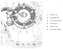
High energy igniter plugs were mounted in the engine center section casing at the 5 and 7 o'clock positions and adjacent to two of the six fuel system primer units. Each igniter plug was served by a individual high energy ignition unit mounted in the aircraft rear fuselage The igniter cable connector featured a right angled terminal housing in each plug body. Each plug's central electrode was carried in, but insulated from, an outer sleeve that formed the earth electrode. A pellet of semi-conducting material was inserted between the electrode ends and formed a discharge path. The High Energy Ignition Units delivered a very high energy electrical discharge; a shock from one would be fatal. Before starting work on or near a unit the low tension supply to the unit was to be isolated in an approved fashion and a one minute wait initiated before beginning work.
Operation. When the circuit to the high energy ignition unit was completed a small electrical leakage from the unit passed to earth across the igniter plug pellet and heated the semi-conducting surface. Due to the negative temperature/resistance characteristics of the pellet, a low resistance path was created and the energy stored in the high energy ignition unit discharged across the ignited plug electrodes in the form of a high intensity spark. This discharge occurred at about twice per second and promoteds combustion of the air/fuel mixture.


