|
|
 |
 |
|
|
|
|
|
|
Early Experiences of a Gas Turbine Engineer
by Clayton Huben
After discharge from the Air Force in 1949, I enrolled at Purdue in Aeronautical Engineering. I chose this school because at that time the aeronautics department offered three major fields of study: aerodynamics, structures and power plants. The professor in charge of the power plant option was known as Piston Joe Liston and he had a wealth of knowledge and stories related to engine development in the 30s and 40s. The school was located at the airport so there were no problems running engines both indoors and out. The school had been given two Westinghouse turbojet engines, a model 19 and a model 9.5 which were installed in test cells and briefly demonstrated by the staff.
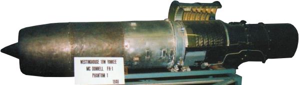 |
| The Westinghouse Model 19 |
For the students to gain experience with turbine engines, the school used GE turbochargers. One of the professors designed a single can burner that was installed between the compressor outlet and the turbine inlet . Using compressed air impingement, the rotor would be spun up, the burner lit and by carefully modulating the fuel valve, it was possible to make it self-sustaining. Most times however, when the impingement air was turned off, the RPM would begin to decrease and the turbine inlet temperature increase and would necessitate a shut down and retry. Hesitation or a less than delicate use of the fuel valve would result in torching the turbine blades off. Once self sustaining speed was achieved, we would take enough data to calculate the efficiency of the different components.
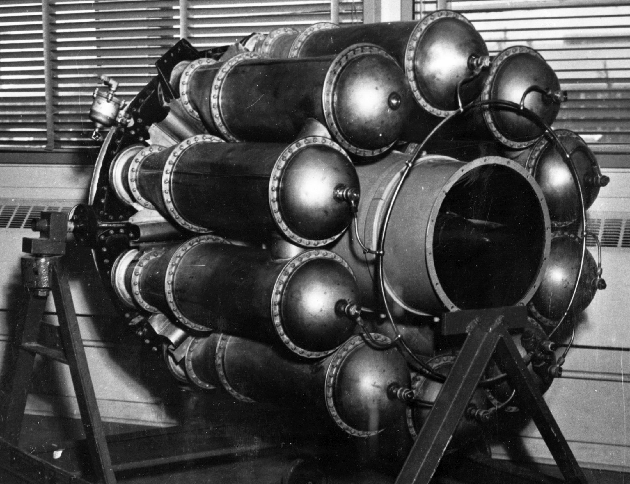 |
| General Electric I-16 Jet Engine |
The University had been given a number of airplanes after the war and one was a P-59 with two GE I-16 Whittle type turbojet engines. As sort of a treat, we seniors got to run up one of these engines in the airplane.
Although the curriculum I selected required attending class during the first two summers, I was free during the summer between my junior and senior year and was fortunate enough to obtain an apprenticeship at Pratt & Whitney. I was assigned as a junior technician to a crew chief who ran one of the altitude test cells in the Willgoos Laboratory. This was an advanced facility for its time and our task was to determine the altitude performance of the T34 turboprop engine. I believe the engine had a sea level performance of about 3,500 horsepower at that time. One evening everything was running smoothly when suddenly the dynamometer began driving the engine instead of absorbing its output and we found that we had lost all of the turbine blades. In another test cell, the afterburner was being developed for the J48. When they had a hot test, all of us technicians would be called to their control room. At that time all data was recorded by hand on data sheets. We would each be assigned a bank of ten manometers and when the test engineer shouted read, we would each record our assigned readings as fast as we could.
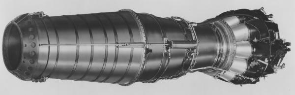 |
| Pratt & Whitney J48 with Afterburner |
The J57 was also being developed, and although we weren’t allowed to see the engine or any of the test results, we did hear the rumor that the pressure ratio was more than 12:1 which was unbelievable to us since it was twice that of our T34. This summer job was great except for one drawback. When the laboratory was constructed large diameter valves were not available, and each duct (I believe they were 60 inches in diameter) had a blanking plate that could be mounted parallel to the flow or perpendicular to the flow to direct the air to the individual test cells. As soon as one test was over, we summer interns would need to open a manhole in the ducting and reposition the blanking plates. This was a hot, wet and smelly task.
 |
| Experimental Pratt & Whitney XJ57-P-1 |
After graduation, I went to work for Continental Aviation & Engineering in Detroit, Michigan. Carl Bachle, who was the vice-president of engineering, had negotiated a license from Turbomeca in France for their small turbojet and turboshaft engines. This was an opportunity to begin a career in gas turbines in a much smaller company than Pratt & Whitney. On my first day, I was assigned some tasks in the engine assembly area. Having never worked in a serious union environment before, I had two violations cited against me by the union before noon. My boss decided that I should become an analytical engineer instead of a test engineer and I began working on the Americanization of the French Marbore turbojet which became the Air Force J69.
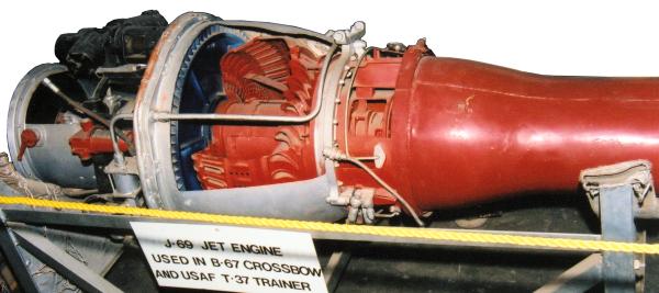 |
| Continental J69 Cutaway |
Cessna Aircraft Company had won a contract to develop the T-37 trainer using the J69 turbojet. Around the same time, Ryan Aircraft Company also decided to use an uprated version of the engine in their Firebee target. To expedite both programs, early flying was done with French engines suitably modified by Continental; the Air Force further decided to modify an F-94 to make a flying test bed for the engine. Lockheed Aircraft Services modified the aircraft by removing the radar in the nose and installing an instrument bay and mounting a pod beneath the fuselage to house the Continental engine. The controls for the Continental engine and the instrumentation were installed in the rear cockpit. When the scheduled flight test engineer declined because he was recently married, I quickly volunteered and was given the job. The airplane was kept at the Wright Patterson Air Base and was flown by pilots from the fighter test section. For Cessna to begin flying the prototype T-37, the French engine needed to pass a 50 hour Preliminary Flight Rating Test. This test was being run by the Air Force on one of their open air test stands. Although the engine was essentially an unmodified Marbore, it did have a different fuel control that was adapted by Continental. One morning I was awakened at my motel by an urgent call from the officer responsible for the test. I rushed to the Base and found the engine running merrily at idle but it would not accelerate. After considerable discussion with the officials I convinced them that the engine would receive many more shocks and bumps in the airplane than on the test stand and thus I should be allowed to simulate this. They finally agreed that I could give the control one strike with a rubber hammer. I went up to the engine knowing the orientation of the metering valve and gave it a solid blow. I was rewarded by an immediate acceleration of the engine. The problem did not reoccur during the remainder of the test or during any of the aircraft flights. I’m sure the Air Force wanted the engine to pass the test as much as I did.
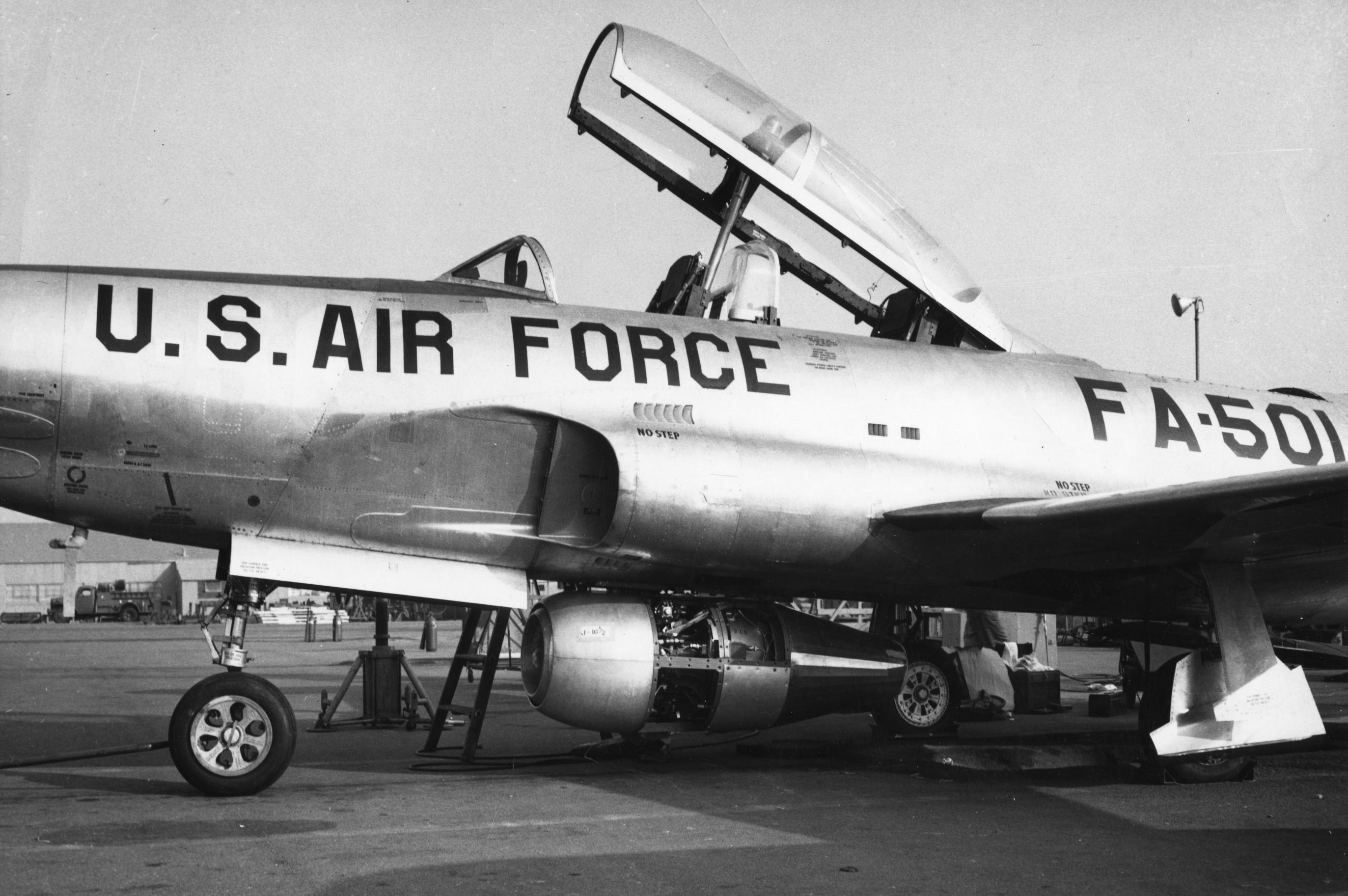 |
| Lockheed F-94 with J69 in Pod Beneath Fuselage |
The testing of the engine for the Cessna trainer application was mainly concerned with evaluating different fuel schedules for acceleration and deceleration at altitudes up to 35,000 feet, although some time was devoted to determining the air start capability. The program on the target engine was more exciting. One of the applications for the target required starting at 40,000 feet. The system we finally developed utilized two pyrotechnic igniters and a lead slug of special fuel. A two gallon tank was placed in series with the normal fuel supply and filled with normal propyl nitrate. No one paid any particular attention to the hazards this fuel represented and I would usually have a 5-gallon can in the trunk of my car. We would spend 30 to 40 minutes climbing to 40,000 feet, the pilot would set up a stabilized Mach number, and I would open the inlet doors to the engine, start the instruments and then punch the start button. A few seconds later a large plume of flame would follow us and the engine would begin to accelerate. It would somewhat overshoot the throttle setting due to residual fuel in the combustor, then it would settle down to an RPM somewhat above idle. At this point the governor valve would be wide open because the heating value of the propyl nitrate was only about half that of JP-4. Then the JP-4 would arrive and the engine would again accelerate like a scalded cat. Once the engine was stabilized at 100 percent RPM, I would shut it down and we would begin a slow decent to the field. The data acquisition system used in those days consisted of a panel of "steam gages" that was photographed by a 16 mm movie camera and a recording oscillograph that had 16 channels for high response recording. At that time the Air Force had a contract with the University of Dayton that provided students a part time job reading the film frame by frame and recording all of the gage values. They also measured the deflection of each oscillograph trace , converted it to engineering units and synchronized the time with the photo panel. Upon landing, I would rush my data to the university, and with luck have the results within a few days.
Since I was Continental’s one man flight test department, I also got to fly in the T-37 at Cessna. One of the tests I was involved with concerned measuring the distortion pattern at the engine inlet. We installed a matrix of total pressure probes at the face of the engine inlet and flew a number of flights covering different incident and yaw angles. I took all this data back to Detroit and plotted the different total pressure profiles. At that time Continental had an engineering consultant named Homer Wood who spent one week each month with us in Detroit. I proudly showed him these profiles which I thought were quite good and he sort of agreed, however he suggested that I calculate the velocity at each point and plot them. Much to my chagrin, there were areas where the velocity was essentially zero or perhaps even negative. I did redeem myself however when I redesigned the cooling duct to the starter-generator which had been overheating. I saw a T-37 that was flown to the EAA convention a couple of years ago and it still incorporated my cooling duct.
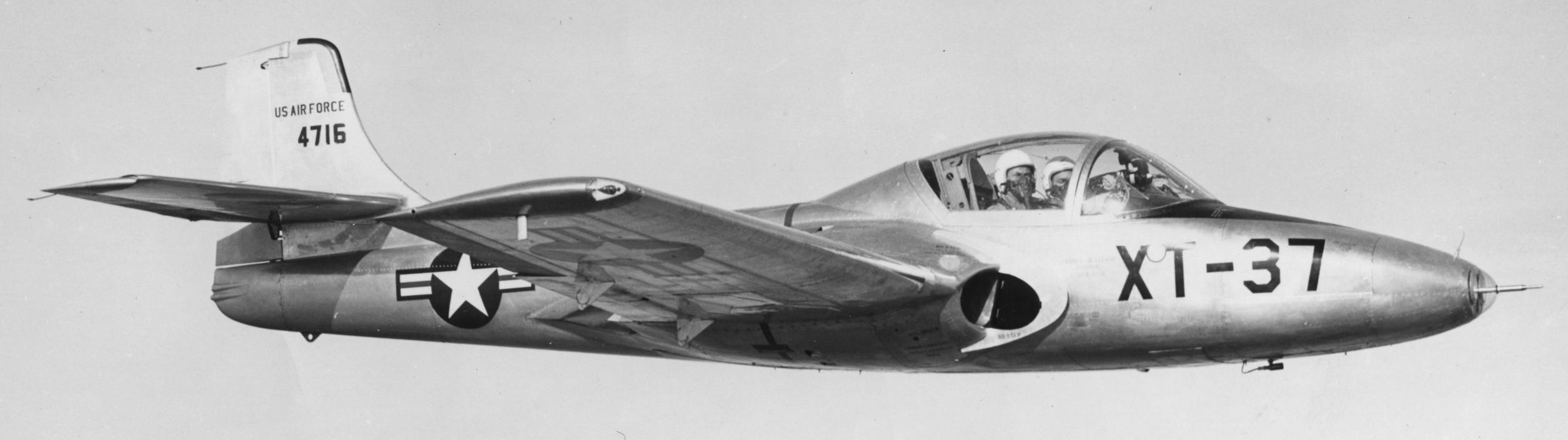 |
| Cessna T-37 |
Around this time the Air Force transferred the operation of a test facility built for Packard during WW II to Continental and I gave up the flight test job and moved to Toledo. I was given the responsibility for Turbine component development and my friend was given the responsibility for compressors. He had an experimental compressor built that he thought would be a world beater and it was ready for test. In those days prior to 5-axis NC mills, making a compressor rotor was a time consuming task. You first made a 10X pattern and then using a pantograph mill, you slowly milled each blade and then finally filed and polished the surfaces. He built it up on a 1,400 HP test rig but had vibration problems so he removed all the housings and proceeded to just run up the rig with only the rotor installed. He also decided to run it backwards to minimize the air pumping. It still made a great deal of noise and a number of us rushed to his control room to see what was happening. As I arrived, I saw the retaining nut leave the shaft and drop to the floor. Before the rig could be shut down, the rotor left the shaft and fell straight down unto the concrete floor. It stayed there jumping up and down a little. Suddenly it got traction and ran across the floor until it hit the wall. It then climbed the wall, ran across the ceiling, and down the opposite wall. It made one more complete revolution of the cell and then flipped on its back and spun for several more seconds. Unfortunately, my friend failed to account for the direction of the thread on the shaft and nut. It was designed to tighten if there was any slippage when turned in its normal direction.
Somewhat later, I heard about a small gas turbine start up in Detroit called Williams Research and I became their 18th employee. I spent the remaining 30 years of my career there working on a variety of turbine engines including automotive turbines for Volkswagen, Cruise Missile turbofans and finally turbofans for executive aircraft.
One incident that stands out concerns work we were doing developing a low cost governor for aerial target engines. One of the engineers designed a system that utilized a simple centrifugal pump rotor that could be directly shaft mounted and a pressurized fuel tank. By raising the pressure in the tank above the head generated by the pump the fuel would flow backwards through the pump and the engine would accelerate until the pump head, flow and engine requirements matched. We spent the morning characterizing the system using a small turbojet engine that had a maximum RPM of 60,000 and developed 170 pounds of thrust. The system governed remarkably well and we decided to evaluate the effects of cold fuel. We packed the fuel tank in dry ice and went to lunch. Later in the day we started the engine and were sitting at idle and noticed the RPM slowly increasing. I first tried dumping the pressure in the tank, however the morning’s running had depleted most of the fuel in the tank and the tank was mainly full of air under pressure and the dump line was small. Next I turned off the power to a shut off solenoid in the fuel line between the tank and the engine. Unfortunately the solenoid didn’t like the cold and it remained open. Meanwhile the speed was slowly increasing. I then rushed into the test cell with a hammer and delivered a few solid blows to the solenoid with no effect. By now the speed was approaching the max allowable and the engine was still slowly accelerating. At this point all the interested observers departed the area not wanting to be involved in the impending disaster. My technician, who was a mild mannered gentleman from the South, grabbed a pair of slip joint pliers and rushed into the cell. He pinched the fuel line with both hands and hung on. The RPM stabilized and then slowly began to decline as the pressure in the tank bled off. He had saved the day. The problem was caused by the O-ring on the shaft seal becoming stiff with the cold fuel not allowing the seal to follow the movement of the shaft. The fuel leaked directly into the inlet air stream and burned when it arrived at the burner. Although this test had been intended to be a quick check of the concept only, it did point out the need for more thorough planning.
Send mail to
![]() with questions or comments about this web site.
with questions or comments about this web site.
![]()