Waste Heat Utilization in High Output Aircraft Piston Engines
by Robert J. Raymond
Published 27 Nov 2019
|
1. Introduction This paper follows the development of the various ways in which the energy in the exhaust of high output aircraft piston engines was utilized from the WWI era, with the development of the turbo-supercharger, to the final developments in the immediate post WWII period with the introduction of the turbo-compound engine. A number of uses for the energy in the exhaust and heat rejection systems were attempted and most of these found some application in various aircraft. These will be discussed and examples of the technologies will be given. By the end of WWII liquid cooled engine development was almost exclusively dedicated to military applications. The attempt by Rolls-Royce to commercialize their liquid cooled Merlin engine in the Canadair DC-4 was not successful. The only large liquid cooled engine to find new applications in the post WWII era was the Rolls-Royce Griffon. The commercial market post WWII was dominated by air cooled engines; in the USA by Pratt &Whitney and Wright Aeronautical and in Britain by Bristol and, to a lesser extent, Alvis. |
In the USA the design of Wright’s R-3350 and the Pratt & Whitney R-4360 began during or slightly before WWII. Major work on the turbo-compound version of the R-3350 occurred after the war. By the late 1940s it was obvious that the gas turbine and jet engines would be formidable competitors due to the high thrust per unit weight they could provide. As a consequence the piston engine manufacturers who opted to compete concentrated on the relative fuel consumption advantage they had over the gas turbines of that period. As a consequence, the commercial aircraft and the engines that powered them adopted the technology brought to a high state of development during WWII, namely turbo-supercharging. By the late 1940s most of the large commercial aircraft were turbo-supercharged and turbo-compounding followed soon after. This paper will follow that evolution and discuss the ways in which exhaust and cooling system energy was used. |
|
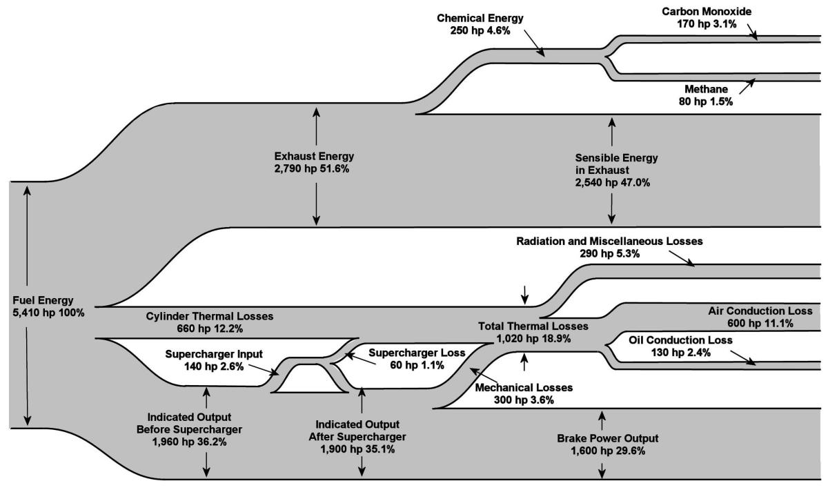
2. Sources of Waste Heat Figure 1 shows a heat balance for the Wright Cyclone turbo-compound engine for cruise conditions[1]. The efficiency at the brake (or propeller input) is close to 30%, a very respectable number for an engine with a compression ratio of 6.7:1. Some of the fuel energy shows up as “chemical energy, which is the energy lost due to incomplete combustion of the fuel, but all of the other losses end up as heat losses and could presumably be recovered. |
Recovering losses related to the high exhaust gas temperature after it has expanded to atmospheric pressure is very difficult if not impossible in aircraft because it would require another cycle operating in tandem with the aircraft engine’s, such as Rankine or Stirling, which require their inefficiencies to be rejected through a heat exchanger as well as incorporate a second large heat exchanger to recover the heat from the engine exhaust and transfer it to the working fluid of the additional cycle. These heat exchangers would be excessively large and heavy for an aircraft application. This arrangement is known as a bottoming cycle and, aside from ocean going vessels, has only found stationary land based applications where the prime movers are usually a gas turbine and Rankine cycle (steam). |
|
| Fig. 1 Wright Cyclone 18BD Heat Balance at Cruising Power, 1,600 bhp, 2,300 rpm, 0.068 fuel-air ratio. (Author) |
|
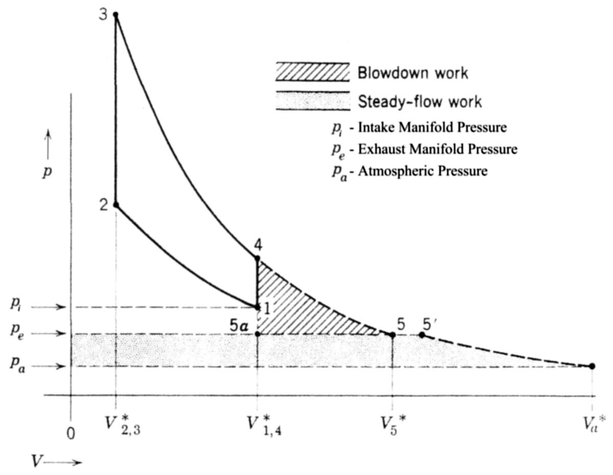
Figure 2 is a pressure-volume diagram for the engine cycle that shows the work available both in the blowdown and steady-flow exhaust processes[2]. It is possible to combine both sources but no such configuration was commercialized. Note that as the exhaust pressure approaches the atmospheric pressure a larger percentage of the blowdown work becomes available. The volumetric efficiency of the engine declines as the exhaust pressure approaches the intake pressure, particularly when the valve overlap is high, and this has a negative impact on air flow and power output. The pumping work (getting the exhaust gas out and fresh air into the cylinder) increases as the exhaust pressure approaches or exceeds the intake pressure and this also reduces power and efficiency. Since the engines under consideration here had relatively high overlap (90° for the Cyclone) the selection of an exhaust recovery system had to keep these considerations in mind. A secondary source of heat recovery is the oil and cooling systems of liquid cooled engines. An analysis of the Messerschmitt ME-109 in a captured French wind tunnel indicated the coolant radiators accounted for over 14% of the total aircraft drag [3]. As we shall see, this was considerably more than it would have been if the radiator and its enclosure had been carefully designed. |
|
|
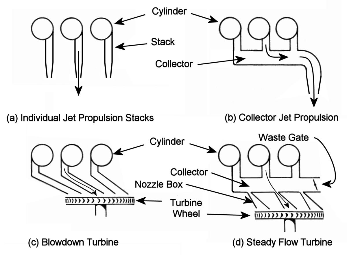
3. Utilization of Waste Heat 3a. Introduction Attempts to utilize the energy in the exhaust originate in the very early history of the aircraft engine. As early as WWI the turbo-supercharger was installed in French and American aircraft. This device consisted of a turbine driven by the exhaust gas and coupled to a compressor for supercharging the engine. After WWI, in the USA, its development was picked up by the National Advisory Committee on Aeronautics (NACA) and the Army Air Corps at Wright Field. The NACA work consisted of extensive testing of engines to determine the effects of operating variables on performance. The variables most likely to affect the overall performance of the engine/heat recovery system are the ratio of exhaust to intake manifold pressure and valve overlap. These variables influence the air flow (volumetric efficiency), detonation limit and exhaust temperature, the latter having an impact on turbine durability in turbo-supercharge and turbo-compounding applications. Work to support these efforts was eventually given to universities as well. This developmental work led to the adoption of turbo-supercharging in military aircraft in the mid to late 1930s. Figure 3 shows the options available in the recovery of energy in the exhaust and all were used in American engines in one form or another[4]. A German engine used a modification of the jet ejector system to induce additional air flow through the engine housing of an air cooled engine. All of these variations will be discussed in what follows. |
|
|
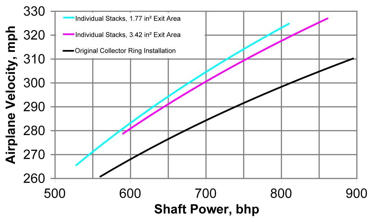
3b. Added Thrust A significant increase in thrust can be realized by the simple expedient of pointing the exhaust stacks toward the rear of the aircraft. This only becomes effective at aircraft velocities above around 250 miles per hour. Figure 4 shows the results obtained by the NACA in 1940 on an XP-41 aircraft with an R-1830 radial air-cooled engine[4]. In addition to the collector ring that directed all of the exhaust vertically downward from the bottom of the cowling, individual stacks pointing rearward were tested with two different nozzle sizes. An analysis of Figure 4 at 300 mph indicates that the thrust from the engine’s propeller is about 850 lb with the collector ring and 744 lb with the individual stacks. At 700 bhp the ratio of change in thrust to engine brake horsepower is 0.15. Tests of exhaust stacks at Rolls-Royce by Hooker [5] indicate that the Merlin could achieve added thrust on the order of 0.13 pounds of thrust per engine brake horsepower. Hooker carried out a complete analysis of the engine’s sensitivity to back pressure and designed its stack nozzle accordingly. A rule of thumb given by Hoerner [3] is that between 0.11 to 0.13 pounds of thrust per horsepower can be expected from properly directed exhaust stacks with the appropriate exhaust exit area. |
This technique for augmenting thrust was never adopted in commercial aircraft due to excessive noise. This was one of the problems with the Merlin equipped Canadair DC-4. An attempt was made to install fuselage-side manifolds that joined with the outboard bank. It is unknown to me if this succeeded in alleviating the noise problem but it seems likely that the thrust augmentation would have been negatively affected.
|
|
3c. Turbo-supercharging Despite the fact that the turbo-supercharger was a French invention dating from 1910 the USA can rightly claim to have made it a viable and effective device. The engineers at Wright Field saw its potential and undertook an aggressive program of development. Figure 5 shows an early turbo-supercharger installed on a Liberty engine[6]. Note that the exhaust turbine is located between the engine and compressor. This configuration was plagued with a very high component temperature problem that was overcome in the installation on a Curtiss D-12 engine shown in Figure 6. The turbine is now on the outboard side supported by a single bearing. This arrangement allowed more effective air and radiation cooling and is the same configuration used in today’s turbochargers. |
The British equipped single models of their Bristol Hercules engine with a turbo-supercharger ca. 1942. This was apparently a version of the Hercules VIII designated XVMT. It does not appear to have been used to any great extent [7]. Napier also experimented with turbo-supercharging in 1927 in their Lion IV but abandoned development[7]. I have no information on the origins of the turbo-supercharger they used. |
 |
 |
| Fig. 5. Early Turbocharger on Liberty Engine<br />(U.S. Army Air Service) | Fig. 6. Later Turbocharger Design with Exposed Turbine Wheel<br />(U.S. Army Air Service) |
|
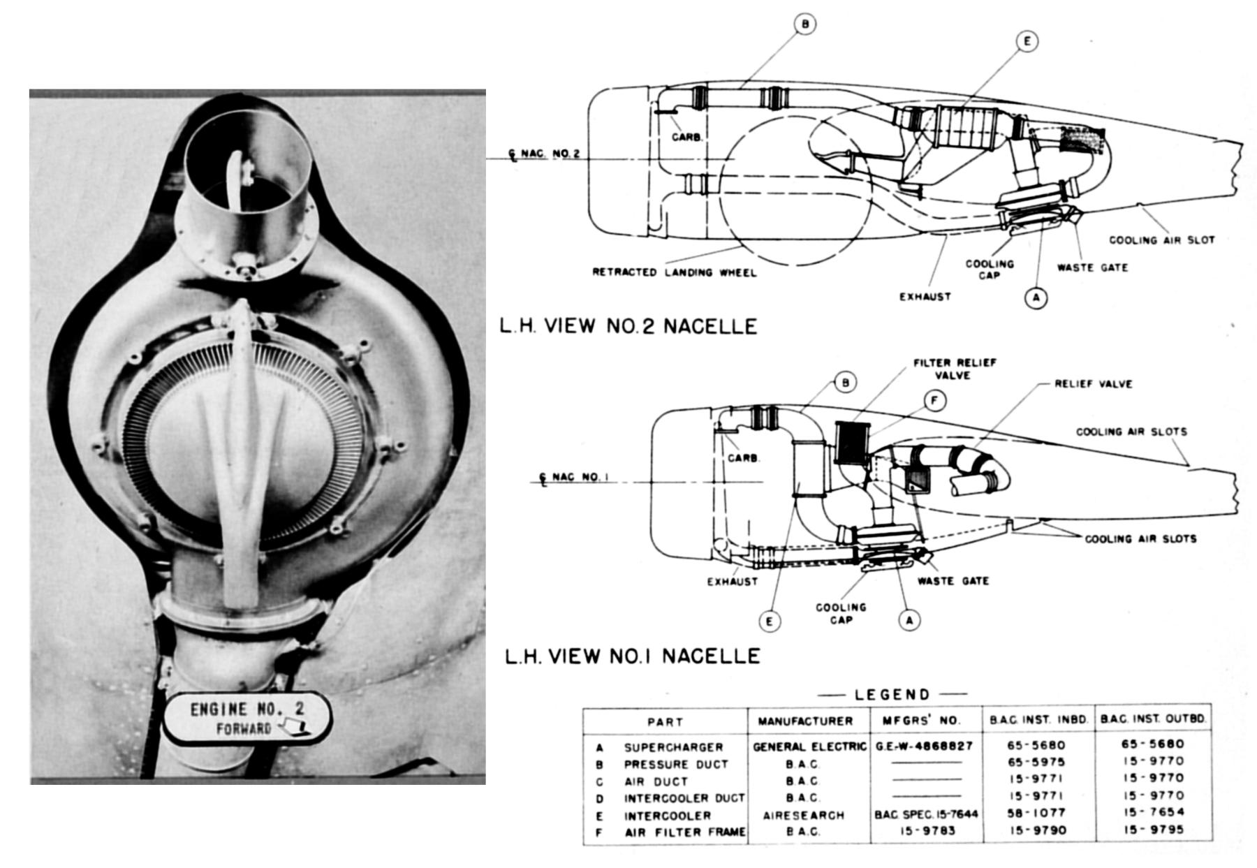
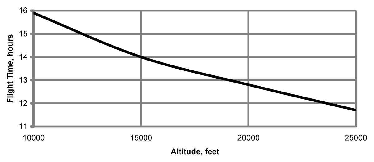
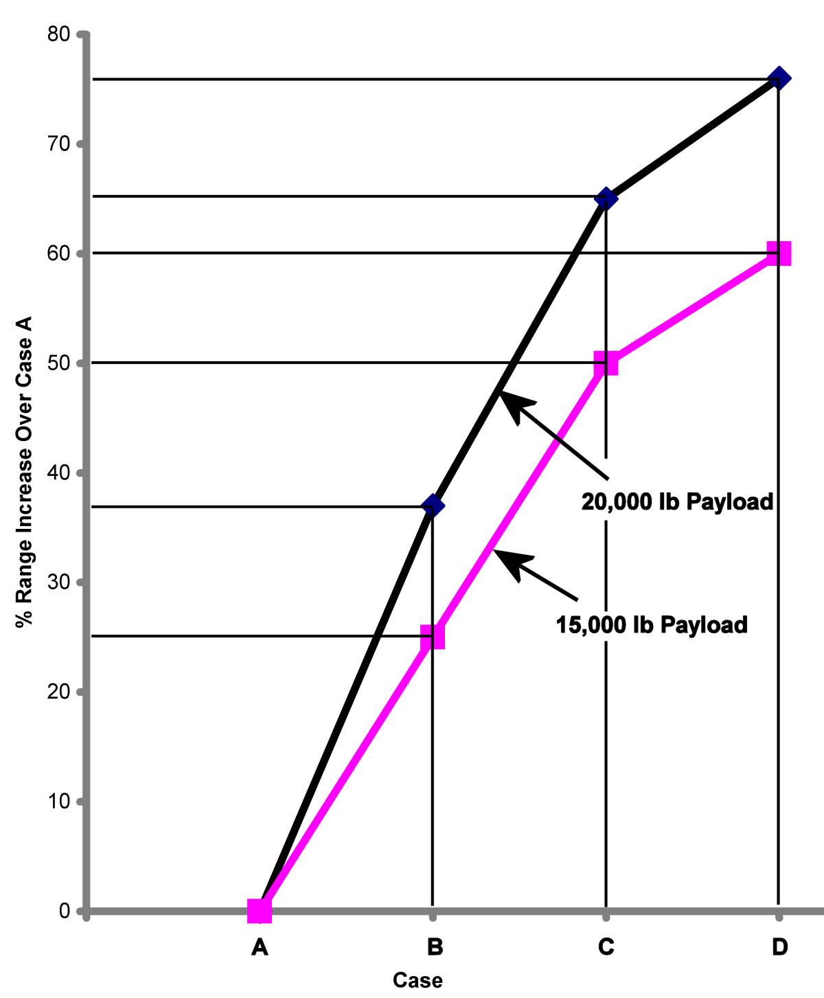
BMW built turbo-supercharged versions of their 801 engine in 1943 but these were apparently unsuccessful and suffered from a shortage of the high temperature alloys necessary for a successful turbine. BMW’s gas turbine activity probably contributed to this shortage. The development of the Boeing B-17 bomber was started in the early 1930s and progressed through various models[8]. In 1937 the Army Air Corps requested a model of the B-17 equipped with turbo-superchargers, which were eventually adopted. Figure 7 shows the arrangement of the turbo-supercharger in both engine nacelles and a photograph of its installation in a B-17[8]. The aftercooler is item “e” in this figure. By the end of WWII the B-24, B-29, P-38 and P-47 aircraft were all equipped with turbo-superchargers. The enhanced performance provided by the turbo-supercharger in both altitude and speed did not go unnoticed by the commercial aircraft manufacturers who saw its potential. By the end of WWII the turbo-supercharger had reached a state of development that made it a viable option for commercial airlines. Figure 8 gives the time of flight versus altitude at cruise conditions for a 3,500 mile flight and shows why the ability to fly at a high altitude would be attractive to an airline[8]. Figure 9 shows the range capability of the various supercharging configurations indicated in Table 1[8].It is interesting that Boeing’s analysis shows the two stage, two speed supercharger (engine “B”) as being heavier by 184 pounds than the base engine with a cruising turbo-supercharger (engine “D”). Perhaps another reason the Merlin didn’t make it in commercial applications? The question remains as to why this device was not adopted to the level it was in the USA by manufacturers in any other countries. I’m speculating here but it seems that once the turbo-supercharger had proven itself in WWII no other countries had the resources to play catch up. The British saw the advantages of the jet engine relatively early and put much more effort into its early development than the USA. The same can be said of Germany but by the end of the war the Germans did not have the resources to pursue its development. Today Rolls-Royce remains a very strong player competing with General Electric and Pratt &Whitney in the large engine market. |
|
 |
 |
| Fig. 9. Range Comparison: 25,000 ft Altitude, Fixed Payload, 295 mph (Author) |
|
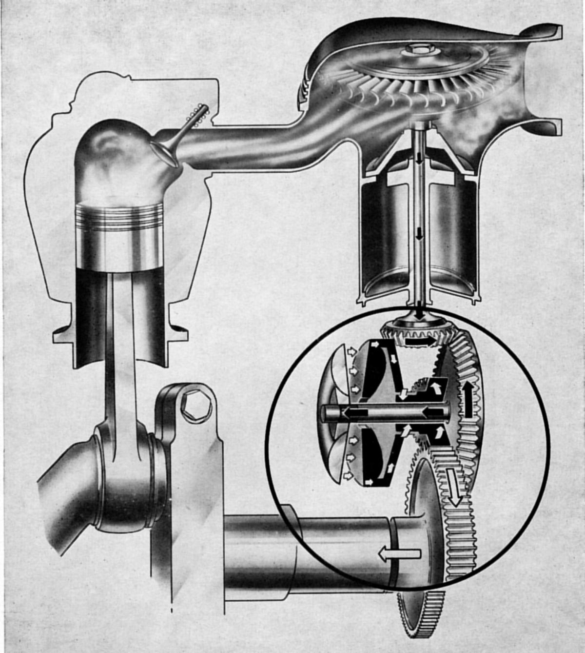
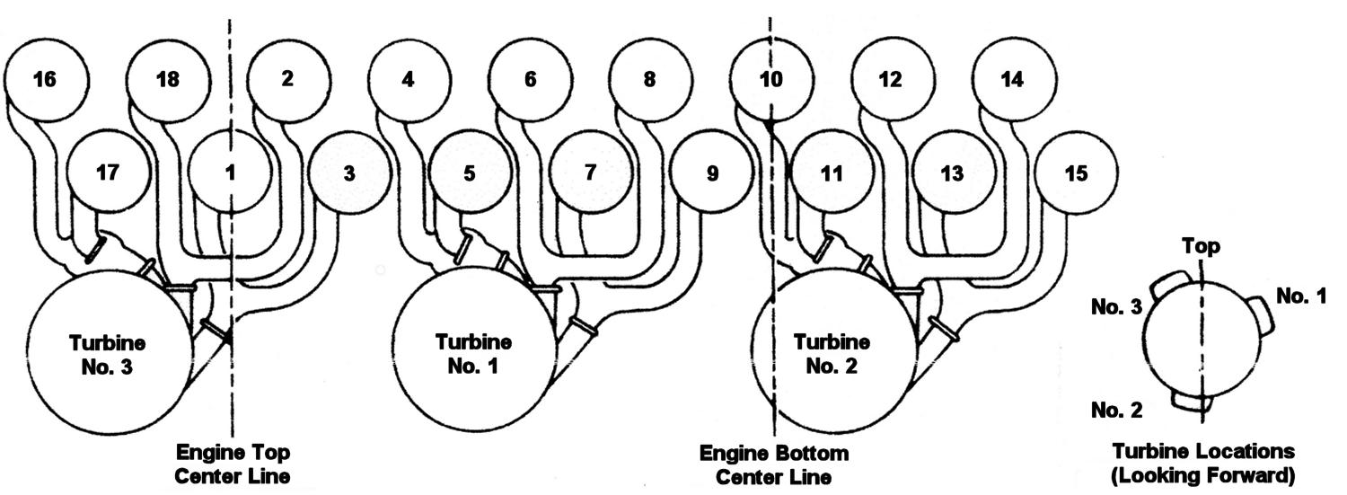
3d. Turbo Compounding The term turbo-compounding refers to the configuration where the exhaust driven turbine delivers power back to the engine drive train rather than to a free floating compressor as in the turbo-supercharger. The configuration can be as shown in either Figure 3c or 3d. As mentioned above, the two could be combined where the exhaust from the blowdown turbine wheel is directed to the steady flow collector box. I know of no applications with that configuration but the NACA did extensive analysis of it based on their testing of blow-down turbines[9 and 10]. The Wright Aeronautical Division of the Curtiss-Wright Corporation took the lead in turbo-compounding development post WWII based on their R-3350 engine. This 18-cylinder double-row engine was, by the time turbo-compounding development was underway, equipped with in-cylinder fuel injection that allowed large valve overlap and high pressure differentials between intake and exhaust manifold without loss of fuel in the exhaust[11]. This reference gives an unusual amount of detail regarding their developmental effort on this engine. These include valve, valve guides, valve seats and cooling fin area increases, as well as turbine development. Figure 10 shows the one of three R-3350 blowdown turbines with its associated drive-train, Note the fluid coupling to isolate the turbine from any engine induced torsional vibrations. To be as effective as possible the blowdown system should have no interference between the exhaust pulses from the individual cylinders. With six exhaust turbines, Wright’s initial configuration, there were three cylinders per turbine allowing one exhaust pipe per cylinder, i.e. no siamesing of the cylinders and substantially cooler turbine blades due to the longer period between exhaust impulses. The three turbine arrangement finally adopted was substantially lighter and less costly to manufacture. It joined two exhaust pipes together from cylinders whose exhaust pulses did not overlap. The final arrangement is shown in Figure 11. Four of the six cylinders per turbine wheel are joined in the conventional manner but the remaining 2 exhaust pipes (4 and 5, 10 and 11 and 16 and 17) serve cylinders with 95° of exhaust overlap. To prevent backflow and the possibility of disturbance these two cylinders were connected with an ejector installed in the pipe from the rear cylinder that begins its exhaust pulse as the front row cylinder ends its pulse thereby acting to aspirate the front row. The entire turbine system is quite complex comprising its drive train, cooling and lubrication systems. A detailed description of its design and development is beyond the scope of this paper and the reader, if interested, is encouraged to obtain a copy of Reference 11, readily available from the Society of Automotive Engineers.
|
|
|
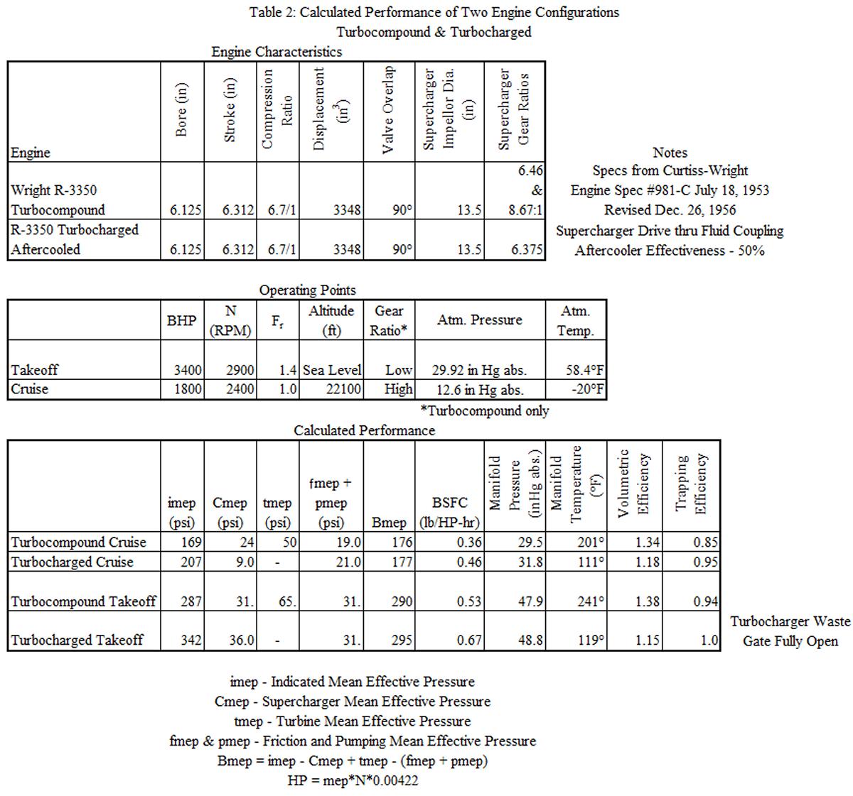
3e. Turbo-Supercharging versus Turbo-Compounding The first shipments of the turbo-compound R-3350 occurred in March of 1950 [11]. The engine would shortly be adopted in a number of commercial and military applications. In the 1950s there were three large passenger aircraft used in airline operations. These were the Lockheed Super Constellation, the Douglas DC-7 and the Boeing Stratocruiser. The Lockheed and Douglas aircraft were equipped with the R-3350 Turbo-Compound engine and the Boeing used the turbo-supercharged Pratt &Whitney R-4360. This choice by Boeing probably had a good deal to do with their experience with this configuration in the B-29 and B-50 military aircraft[8]. As an exercise and to validate my performance analysis technique I thought it would be interesting to compare the two systems at take-off and cruise conditions. To make it a fair comparison I substituted the stock R-3350 for the R-4360 so as to eliminate any differences in the characteristics of the two engines like friction and volumetric efficiency and equipped the turbo-supercharged version of the R-3350 with the gear ratio and supercharger fluid coupling drive used in the R-4360. Table 2 gives the specifications of the two configurations. Methodology This will be a brief outline of how I carried out the analysis. The air flow relies on a calibration of this characteristic for the R-3350 carried out when the engine was being evaluated for the in-cylinder fuel injection system eventually adopted[12]. When this data was obtained the valve overlap of the R-3350 was 48° and had been increased to 90° by the time the turbo-compound engine was introduced, which necessitated a correction to the computation[13]. The result was an air flow, volumetric efficiency and trapping efficiency (quantity of air retained in the cylinder for combustion). The assumption made for the fuel-air ratio at the two conditions is given in Table 2 and with the compression ratio this sets the indicated efficiency for the ideal fuel-air cycle. The actual cycle was assumed to be 90% of the ideal cycle (probably slightly high but the same assumption held for both versions of the R-3350). The friction characteristic of this engine is based on my analysis of what data was available, the most complete being for the Allison V-1710. The NACA seemed to use the same curve of friction and pumping mep versus piston speed for both air cooled and water cooled engines in their analyses so I have used the curve for the V-1710 in this analysis. This curve of friction and pumping is for the intake and exhaust pressures equal and at atmospheric pressure. The correction for differences in these two pressures is based on data in Reference 2. The performance of the supercharger compressors and the steady flow exhaust turbine are based on performance maps for the period we are considering[2]. The blowdown turbine performance is from References 2 and 10. The procedure involved guessing a manifold pressure to get the desired bmep for the power required and working through the performance of the turbo-machinery and other operating characteristics to get the bmep. It usually took three or four trials to converge on the desired value of bmep. This is why the bmep values in Table 2 at the desired conditions are not quite the same. These differences would have negligible effect on the BSFC. The resulting values of air flow and pressure ratio were used with the performance maps of supercharger and turbine so that the size and speed of the supercharger conformed reasonably close to the values shown in Table 2.
|
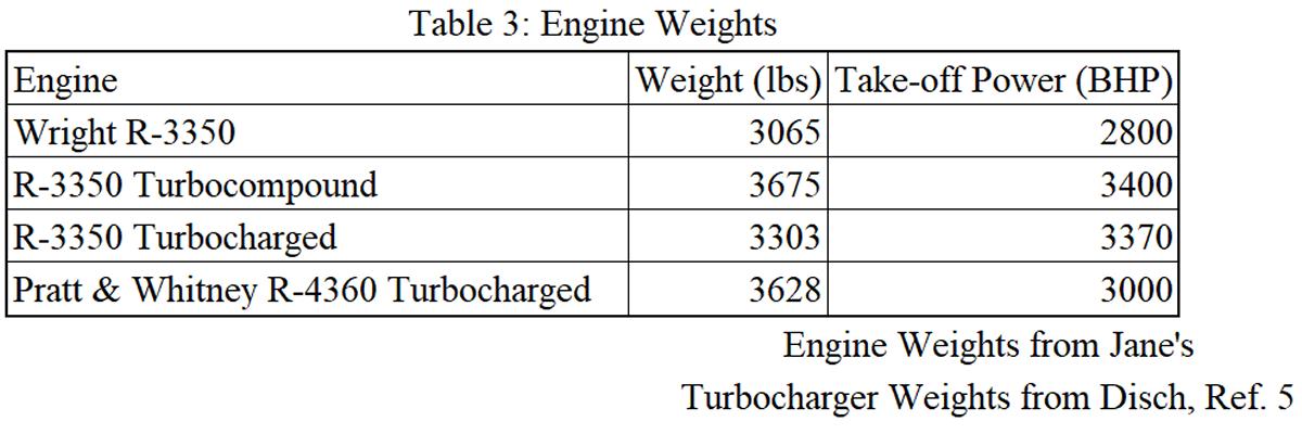
Results The results of this analysis are shown in the third part of Table 2. The cruising fuel consumption for the turbo-compound configuration is 0.36 lb/bhp/hr versus 0.46 lb/bhp/hr for the turbo-supercharged version. This represents about a 22% improvement for the turbo-compound engine over the turbo-supercharged engine. The cruising BSFC of the turbo-supercharged R-3350 is given in its specification as 0.46 lb/bhp/hr and the best BSFC for the turbo-compound R-3350 given in the specification on Table 2 is 0.38 lb/bhp/hr, which still represents an improvement of 17%. The probable reason my number (0.36) is low for the turbo-compound engine is that I have overestimated the efficiency of the blowdown turbines and their drive-trains. I have listed other performance parameters in Table 2. The blowdown turbine is contributing 50 psi to the total bmep at the cruise condition while the turbo-supercharger reduces the engine driven supercharger mep by about 15 psi and the friction and pumping meps is 2 psi higher because the exhaust manifold pressure is higher. The BSFCs at the take-off condition are lower than the maps for these engines indicate mainly because they actually run considerably richer mixtures than I assumed in the analysis to avoid detonation and reduce the exhaust temperature. I used the value of 1.4 because it was the richest mixture for which I had indicated efficiency data. The manifold temperatures for the turbo-supercharged engine are lower because it was assumed to be equipped with an aftercooler as indicated in Table 2. For a 3,500 mile flight at 340 mph with each engine producing 1,800 horsepower the total fuel saving with the turbo-compound engine is about 5,000 lb. In addition to the fuel saving it would be possible to carry 5,000 lb more in cargo/passenger weight. The take-off weight for the aircraft in which these engines were installed was 110,000 lb to 145,000 lb. The purchase price of these two configurations is not known to me but that would undoubtedly influence the buyer as well as the difference in performance. Table 3 gives my estimates of the weights of these engines equipped as indicated. The difference in weight between the R-3350 Turbo-compound and the R-4360 turbo-supercharged was probably less than 50 lb. As a conclusion to this discussion of turbo-charging and turbo-compounding I would like to include the following remarks from References 11 and 14. At Allison experiments had been carried out with a turbo-compound version of the V-1710 utilizing a steady flow turbine. This engine had a minimum BSFC of about 0.40 lb/bhp/hr. At the end of their paper, written in 1948, the authors wrote the following summary of their work: “Despite the revolutionary results obtained in the exploratory tests, it was decided to drop further development of the compounded reciprocating engine, as it was felt that the engineering manpower that would have been required to bring the compound engine to a practical stage would be better devoted to developing the turboprop engine”[14]. In a 1954 paper[11] the Wright engineers wrote the following in the final paragraph: “Future prophets predicting the demise of the reciprocating engine should take note that past prophets have not been too successful. When one considers the overall costs, fuel consumption, high initial cost, and the inherent operating problems of turbine-powered aircraft, it is difficult to conceive that the piston-engine transport will become an extinct species within the next 10 years. Consequently, our development of the Turbo Compound engine is proceeding industriously and will result in considerable increases in both cruise and take-off horsepower. Application of these advanced engines to transport airplanes will continue to provide fast, efficient, and profitable transportation for many years to come”. These two excerpts show how a very successful company can lull themselves into a false sense of the correctness of their path forward. This example is not unique in the history of business, particularly when it’s a pioneer in its field like Wright. We know which of these is still in the aircraft engine business.
|
|
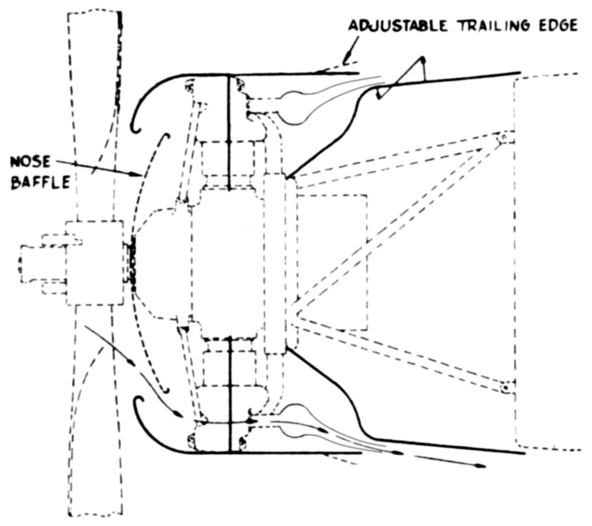
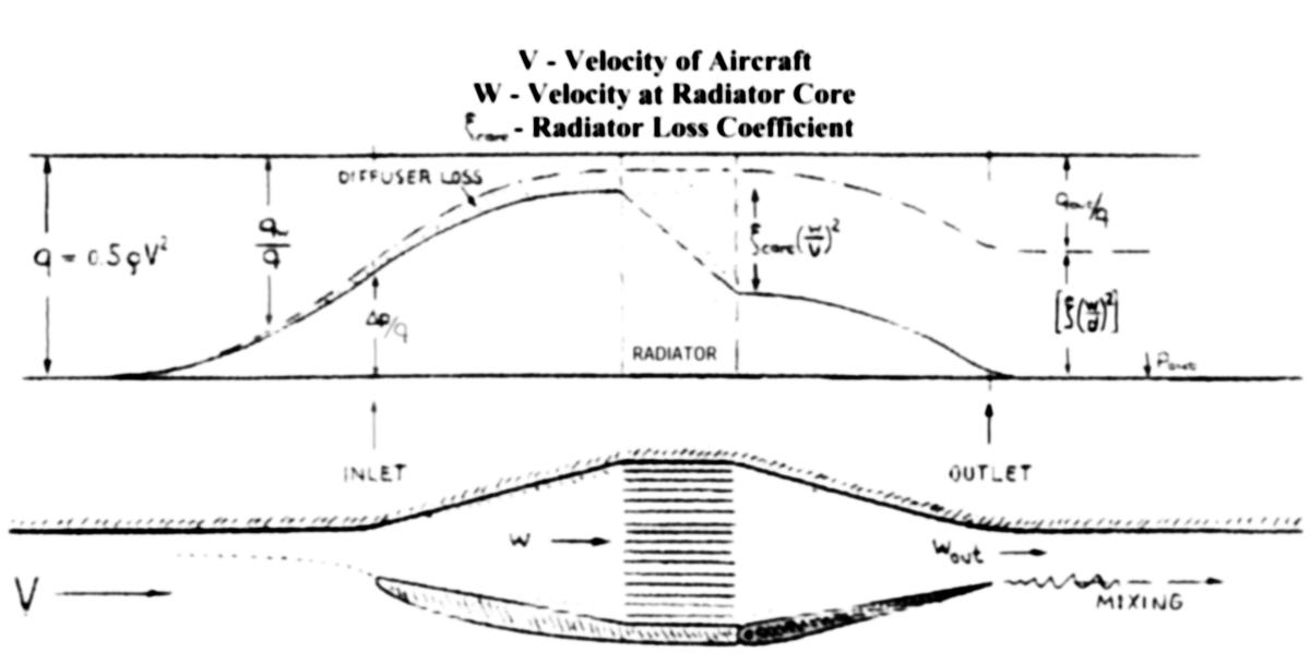
3f. Increasing Cooling Air Flow Two very important sources of drag in an aircraft are, in the case of aircraft powered by air cooled engines, internal drag through the engine nacelle and, in liquid cooled engine installations, the internal drag from coolant radiators. Figure 12 is a cross section through the nacelle of an air cooled engine installation. The circular exhaust manifold is tapped in several or more locations with short pipes directed into the cooling air outlet from the nacelle. This creates a jet pump or ejector effect, which enhances the air flow through the nacelle. I have found no references to the use of this technique in American aircraft. The BMW 801 engine shown in Figure 13 used this principle along with a fan at the entrance to the nacelle to increase air flow[15]. I have found no information as to how effective this technique was in increasing nacelle air flow. One other way in which waste heat has been claimed to have a beneficial effect is in the coolant system radiators of liquid cooled engines. The ducted system depicted schematically[3] in Figure 14 shows the losses in total pressure that occur as the cooling air passes through; the radiator core being the largest. Figure 15 shows the arrangement in the Messerschmitt Bf 109. |
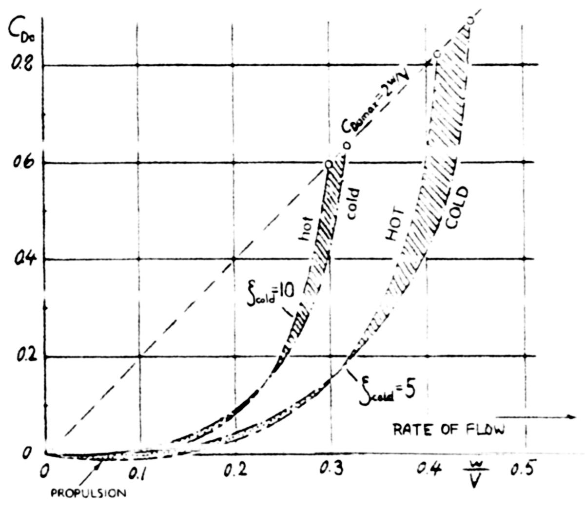
It is obvious that this has the potential to behave as a ram jet and provide thrust rather than drag if the losses are low and sufficient heat is added at the radiator. This came to be known as the Meredith effect after an engineer at the Royal Aircraft Establishment published a paper discussing this effect in 1935. Hoerner[3] has compiled a very significant body of data on all types of aircraft drag including the internal drag induced by cowlings and ducted radiators. Figure 16 shows the results of an analysis of a ducted system for two radiator resistances, which cover the range of those investigated by Hoerner. The ordinate is the drag coefficient based on radiator core area and the abscissa is the ratio of air velocity at the radiator core to the velocity of the aircraft. Typical values of this ratio are 0.3 at climb and 0.1 at cruise. It is interesting that at values above 0.3 hot coolant causes higher drag than cold. This Figure indicates that at cruise conditions negative drag (positive thrust) is theoretically possible. It doesn’t seem likely that anyone flying a P-51 would notice this small change from positive to negative drag even if it did occur. The wing mounted duct of the Bf 109 had a very high total drag coefficient(internal and external drag) of 0.18, which Hoerner attributes to “blunt shape, external roughness and internal leakage”. A similar analysis for air cooled engine nacelles gives values of 0.1 for the drag coefficient at climb and 0.04 at cruise. It would appear that, while the associated structures (cowlings and heat exchanger ducting) were made more efficient with time, engine heat rejection to the atmosphere did not provide any significant positive thrust contribution to aircraft performance. |
 |
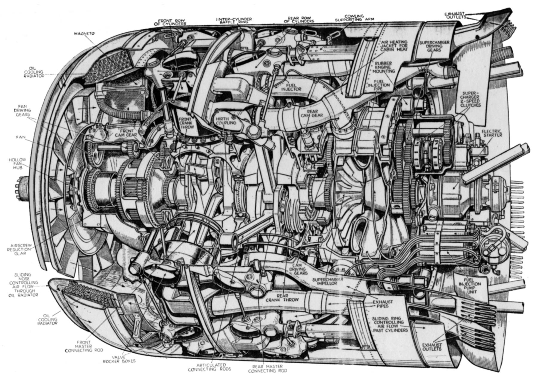 |
| Fig. 12. Illustrating Jet Pump Principle to Enhance Engine Cooling Airflow | Fig. 13. BMW 801 Engine with Cooling Airflow Enhanced by Exhaust Flow (Flight) |
 |
 |
| Fig. 14. Ducted Radiator System (From Hoerner[3]) | Fig. 15. Wing-Mounted Cooling Duct, Messerschmitt Me-109 (From Hoerner[3]) |
 |
| Fig. 16. Drag Coefficient versus Velocity Ratio for Two Radiator Resistance Values (From Hoerner[3]) |
|
4. What Might Have Been I couldn’t leave this subject without writing something about what was quite probably the most complex aircraft piston engine ever devised. The Napier Nomad was a flat 12-cylinder 2-stroke, loop scavenged, Diesel engine compounded with a 12 stage axial compressor and a 3 stage turbine. The coupling between the turbo-machinery and the engine was through an infinitely variable gear arrangement[16]. Figures 17 and 18 show views of the engine, which looks like a Napier Sabre with a gas turbine strapped to its belly where the other 12 cylinders should be. The infinitely variable gear-box is shown on the upper left side of the engine in Figure 18. This engine’s development was started after WWII so it was considerably behind the Wright Turbo-Compound, which had the advantage of some years of development of the engine before it was turbo-compounded. An advantage claimed for the Nomad was a broad tolerance for various types of fuel from gasoline to kerosene to Diesel fuel. I think gasoline unlikely unless it was of very low octane number. It seems obvious that Napier was intent on competing with the Wright engine. Its power rating at take-off was 3,046 versus 3,400 for the Wright engine and the specific weights were 1.18 versus 1.08 lb/hp respectively. The minimum fuel consumption was projected to be 0.325 lb/bhp/hr at 23,000 ft. |
The bore and stroke were 6.000" and 7.375" for a total displacement of 2,502 in³ This engine’s only airborn testing was in the nose of an Avro 4-engine bomber. Whether it ever made its horsepower or fuel consumption targets is unclear. A weight breakdown of this engine would be very interesting, especially that of the variable speed gear, which appears to be relatively heavy. Absent the turbo-prop, would this engine ever have been an effective competitor for the Wright Turbo-Compound? From an American commercial carriers point of view it seems unlikely. Airlines had long ago abandoned liquid cooling and the complexity of this engine would have been a very unattractive feature. Of course Napier never made a conventional engine. The Lion was the first with a W configuration, the Sabre was the first H-24 cylinder sleeve-valve engine and, after the Nomad, they designed their Deltic (not an aircraft engine), an 18-cylinder opposed piston two stroke Diesel in a triangular configuration with a crankshaft at each corner of the triangle. This engine was apparently a commercial success in boats and locomotives. |
 |
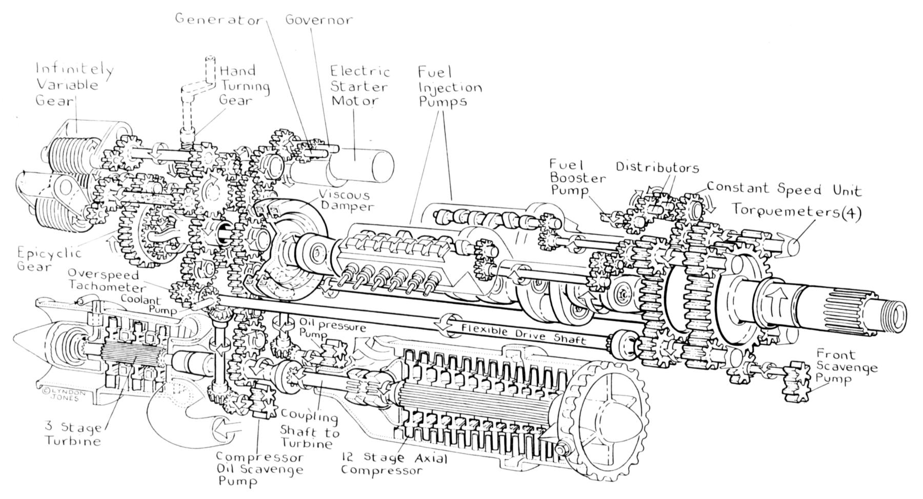 |
| Fig. 17. Napier Nomad Diesel Aircraft Engine Transverse Cross Section (Flight) | ig. 18. Napier Nomad Diesel Aircraft Engine Gear Train (Flight) |
|
5. Conclusions It is reasonably clear that an appreciable part of the advances described above were the results of two world wars and that these developments carried over into the commercial side, especially after WWII. The USA’s emphasis was on advancing the technology of piston engines and their high level of mass production as opposed to the German and British attempts to develop the gas turbine and jet engine. The many diverse programs the Germans had with both types of engine had the two sided effect of slowing down their development and production of piston engines during war time but putting the USA at somewhat of a disadvantage in the gas turbine field when the war was over. The fact that the allies won the war and America’s great contribution to that victory meant that the technology developed in Europe was immediately available in the USA, which they very quickly began to exploit. This left a gap at the end of the war when the advances in piston engine technology gave it some superiority over the gas turbine and a 15 year window to exploit that window until the gas turbine was ready and competitive for commercial applications. In reading this paper one will notice the many references to the NACA .That organization deserves much of the credit for researching and advancing these technologies. Their support of the turbo-supercharger development encouraged General Electric to manufacture this device along with superchargers. This in turn led to General Electric’s adoption of the British technology at the end of the war resulting in one of the worlds leading producers of large jet engines. One should also not ignore the contribution of the academic community to engine development. Many staff members at universities acted as consultants to engine manufacturers and received contracts from NACA and the Army Air Corps in support of their work. One outstanding example is the development of the tuned crankshaft torsional vibration damper by E.S. Taylor, an M.I.T. professor, acting as a consultant to Wright Aeronautical. This was a great era for the advancement of mechanical engineering in most of its disciplines and much of it due to the development of aircraft engines. |
6. References 1. Pierce, E.F. & Welsh, H.W. “Engine Compounding for Power and Efficiency” SAE Journal, Jan. 1948. |
Send mail to
![]() with questions or comments about this web site.
with questions or comments about this web site.
![]()