
The Evolution of Crankshaft Design
in High Output In-Line Aircraft Piston Engines
by Robert J. Raymond
Published 22 Sep 2017
Introduction
|
In piston engines the crankshaft functions to convert linear piston motion into rotating motion thereby making the work being done on the piston useful for turning a gear or propeller. While other devices for accomplishing the transformation of reciprocating to rotating motion have been attempted the crankshaft is universally used in piston engines today and was ubiquitous in high output aircraft engines. In in-line aircraft engines the crankshaft was usually the heaviest single component, which made it a target for weight reduction despite the constraints imposed by other design factors. These could include cylinder spacing (controls overall length), journal sizes to give adequate bearing area, and the necessity of providing counterweights to reduce bearing loads. Despite these constraints the Rolls-Royce Merlin crank with eight counterweights weighed only four pounds more than that of the Liberty-12 with no counterweights (107 versus 103 pounds). Both engines were close to the same displacement while the Merlin was finally rated at close to 2,000 horsepower and the Liberty at 420 horsepower. The Liberty was designed in 1917 and the Merlin design began in 1933. The crankshaft developed over a period of time when the ability to predict and measure stresses was very limited. There was limited knowledge of stress concentration factors and no practical way to measure stress in static tests of crank elements. All the designer had to go on was what had worked in the past. Nominal working stresses could be calculated based on estimated cylinder pressures and inertia loads and formal procedures for doing this were standardized by the U.S. Army Air Corps. Eventually, in the late 1930s, experimental stress analysis began to be incorporated into the design process. These techniques included the use of photoelasticity, brittle stress coat, mechanical extensometers for strain measurements and electrical strain gauges. Prior to the use of most of these devices, however, the fundamental evaluation of crankshaft design was established in important European work that subjected various crank configurations to fatigue failure. This work had an impact on the design of all types of crankshafts as well as German military aircraft engines and will be discussed further in this paper. |
The crankshaft is an excellent example of a complex and heavily loaded machine element. Its evolution encompasses a much longer period of time than we are considering here but the period of high output aircraft piston engines pushed its development faster than at any other time. In addition to design refinements this activity included forging techniques, metallurgy, heat treatment and the effects of shot peening and nitriding on the fatigue strength of the crankshaft. Figure 1 shows two attempts at eliminating the crankshaft, both with aircraft as the target market and both claiming low frontal area as their advantage. The first, the Fairchild-Caminez engine from the late 1920s, was actually certified and flight tested but had a very high fourth order inertia torque due to the two lobe cam and relatively heavy piston assemblies and was not pursued (1). The other engine shown is a barrel type known as the Alfaro engine and dates from the late 1930s (2). There have been many attempts at using the swash plate mechanism shown here in piston engines but none have been successful, usually due to the high stresses at the point of contact between the connecting rod and the cam or swash plate. Servicing such an engine would also appear to be a problem. One application in which this configuration has proven highly successful is in automotive air conditioning compressors where the loads are much lower than in engines. |
|
| Fig. 1. Two Prototype Aircraft Engines without Crankshafts |
Crank Configurations
 |
 |
 |
| Fig. 2. Four and Six Throw Symmetrical Crankshaft Arrangements | Fig. 3. Firing Orders and Torsional Vibration Characteristics for Three Engines | Fig. 4. Napier Sabre and "V" Engine Crankcase Construction |
|
A number of factors enter into the choice of the relative orientation of the cranks in the crankshaft of a multi-cylinder engine. These include:
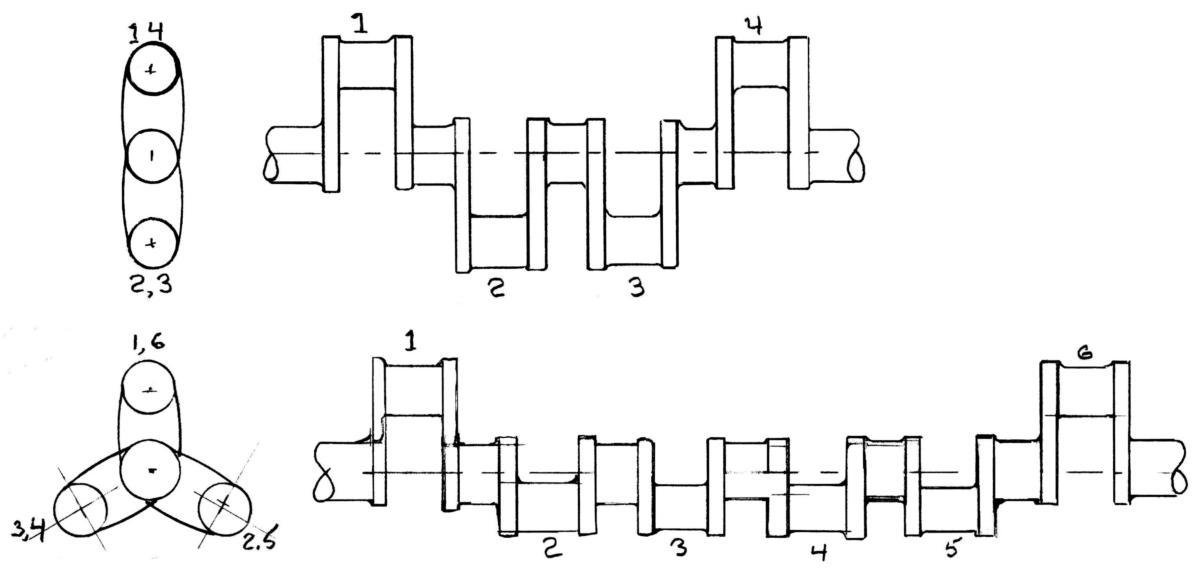
Some of these required that trade-offs had to be made and resulted in considerable development work in some engines. Our task is made somewhat easier due to the fact that most later engines had cylinders that were either 6, V-12, or flat twelve configurations all of which utilized a six throw crank as shown in Figure 2. The six throw crank is symmetrical; after the first three throws the three remaining throws are a mirror image of the first three. The only possible variation is if the pair of throws marked 3,4 are interchanged with the two marked 2,5. This crank gives completely balanced first and second order forces and moments. There are a large number of possible firing orders for this crank. The bank angle increases the possibilities but most were 60° with the notable exception of the Liberty 12 which had a 45° bank angle and an uneven firing order. As shown in Figure 2, the six throw crank has seven main bearings and all of the engines discussed in this paper had that number. The Curtiss K-12 had four main bearings and is the only aircraft engine with a six throw crank to employ that number of main bearings of which I am aware. Four main bearings on six throw cranks were much more common in automotive applications The four throw crank of Figure 2 is also symmetric about its center main. This is the configuration used in all modern in-line four cylinder engines and was used in the Hispano-Suiza V-8 aircraft engines of WWI and later. The Napier Lion, which was a W-12 with three banks of four cylinders, was also designed during WWI and went on to power aircraft into the late 1920s; it also used the flat, four throw crank with five main bearings as shown in Figure 2. The Hispano and Lion engines had unbalanced second order shaking forces due to this crank configuration. Modern V-8 engines utilize an anti-symmetrical shaft with throws at 90° and counterweights to balance the rotating masses, effectively eliminating first and second order forces and moments. The Wright company was a licensee of the Hispano engines and reportedly built a prototype with an anti-symmetrical crank to eliminate the second order forces but did not pursue this approach because they felt it added too much weight to the engine (3). In order to illustrate the choices that were made in choosing firing orders, crank orientations and counter-weighting I have chosen three V-12 engines from late in the era of the in-line configuration. These are shown schematically in Figure 3. The Rolls-Royce Griffon is the last engine of this type to be designed, developed and which saw extensive service post WW2. Note that none of these engines has the same firing order and the crank arrangement of the Rolls-Royce Merlin is different from that of the Allison V-1710 and the Griffon. Furthermore, the Allison engine initially had six counterweights, which increased to twelve in its later configurations, the Merlin had eight and the Griffon four. The question naturally arises, if these engines had no primary or secondary unbalance, why didn’t any arrangement within the limits imposed by the symmetrical six throw crank work as well as another? The answer is in the flexibility in bending and torsion of the crankshaft and crankcase. Examining Figure 2 one will see that the opposing throws of the crank elements create an internal bending moment that must be balanced at the main bearings unless the crank were infinitely stiff in bending. Similarly the reciprocating first and second order forces from piston motion must be balanced through the crankcase even though the net effect externally is zero. The crankcase, like the crankshaft, is not infinitely stiff and significant deflections occur when loads are applied to the main bearings. The crankshaft deflections can be somewhat mitigated with counterweights and most of the later engines had them, particularly when piston speeds were approaching 3,000 feet per minute. These were carefully evaluated to be large enough to minimize bearing wear without adding excess weight to the shaft. I know of no engines where the counterweights completely balanced the total rotating inertia. Even so, if the crankcase is too flexible the crankcase can go out of line with the shaft and cause edge loading on the bearings. |
The Griffon engine seems to have required considerably more development in this regard than either the Allison or Merlin (4). The crank arrangement and firing order given in Figure 3 represents the last of a long series of changes. The original Griffon had the same crank arrangement and firing order as the Merlin. The firing order was changed when fretting occurred in the quill shaft drive to the reduction gears and this was attributed to torsional vibration. Problems continued with cylinder head cracking due to excessive crankcase deflections. The crankcase was stiffened and the four-mass counterweight system was devised. The firing order shown in Figure 3 was finally adopted, the last of at least four iterations. The effect of firing order on torsional vibration is illustrated in Figure 3 by the phase angle diagrams for the various orders of vibration. The diagrams show how the contributions from the various cylinders combine to give the total excitation for a particular order of vibration. If the crankshaft were infinitely stiff in torsion only the major orders would be a problem since, as the minor order diagrams show, the excitation from the cylinders cancel each other. As Figure 3 indicates, the Griffon firing order changed all of the minor half orders. This is important in the two node mode of vibration where the front half of the crank is vibrating against the back half with a node in the middle. The phase angle diagram for the 1½, 4½ etc. minor orders illustrate this effect. For the Allison and Merlin the first three pairs of cylinders are working in phase with the final three while for the Griffon cylinders 2, 3 and 4, 5 are out of phase with the crank vibration thus reducing the torsional excitation. Apparently a Merlin was run with the Griffon firing order in 1945 and showed better torsional characteristics than with its conventional firing order. A previous examination of the torsional characteristics of the Merlin(5) indicates this was probably due to a reduced 7½ order in the two node mode at around 2,500 rpm. This brief summary of the effects of firing order and counter weighting serves to illustrate the complexity of the inter-relationship between the design choices confronting the engine designer. Many of the factors considered in this discussion were poorly understood until the mid 1930s and led to some very troublesome developments when, in the post WWI era, engines of higher power were attempted by increasing the number of cylinders. One such example is the Army Air Service W-1 engine the development of which began early in the 1920s (6). This engine was a W-18 configuration with 3 banks of 6 cylinders and a conventional 6-throw crank as in Figure 2. The engine was plagued with broken crankcase problems and valve train problems caused by excessive crankcase and cylinder deflections. The designers apparently never considered using counterweights to reduce the loads on the crankcase. The flat twelve configuration used in the Napier Sabre and Rolls-Royce Eagle sleeve valve engines benefited from the very stiff, box-like, configuration of the crankcase as seen in Figure 4. The long through bolts shown keep the entire crankcase in compression whereas in the V configuration the head bolts and main bearing cap bolts put the area of the crankcase around the main bearings in tension from firing pressure and inertia loads. The Sabre crank was designed to have counter-weights but these were found to be unnecessary and removed during development. The Eagle had counter-weights but utilized the Griffon crankshaft which already had counterweights so one wonders if they were necessary on the Eagle. It seems plausible that the Griffon represents the limit in displacement and brake horsepower per square inch of piston area for an in-line V configuration using an aluminum crankcase of acceptable weight, given the problems encountered in its development, and that the flat configuration of the Sabre and Eagle would have been the future if the development of this type of engine had continued. The IV-2220 engine under development at Chrysler during WWII was a V-16 of almost identical displacement to the Griffon. It had a slightly smaller bore (5.8" versus 6.0") and a much shorter stroke (5.25" versus 6.6"). Its crankcase was considerably longer than the Griffon’s due to the two extra cylinders in each bank and the increased cylinder spacing of the separate cylinder construction mandated by the Army’s Hyper program. The crankcase suffered from numerous failures during the engine’s development and the program was canceled before the engine was capable of meeting its performance goals (7). |
Crankshaft Design
|
Early aircraft engine designers had only automotive practice as a guide. Designers could observe what worked and make some guesses about how much lighter they could make their designs, then cross their fingers and hope. As progress was made in understanding the thermodynamics of the engine cycle and crude instruments were devised to measure peak firing pressure some analysis entered into the design procedure. Knowledge of cylinder pressures and the weights of the reciprocating and rotating parts allowed the calculation of torque and bending forces in the individual crank elements. Once again, any deflections in the crankshaft altered the way in which the journals were supported in the flexible crankcase and changed the loading in an unpredictable manner. However, the assumption of infinite rigidity allowed the calculation of nominal stresses in the cylindrical crank pin and journal and the more or less rectangular crank web and this procedure was formalized by the U.S. Army (8). Nevertheless, the stress concentration factors where journals and pins joined the crank web and at other irregularities such as oil holes and lightening holes in the journals and pins were unknown. |
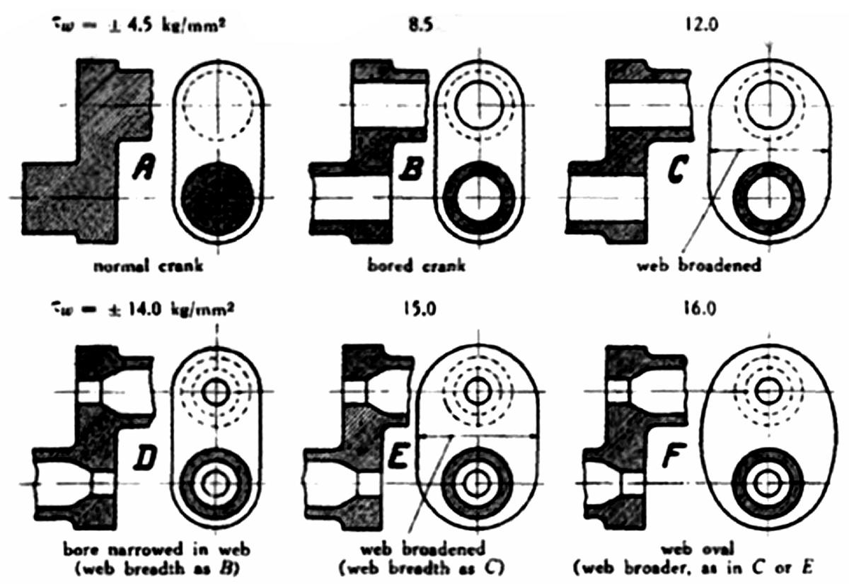
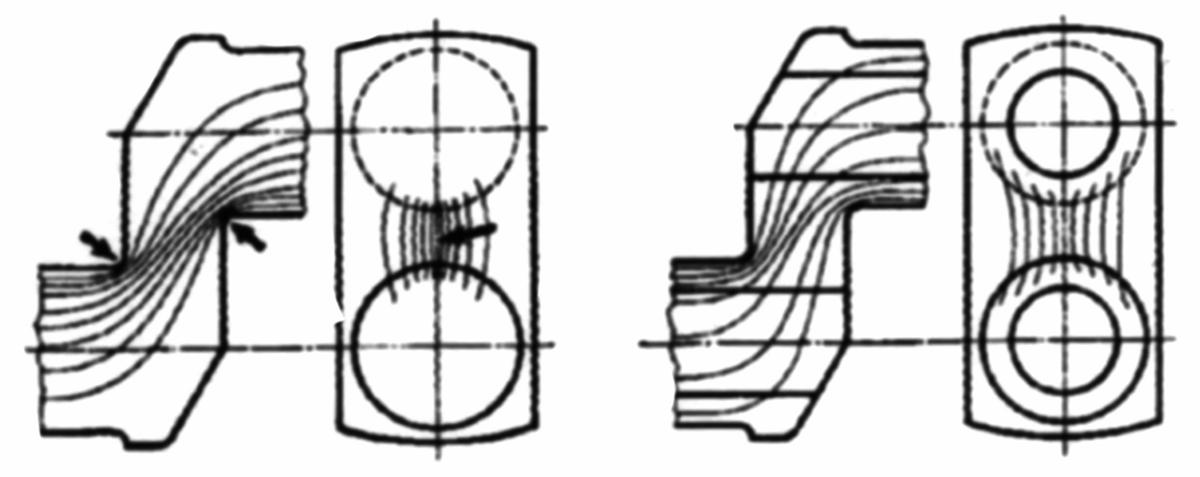
The situation changed in the mid to late 1930s with fatigue testing to failure of crank elements of various designs. Figure 5 shows some of these results (9). As can be seen in Figure 5 the bored pins and journals gave an almost two to one improvement in fatigue strength. Figure 6 gives a qualitative explanation of why this is so. The flux lines of the load are forced to spread to the remaining pin area and away from the pin-web juncture. One wonders if the engine designers of the WWI era had an intuitive feel for this effect or were they simply trying to make the crankshaft lighter? |
 |
 |
| Fig. 5. Influence of Shape on the Fatigue Strength in Torsion of Crank Elements | Fig. 6. Force Fluxes in Crank Elements |
Overlap
|
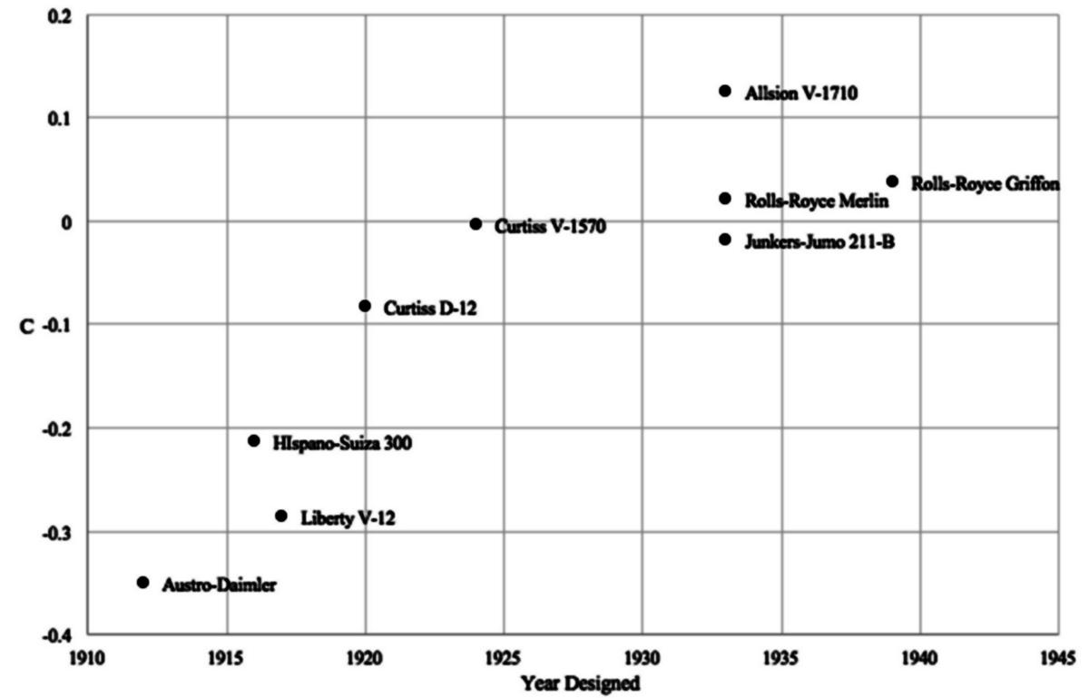
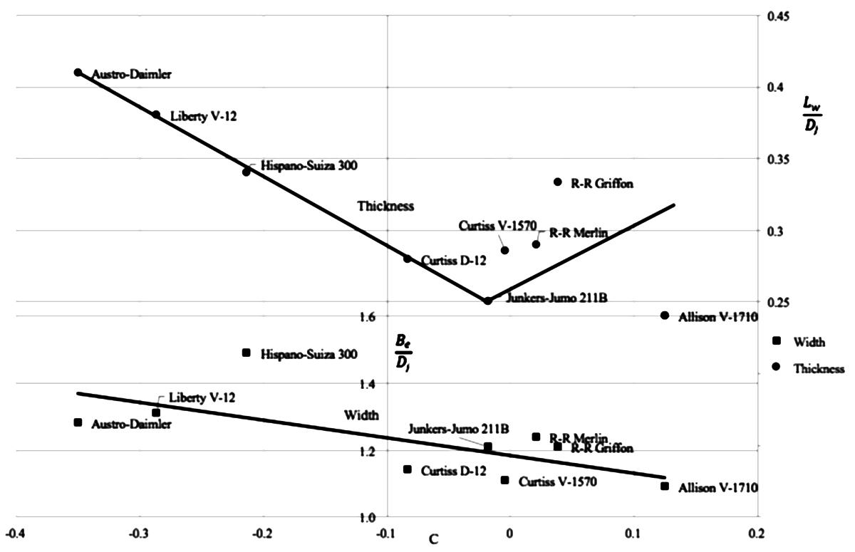
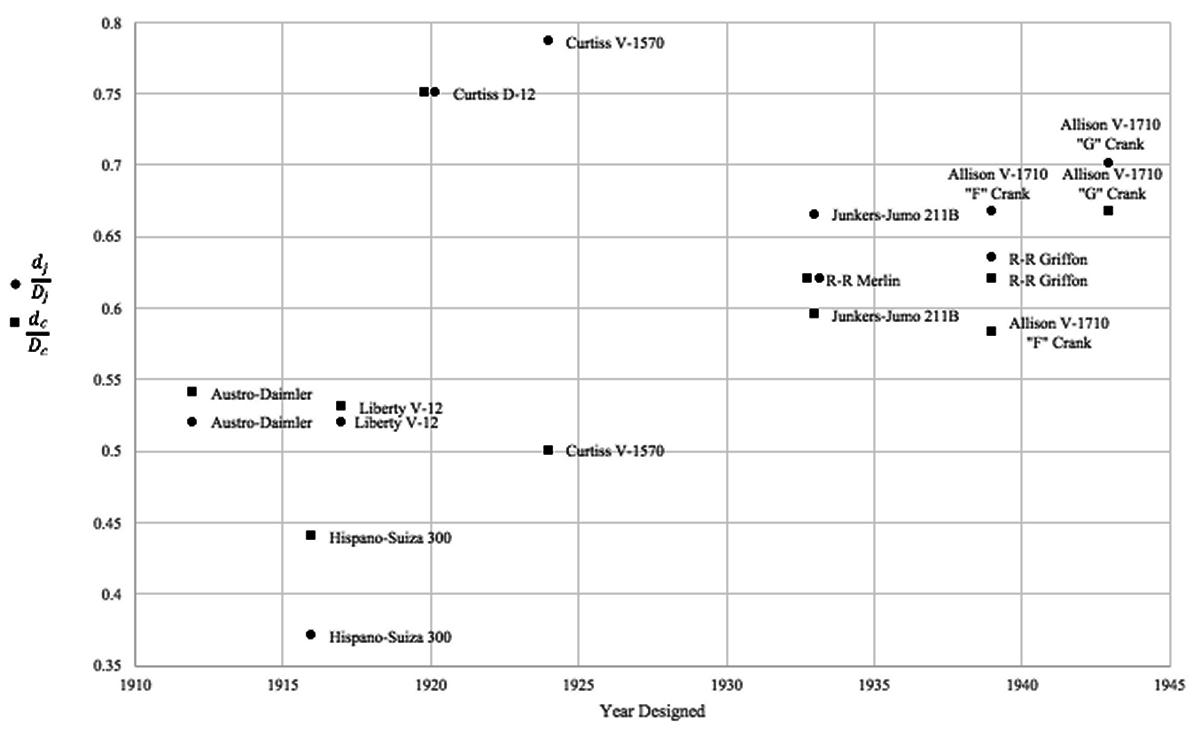
At this point it is important to introduce the idea of overlap between pin and journal in crankshaft design. Figure 7 defines the various symbols used here and defines dimensionless overlap, C. Figure 8 shows fatigue strength in bending versus dimensionless overlap. All of the cranks in the fatigue tests of Figure 5 had the same (negative) values of C so the effect of overlap is not shown in that figure. Figure 9 shows how overlap varied with time for a number of engines. None of these engines had a bore/stroke ratio greater than one. The Chrysler IV-2220 had a bore/stroke ratio of 1.1 and a dimensionless overlap of 0.19, greater than any of the engines in Figure 9. |
It seems intuitively obvious that, as the crankpin journal and the main bearing journal come closer together and eventually overlap, the crank web becomes less important as a load carrying member. Figure 10 confirms this observation as the dimensionless thickness of the web declines almost linearly as the overlap becomes less negative and then demonstrates more scatter as the overlap becomes positive. The width of the web shows much more scatter but also has a negative trend with an increase in overlap. The methods of analysis available at the time would explain this trend but the designer would not have been able to predict its effect on fatigue strength. |
 |
 |
 |
 |
| Fig. 7. Crank Element Nomenclature | Fig. 8. Ratio of Fatigue Strength in Bending at Zero Overlap versus Dimensionless Overlap (from Ref. 11) | Fig. 9. Crankpin and Journal Dimensionless Overlap versus Time for Various Engines | Fig. 10. Dimensionless Web Thickness and Web Width versus Crankpin/Main Journal Overlap (see Fig. 7) |
Holes and Fillets
|
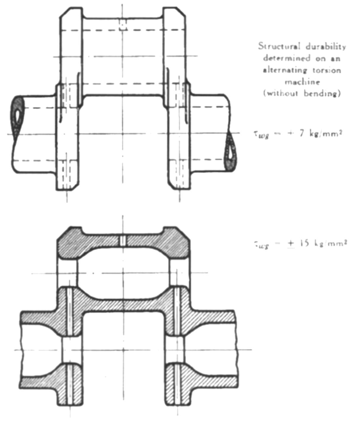
The usual failure mode in a crankshaft is a fatigue crack occurring at a stress riser. Most often its location is at a fillet between a journal or crankpin and the crank web, at the edge of the bored hole in the crankpin and web shoulder, or at the oil hole in the crankpin. The importance of as large a fillet as possible is illustrated in Figure 11. It is clear from this figure that a generous fillet that would let the fatigue strength approach 50% of the maximum was not possible with acceptable crankshaft length. All of the engines shown here were in the range of 30% to 41% of the maximum. The configuration used here as shown in Figure 11 gives a maximum fatigue strength of about 80% of that of a simple stepped shaft with the same fillet radius between the two diameters. The engine with the largest fillets, the Jumo 211-B, used undercut fillets that were not completely circumferential (see Figure 20) on both the crankpin and main journals. The undercut fillets are located at the points of maximum stress and minimum bearing load and have a larger radius than the conventional fillets that complete the circumference. Chrysler (10) examined undercut fillets using photoelastic techniques and concluded that there was no advantage to that approach but it isn’t clear how the comparison was made. It would seem that undercutting the fillet into the web rather than the journal would allow a larger radius without reducing the bearing area but apparently was never tried, possibly due to the difficulty of grinding and polishing the fillet. |
The other principal stress riser, the oil hole, also received considerable attention. Figure 12 shows a crank element from Reference 10 that is loaded statically in bending and torsion. The maximum stress is well below the surface of the journal and represents a stress concentration factor of 3.6. The area around the mouth of the hole was very highly polished to remove any potential stress risers such as scratches. Chrysler also carried out a photoelastic investigation into the inclination of the oil hole and found that from a radial hole to one inclined at 25° the stress concentration factor did not increase but increased rapidly at higher angles of inclination. The inclination of the hole in Figure 12 is about 35°. The type of oil delivery system typically used in the later engines did not utilize an inclined hole to the journal surface because the oil was delivered to the crankpin bore, which was plugged, and from there to the surface of the crankpin. The hole was typically at 90° to the plane of the pin and at the neutral plane in bending. This arrangement also allowed the pin bore to collect sludge through centrifugal action and prevent it from moving into the bearing. |
 |
 |
| Fig. 11. Relative Torsional Fatigue Strength versus Ratio of Crank Fillet Radius to Journal Diameter (from Ref. 9) | Fig. 12. Stress Distribution Around Crankpin Oil Hole (from Ref. 10) |
Pin and Journal Bores
|
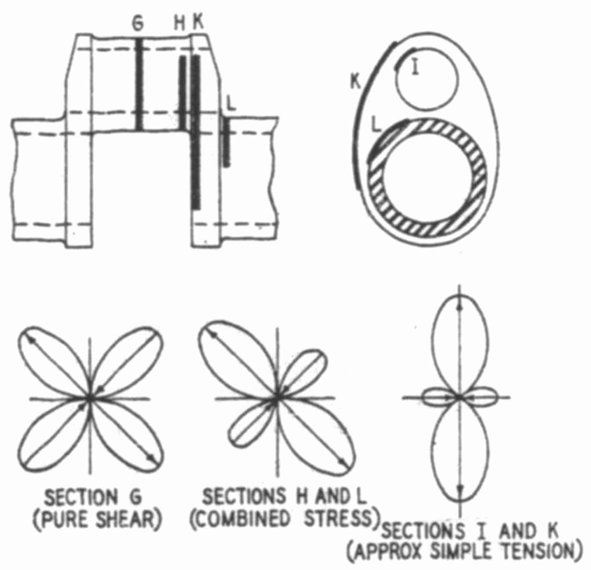
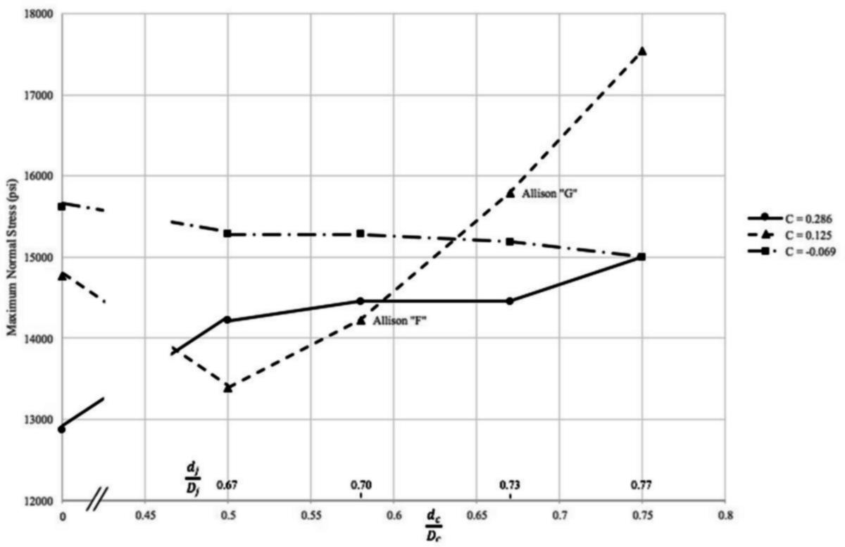
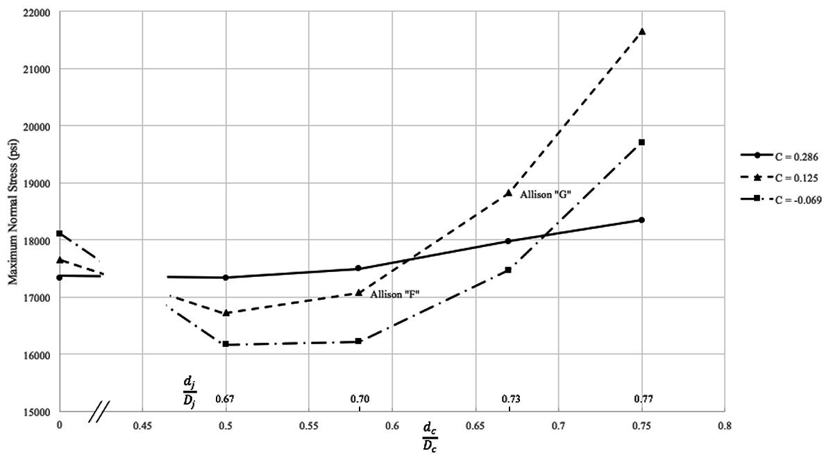
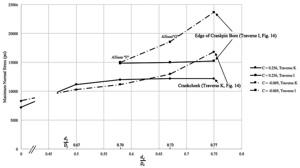
We have seen in Figure 5 that boring the pin and main journals gave an almost 2 to 1 improvement in fatigue strength in torsion (configurations A and B) and that tapering the bores into the web (configuration D) gave an additional 65% improvement. This knowledge was put to use in the design of the Jumo crank which can be seen from Figure 13 taken from Reference 11. This figure shows a more than two to one improvement in torsional fatigue strength versus about 1.7 in Figure 5. Presumably other design changes were made to get the added improvement. Comparing Figure 13 with the actual Jumo design (Figure 20) leaves little doubt that this is the aircraft engine shaft referred to in Figure 13. Only one other manufacturer is on record as having considered barrel pin bores. Chrysler looked at them for the IV-2220 and concluded that they gave only a 10% improvement in stress for the same shaft weight and were not worth the added complication in machining. The relatively small improvement may have been due to the very large overlap of the IV-2220 shaft as compared to the Jumo shaft. It seems intuitive that, as more of the load is carried through the pin and journal that the web bore becomes less critical. Figure 5 has shown the benefit of boring the main and crank pin journals. The question naturally arises as to what are the optimum diameters for these bored holes in terms of stress and weight. Of all the aircraft engine manufacturers of which I am aware, Allison appears to have carried out the most extensive evaluation of this question in the course of developing the “G” model of itsV-1710 engine. The work was carried out at the General Motors Research Lab using single crank elements loaded statically in bending and torsion (12). The location of regions of high strain was determined with brittle coatings and then strain was measured with the photoelectric extensometers developed by GM. Figure 14 shows the areas where strain measurements were made as indicated by the letters. Typical strain rosettes are shown for torsional loading. Figures 15, 16 and 17 show how the bore dimensions affected stress in bending and torsion. The effect of overlap (C) is also shown and, in the case of bending (Figure15), indicates why, with the proper choice of pin and journal bore sizes, larger overlap gave higher fatigue strength. It should also be noted that the advantage of lower torsional stress in boring the pin and main journal disappears with the 0.286 overlap, Figure 16, an effect not shown in Figure 5 where the overlap is significantly negative. Comparing these figures with Figure 8 it should be kept in mind that Figure 8 is a fatigue test and Figures 15, 16, and17 are measured stresses and also that the range of dimensionless overlap is much less in Figure 8. Note that GM carried out these tests varying both the bores in the pin and the journal in five stages simultaneously hence I have plotted the stress versus the two dimensionless ratios of these bores shown on the abscissa of these figures. |
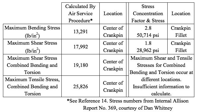
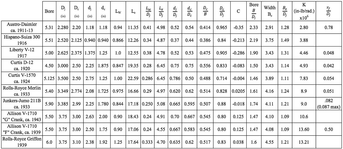
A plot similar to Figure 15 but representing the journal fillet stress rather than the crankpin fillet stress would, for the largest overlap, show lower stress at higher values of pin and journal bore sizes than for smaller values of overlap. The larger bore sizes required that a smaller diameter be left in the web so as not to interfere with the outer diameters of the pin and journal. The GM engineers appear to have believed this explained the Jumo barrel pin bore design but it isn’t clear to me what the two designs have to do with each other since the Jumo crank overlap was negative and boring straight through would not have interfered with the crankpin and main journal diameters (see Figure 20). The Allison V-1710 overlap remained at 0.125 for the “G” model crankshaft. The applied stress for bending and torsion are shown on the figures for the “F” and “G” Allison cranks. Note that in Figure 17 only two overlaps were tested, one larger (0.286) and one smaller (-0.069) than that of the Allison crank. It would seem reasonable to assume that the values for the Allison “G” crank fall between the two values shown for “Traverse I”. This Figure points out the very important point that stress in the pin bore or crank cheek can exceed that in the crank fillets when these bores become large. This series of tests allowed the Allison engineers to calculate stress concentration factors at the critical points just mentioned and incorporate them into their conventional analyses as discussed earlier. They still could not allow for the way in which the crankshaft and crankcase deflections changed the way in which the crank was supported. Table 1 shows a sample of the procedure just mentioned for the Allison V-1710 at 1,500 brake horsepower and 3,000 RPM. The first column in the table represents the results of calculations performed according to the technique described in Reference 8 where stress concentrations are ignored and simplifying assumptions are made regarding bearing supports. These numbers are for the center of the crankpin. The stress concentration factors are from the work reported in Reference 12 and discussed above. Since the stresses at the fillets are different from the stress at the center of the crankpin, the stresses listed are not the product of the stresses in the first column multiplied by the stress concentration factors. Since the location of the maximum shear and tensile stresses in the fillets are not the same, there is insufficient information to calculate maximum shear and tensile stresses. Figure 18 shows how the pin and journal bores, represented as ratios, changed over time for nine engines. The Curtiss engines, in particular the D-12, would appear to be somewhat ahead of their time regarding crankpin and journal bore sizes but they were not operating at the piston speeds and BMEP of the later engines. One wonders if the much smaller ratio of crankpin bore to pin diameter for the V-1570 was the result of some negative experience with the D-12 crankshaft. |
 |
 |
 |
| Fig. 13. Improvements in an Existing Aircraft Engine Shaft by Applying the Results of Tests Referred to in Fig. 5 (from Ref. 11) | Fig. 14. Location of Torsional Strain Traverses, and Typical Strain Rosettes (from Ref. 12) | Fig. 15. Maximum Normal Crankpin Fillet Stress in Bending versus Ratio of Pin Bore to Crankpin Diameter for Three Values of Crank Overlap Ratio (Applied Bending Load = 335 ft-lb, from data in Ref. 12) |
 |
 |
 |
| Fig. 16. Normal Crankpin Fillet Stress in Torsion versus Pin Bore to Crankpin Diameter for Three Values of Crank Overlap Ratio (Applied Torque = 2,000 ft-lb, from data in Ref. 12) |
Fig. 17. Maximum Crankcheek and Pin Bore Normal Stresses in Torsion versus Pin Bore to Pin Diameter Ratio (Applied Torque = 2,000 ft-lb, from date in Ref. 12) |
Fig. 18. Crankshaft Journal Bore to Journal Diameter and Pin Bore to Pin Diameter Ratios versus Time, Various Engines |
 |
Crankshaft Stiffness
|
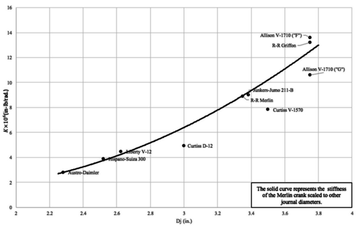
In order to see how the evolution in crankshaft design had affected the stiffness I calculated the stiffness of the various cranks analyzed in this study. I used a method developed by the British Internal Combustion Engine Research Institute (BICERI) as described in Reference 13. Of the 20 or so methods outlined, their approach gave the best agreement with data I have for the Rolls-Royce Merlin and the Liberty 12. Figure 19 gives the stiffness of a single crank element versus the main journal diameter. Note that the solid line is not a curve fit to the data points. It represents the Merlin’s crank scaled to the other diameters. Theoretically the stiffness of geometrically similar cranks should go as the cube of the scaling dimension, in this case I have used the journal diameter. Given the broad variation in design over the period 1912-1939 (see Figure 20) it’s remarkable how close all of the cranks are to the cubic scaling factor. Note that the engines that fall furthest from the curve are the ones with the larger bores in the main and crankpin journals as indicated in Figure 18. I have found no evidence that would indicate that Allison actually measured the stiffness of the V-1710 crankshaft. In an internal Allison report dated January 1, 1944, the stiffness of the crank was calculated using a method published by H. Constant in 1929. |
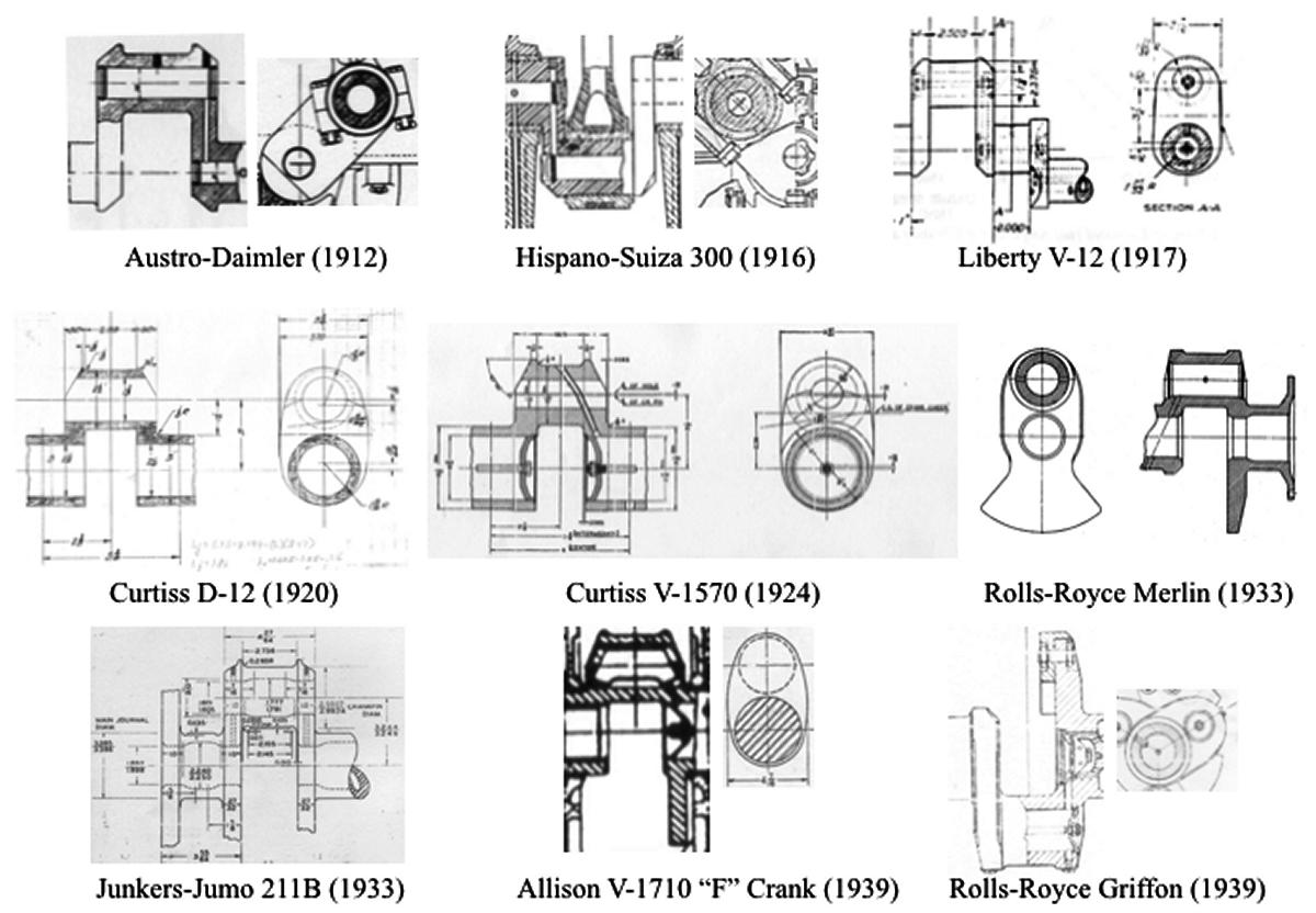
Figure 20 shows the various crank elements used to calculate the stiffness. Some, such as the Curtiss V-1570 and the Jumo, came from sources where they were essentially fully dimensioned and the remainder were scaled from knowing the stroke and journal diameters to get web and other dimensions. Of the cranks analyzed here, only the two Curtiss engines had open crankpins with a pressed-in tube to get oil from the main journal to the crankpin bearing. This results in the hole being 90° from the neutral plane in bending and at an angle which increases the stress concentration factor versus a radial hole. |
 |
 |
| Fig. 19. Single Crank Element Stiffness versus Main Bearing Diameter (Various Engines, ca. 1912 – 1943) |
Fig. 20. Selected Crank Throw Details |
Fabrication and Materials
|
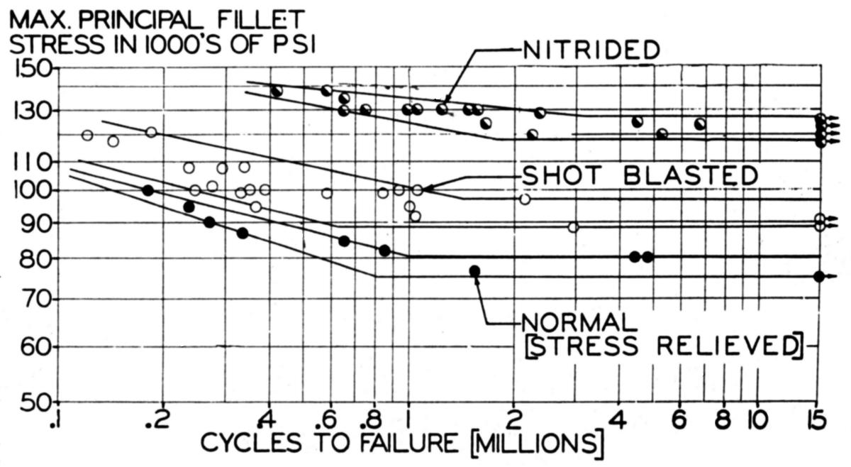
All of the crankshafts discussed here were forgings made from hardenable steels with small amounts of nickel, chromium and molybdenum. An excellent account of the fabrication procedure can be found in reference 15 describing the processing of the Merlin crankshaft at Packard in 1944. The Merlin crank weighed 250 pounds as forged and 104 pounds after final machining. Heat treating involved a 3 hour cycle for normalizing, quench and temper, two stress relief cycles of 4 hours each and 84 hours in the nitriding furnace. There were test coupons attached to the rough forgings which went through all of the heat treat cycles and were used to make test specimens for tensile tests and impact tests. By 1944 Packard was carrying out this procedure on one of ten crankshafts down from every shaft at the beginning of their experience with the Merlin. In order to improve the endurance limit in fatigue of the shaft two methods were adopted. Both accomplished this by inducing high compressive residual stresses which acted to counteract the tensile stresses due to bending and torsion. The first was shot peening adopted by Allison in early 1941 (16) and replaced by nitriding in late 1941. Figure 21 shows the effects of these surface treatments on the endurance limit for the Allison crankshaft. |
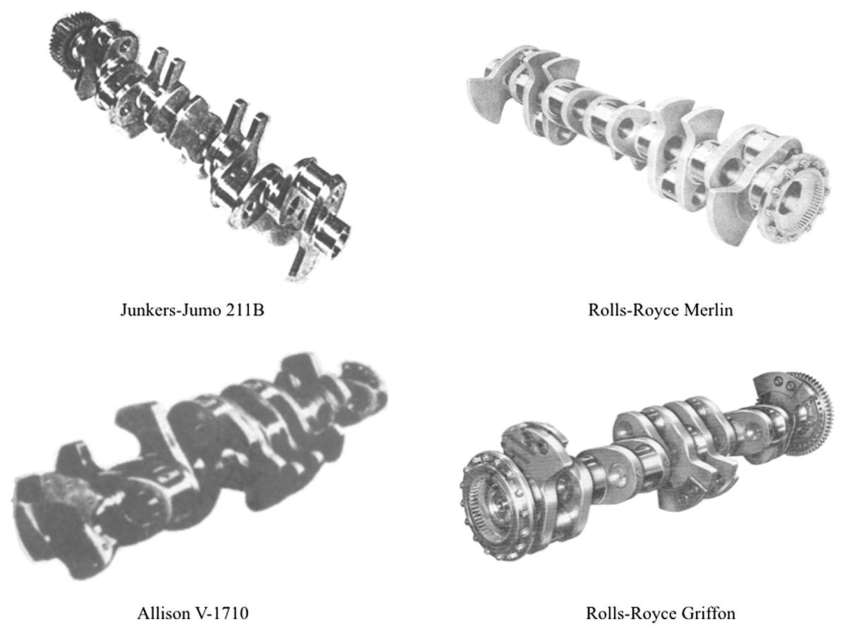
The increase in fatigue strength from about 75,000 psi to 120,000 was probably essential to get the much higher ratings from the Rolls-Royce and Allison engines that came later in the war. I have no information as to whether the Daimler-Benz 601 or Junkers-Jumo ever adopted this technique. Inspections of these engines carried out by American firms early in WW2 do not indicate that they had either of these surface treatments at that time. Figure 22 shows four late model crankshafts. Note that the Jumo crankshaft utilized 12 skewed counterweights on every crank-throw like the later Allison “G” crank. The bolted on counterweights of the Griffon appear to be somewhat skewed relative to the crankpin axis as well. The 6 and 8 counterweights of the Allison and Merlin were part of the crankshaft forging. The 12 counterweight Allison had the ten intermediate counterweights welded to the crank during processing. Figure 22 indicates that the flanges on both ends of the Allison crank were not symmetrical presumably to get additional counter-weight effect. I don’t know if the Jumo weights were attached and, if so, how that was accomplished. The Daimler 601’s counterweights were riveted in place and, given the similarities in their design, perhaps the Jumo’s were as well. |
Conclusions
|
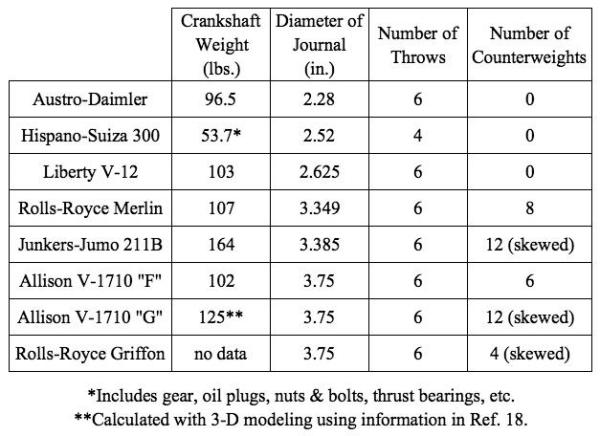
Table 2 gives the weights of crankshafts I have been able to find or estimate using a 3-D CAD model. In general the weights are bare crankshafts except for the Hispano engine as noted in the Table. I am quite sure the Merlin and Allison cranks are bare weights but unsure of the Junkers shaft. The Junkers shaft did not include the reduction gear which would have made the biggest difference, 16 pounds. Of the crankshafts analyzed in this report the Allison “G” would appear to be, neglecting the weight of the counter-weights, the most efficient in terms of weight per unit of journal size (see Table 2). Despite the larger main and crankpin journals compared to the Merlin, the V-1710 six counterweight crankshaft was about 4 pounds lighter than the Merlin’s. Examination of Figures 10 and 18 indicate why this is so. In Figure 10 the dimensionless web thickness and width are significantly lower for the Allison and the dimensionless pin bore to pin diameter and journal bore to journal diameter are greater as shown in Figure 18. Again, the degree of counter weighting obviously enters into this discussion of relative weights of the shafts since the Merlin had 8 versus 6 for the Allison. The Allison, having larger journal and pin diameters, was stiffer in bending than the Merlin which may be why it only needed 6 counterweights until Allison decided to rate the engine at 3,400 RPM at take-off in 1944, at about the time work started on the 12 counterweight crankshaft. This gets us back to the issue of crankcase stiffness discussed earlier regarding the inter-relationship between crankshaft and crankcase design and the fact that given a very stiff crankcase counter-weights can, as in the case of the Napier Sabre, become unnecessary. The weight of the Allison “G” crank given in Table 2 was calculated. I’m fairly confident in the 125 lb figure because, while the weight was not reported in Reference 18, the polar moment of inertia was measured and checked quite well with the value of the polar moment of inertia calculated by the 3-D modeling program. |
Figure 23 shows the effect of counter-weighting on the bending moment applied to the crankcase. For the 125 lb shaft with skewed counterweights the bending moment is reduced by about 14% at 3000 rpm and about 19% at 3500 rpm. The crankshaft listed as 41309 in Figure 23 had 6 counterweights according to Reference 14. I’m not sure of the configuration of the shaft numbered 43900 but it might have been an early 12 counterweight design without skewed counterweights since it is shown on the non-skewed curve. It’s unfortunate that we cannot reproduce Figure 23 for some of the other engines, particularly the Jumo 211-B and the Rolls-Royce Griffon. The Jumo crank is quite heavy for the size of its main journal and some of this is due to the relatively smaller bores in the journals and crankpins but some is due to the counterweights and, unfortunately, I had no way of analyzing them. The analysis of the “G” crank in Table 2 showed that the 12 counterweights added about 50 lb to the weight of the crankshaft. I was also unable to find a weight of the Griffon shaft but am hoping that someone who has one will weigh it so that it can be added to Table 2 and discussed. Without further information I would say that the Allison “G” crank was the most advanced design of the group analyzed here. |
 |
 |
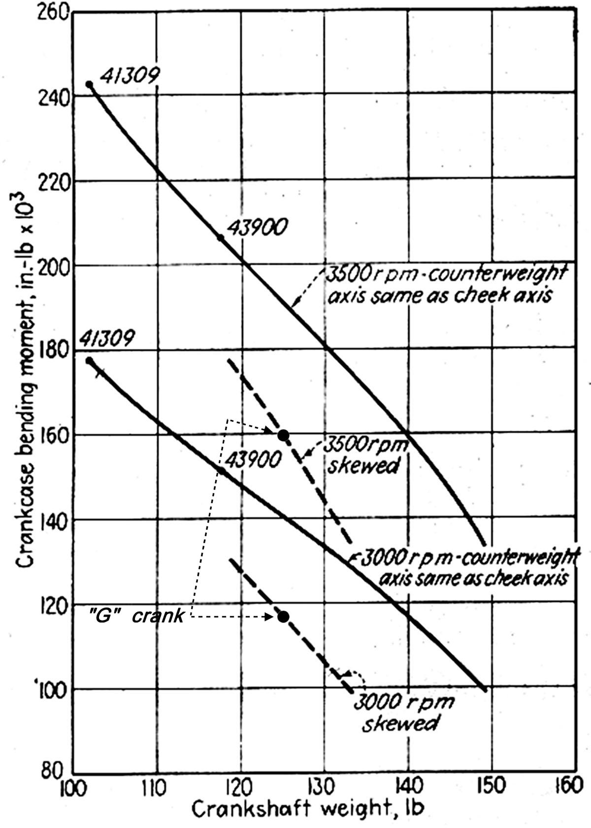 |
| Fig. 21. Effect of Surface Treatment on Endurance Limit (Bending, from Ref. 17) | Fig. 22. Typical Late Model Crankshafts | Fig. 23. Allison V-1710 Crankcase Bending Moment versus Crankshaft Weight (from Ref. 16) |
 |
 |
|
Acknowledgements The author wishes to thank Kim McCutcheon for his support and help finding sources of relevant material. Dan Whitney provided the internal Allison reports referenced in the text as well as advice and a review of the text. Dave Piggot of the Rolls-Royce Heritage Trust provided the information on the development of the Rolls-Royce Griffon engine. Conor Rachlin assisted with the graphs and tables and carried out the 3-D modeling of the Allison “G” crankshaft. |
References
1. ”The Fairchild-Caminez Engine”, Automotive Industries, July 30, 1927, p.160. |
Send mail to
![]() with questions or comments about this web site.
with questions or comments about this web site.
![]()