
Light-Alloy Forging
Large-Scale Production for Aircraft by Chevrolet in the United States
| This article first appeared in the Volume 6, Number 63 (January, 1944) issue of Aircraft Production magazine, and is presented here through the kind permission of Flight International. Thanks also to Bruce Vander Mark for furnishing volumes of Aircraft Production for scanning. |
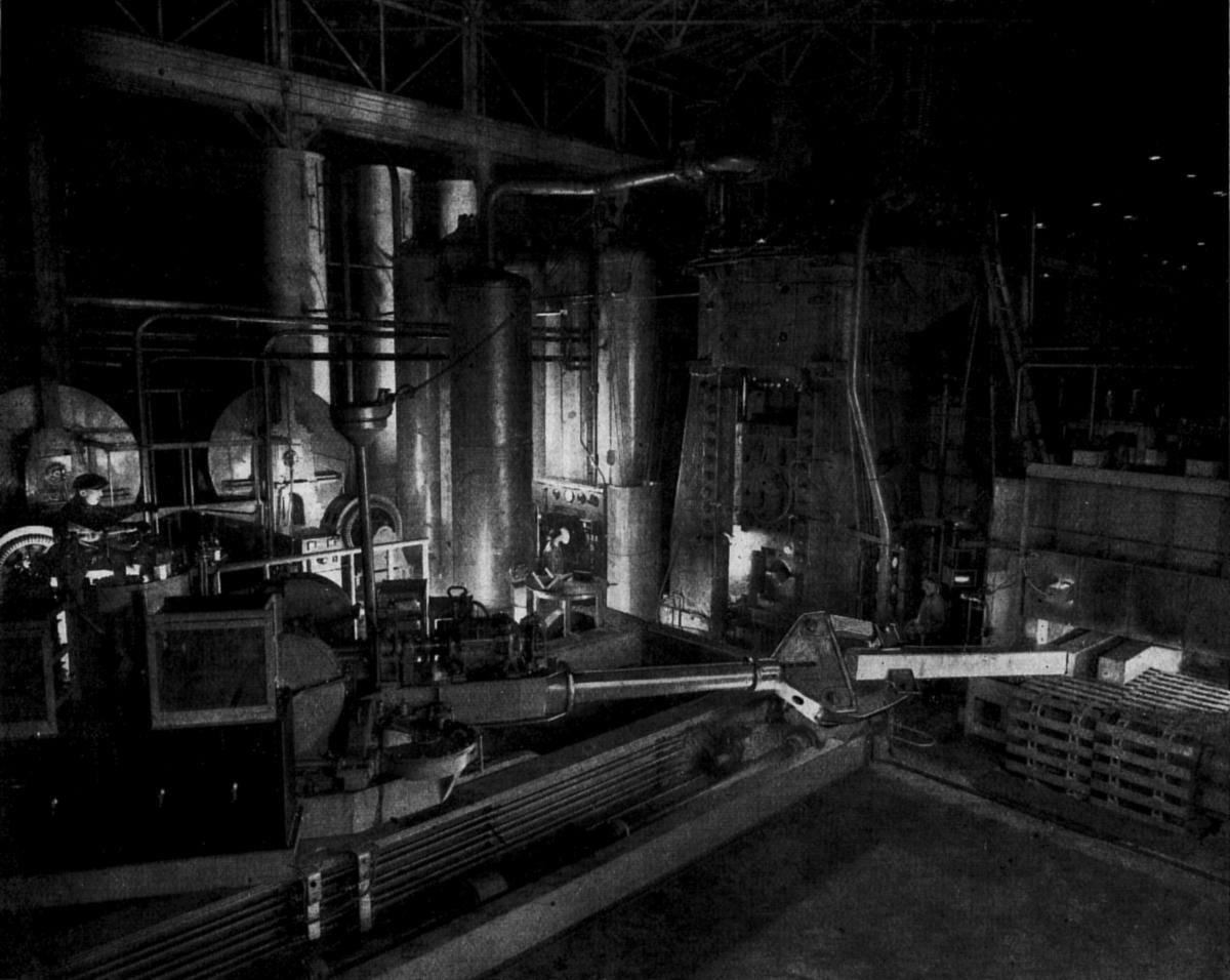 |
| Fig. 1. Large-scale equipment used in a plant of the Chevrolet Division of the General Motors Corporation for togging-down aluminium ingots to increase their tensile strength for the forging of aircraft-engine crankcase sections. Ingots heated in the furnace at the right are transferred by the claw-ended boom on the carrier-mounted turntable in the left foreground to the togging-down press in the centre background. This press exerts a pressure of 3,000 short tons and reduces the section of the ingot from 12” x 12” to 9” x 9”. To the left of the press is a bank of tanks containing air and water under a pressure of 4,500 psi for operating the hydraulic press. |
The Chevrolet Division of the General Motors Corporation now has four forging plants in operation producing light-alloy crankcase sections, pistons and many smaller parts for Pratt & Whitney engines manufactured in the Corporation's plant. Airscrew-blade forgings and other parts are also supplied to many makers of aircraft and engines. Peacetime experience gained in steel forging operations for an output of 1,000,000 motor vehicles per year was drawn upon in solving the problems encountered in the rapid quantity production of these forgings.
Some very large units of shop equipment were built, among them a 3,000-ton (short ton, i.e., 2,000 lb) hydraulic cogging-down press built by the R.D. Wood Co. and installed in the third plant, which began operations last December and is the largest of the three. This press reduces 1,500 lb aluminium ingots 9 feet long from 12” x 12” to 9” x 9” square section, thereby increasing the tensile strength from 40,000 to 55,000 psi. These are used for the forging of crankcase sections.
This press and manipulator-carrier that handles the ingots occupy an entire corner of the plant.
The press is set on a foundation 11 feet below floor level in a 20 x 25-foot chamber and rises nearly 30 feet above the floor. The pressure of 4,500 psi exerted against the top of the ram piston to maintain a force of 3,000 short tons for the moment of the die stroke is stored in an accumulator bank of four air bottles and a tank containing water and compressed air.
Each of these tanks is 24 feet high and of 32” inside diameter, has a capacity of 900 U.S. gallons, and weighs 61,000 lb. The air containers have laminated walls 6” thick made of steel plates welded together, and have been tested at an internal pressure of 9,000 psi. Pressure is built up in the system by two 300 hp motors driving a pair of pumps that have a capacity of 200 gal/min each. Double extra-heavy piping conveys the hydraulic fluid solution of water and soluble oil to the press cylinder, and all pipe fittings were machined from forged steel blocks. Fairly constant fluid level is maintained in the air-and-water tank by continuous operation of the pumps. The high air compression required to maintain a pressure of 4,500 psi on the fluid raises the temperature of the fluid considerably, so it is circulated through a heat exchanger to cool it.
The remainder of this article is available only to AEHS Members. Please Login.
Send mail to
![]() with questions or comments about this web site.
with questions or comments about this web site.
This website depends on cookies to make it function. If you continue to browse, scroll, click or otherwise interact, you are providing implicit acknowledgement of and agreement to this.
Copyright © 2002-2025 Aircraft Engine Historical Society