
Electric Airscrews
Design and Operation, Factory Layout, Machining the Hub Barrel, Special Fixtures and
Set-ups for Smaller Components, Track Assembly of Blades and Airscrews
by J. A. Oates, A.M.I.E.I., M.Inst.Met.
|
This article first appeared in the Volume 4, Number 49 (November, 1942) issue of Aircraft Production magazine, and is presented here through the kind permission of Flight International. Thanks also to Bruce Vander Mark for furnishing volumes of Aircraft Production for scanning. The operation and manufacture of the new Rotol electrically operated airscrew are briefly described in this article, along with descriptions of the reorganised factory layout and new plan of inspection. The track system of blade and airscrew assembly has been extended to include the new type of airscrew. |
 |
 |
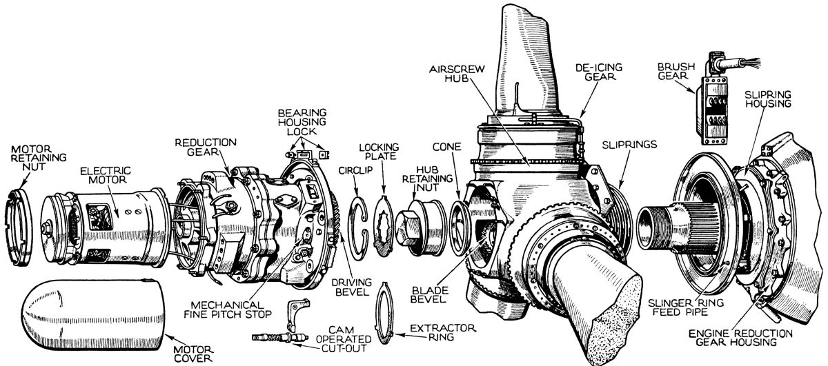 |
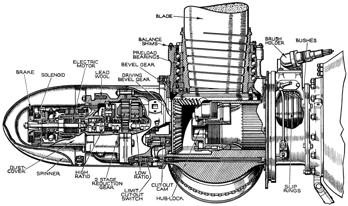
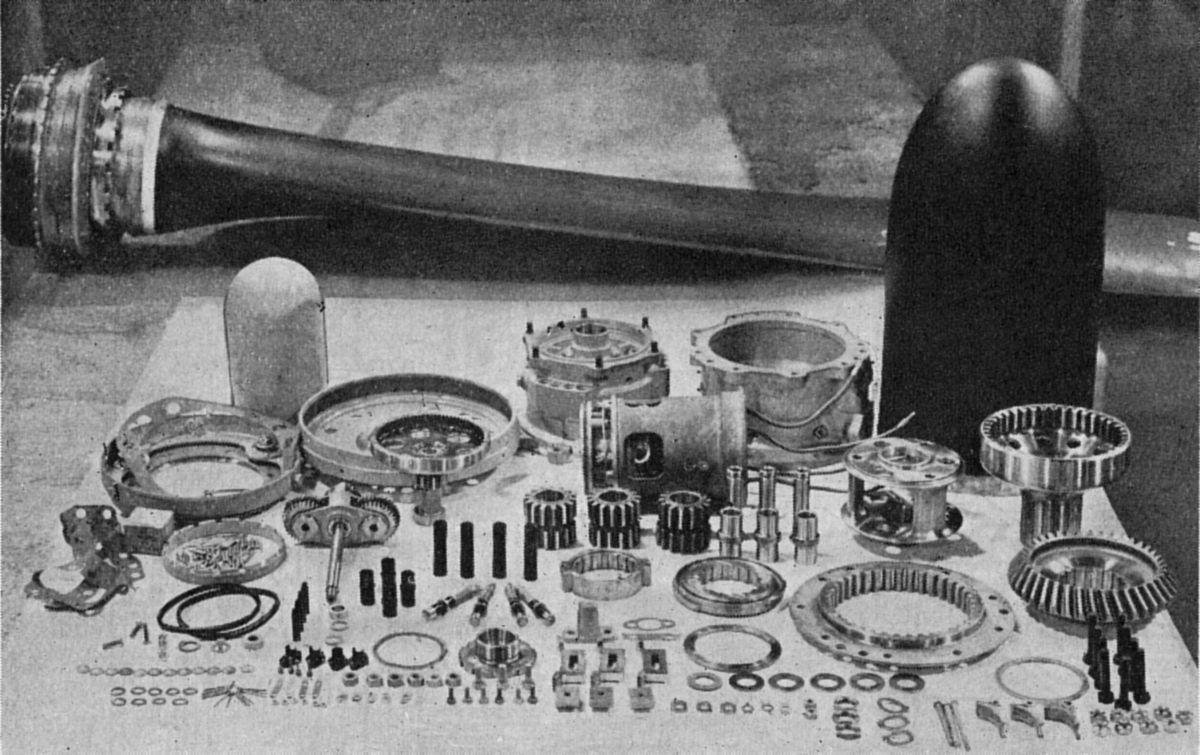
| Fig. 1. Cut-away view showing the internal mechanism of the Rotol electric airscrew. | Fig. 2. The component parts of a Rotol electric airscrew. | Fig. 3. An exploded view showing the separate airscrew components and the order of assembly. |
Progress in aircraft design is, to a certain extent, dependent upon the progress of airscrew design. To the range of hydraulically operated types a new Rotol electrically operated airscrew is now being produced for service. This new type may be operated as either a constant-speed airscrew with a wide pitch range or the pitch may be fixed at any desired point. Actuation is through the medium of automatically or manually controlled current flow.
This choice of operation increases the reliability of the airscrew, and the fixed-pitch feature enables a check to be kept on engine operation and ignition and mixture systems. Further, the ability to feather the blades adds to the security of flying, as it eliminates “windmilling“ when one engine is out of action.
Pitch changing is done through a power unit (Fig. 1) consisting of a 24-volt electric motor mounted on a reduction gear at the front end of the hub. The motor is driven direct from the aircraft batteries, and has two sets of field windings to enable reversible rotation. Its action is geared down by crypto-epicyclic reduction gearing to drive a master bevel gear which meshes with three bevel segments, one at the base of each blade adaptor, anti-clockwise rotation of the motor turning the blades to fine pitch and clockwise to coarse. Current passes through slip rings at the rear of the hub, and thence, by means of internal leads in the hub and reduction gear, to the motor. Three of the slip rings are for the coarse, fine and feathering circuits, and the fourth is the common negative.
At the front end of the motor is a brake lined with friction material and operated by a solenoid and springs, the forward face of the brake being attached to the motor armature shaft and rotating with it. When the circuit to the motor is closed, the solenoid becomes energised and holds the rear face away against the springs. With the circuit open and the solenoid inoperative, the brake is engaged and the motor and master bevel held. Overrunning of the motor and creeping of the blades are thus prevented.
The remainder of this article is available only to AEHS Members. Please Login.
Send mail to
![]() with questions or comments about this web site.
with questions or comments about this web site.
This website depends on cookies to make it function. If you continue to browse, scroll, click or otherwise interact, you are providing implicit acknowledgement of and agreement to this.
Copyright © 2002-2025 Aircraft Engine Historical Society