Bristol Superchargers
| This feature was excerpted from Superchargers as Applied to Bristol Aero Engines, published in 1943. Thanks to Bruce Vander Mark for scanning and the use of this material. The full manual, in color and high resolution, is available from Mach One Manuals |
Atmosphere
When dealing with the subject of superchargers, it is necessary to understand a few basic facts about the atmosphere. The term is applied to the comparatively thin layer of air surrounding the earth that varies in thickness between 7 and 10 miles according to the latitude. The chief physical properties of the atmosphere are pressure, temperature and density each of which is explained in the following paragraphs. All three may vary from day to day and consequently it is necessary to set a standard on which to base calculations.
Pressure
At sea level, the pressure exerted by the atmosphere at a standard temperature is 14.7 psi. That is, each square inch of the earth's surface supports a column of air about 10 miles high and weighing 14.7 lb. Atmospheric pressure is usually measured in inches or millimetres of mercury (Hg). One inch of mercury = 2.035 lb; therefore, 29.92 in, or 760 mm. of mercury = 14.7 psi absolute. A new standard unit of pressure was introduced however in 1914, and although it is not in general use in connection with supercharging, gauges are sometimes graduated with these measurements in addition to psi. This unit is called the “bar” and is defined as a pressure of one million dynes per cm³; the millibar equals 1/1,000th part of a bar, and is abbreviated to mb. One thousand mb represents roughly the pressure of the atmosphere at sea level, and to facilitate the conversion of inches Hg. into mb, it can be remembered that 1,000 mb are equivalent to 29.53 inHg.
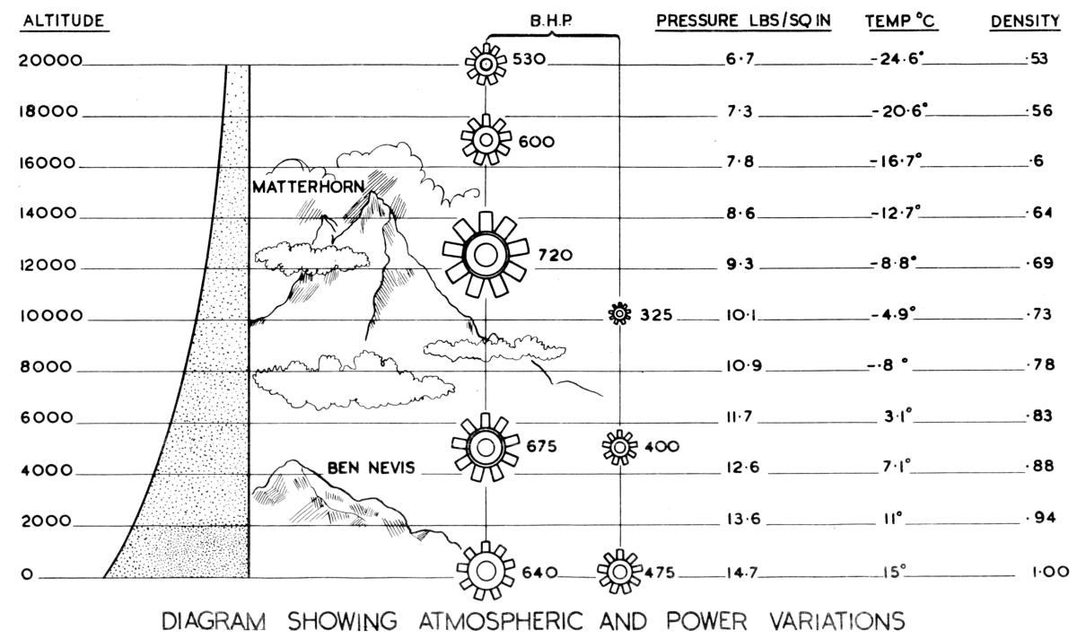
Since a column of air about 10 miles high and 1 inch square weighs 14.7 lb. it follows that a shorter column weighs less; consequently at the top of a mountain 5,000 feet high, the weight is reduced about 3 lb and is only 11.7 lb. The first important point, therefore, is that the atmospheric pressure on a surface varies according to the amount of air above it or in other words that pressure is reduced with height.
Temperature
The temperature of the atmosphere also falls with increase in height, but unlike pressure, the fall in temperature follows no definite rule, owing to up-currents and other variable factors there is no uniform drop with increase in height. Since however, an accepted standard of temperature is very necessary for aeronautical purposes, this has been established by the International Commission for Air Navigation. By this rule, which is known as the ICAN law, it is assumed that at sea level at latitude 45°, the temperature of the atmosphere is 15°C, and that up to 36,000 ft, there is a uniform rate of decrease with height of 1.98°C, per 1,000 ft. Above this altitude, the temperature is assumed to be constant at -56°C. These temperatures are not necessarily accurate for all conditions, but they represent a standard upon which to base calculations and are satisfactory for the purpose to which they are applied.
Density
Pressure and temperature both affect density and they are so related that if the temperature remains constant and the pressure is increased, the density also increases. If the pressure is maintained constant, an increase in temperature results in a decrease of density. But although both pressure and temperature are reduced with altitude, the net result is a drop in density, and density is progressively reduced with increase in height. Further variations occur from day to day owing to the varying conditions of pressure and density. It is therefore necessary to have a standard of density for reference and this, under standard conditions of pressure and temperature at sea level (i.e., 14.7 psi and 15°C, is given as 0.0765 lb per ft³. In other words, approximately 13 ft³ weigh 1 lb. The relationship of density at altitude to standard at sea level is known as the Relative Density and is obtained by dividing the density at altitude by the density at sea level. Figure 1 shows the relative values for various heights.
Definitions of International Atmosphere:
Standard Pressure = The pressure exerted by a column of mercury 760 mm (29.92 in) in height and given as 1013.2 mb or 14.7 lb.
Standard Temperature = +15°C at mean sea level at latitude 45°. Temperature varies with height at the rate of 1.98°C per 1,000 ft, up to 36,000 ft above which it remains constant, at -56°C.
Standard Weight = 1.226 kg. per m³ or 0.0765 lb per ft³ at sea level.
The Effects of Altitude
The power developed by an engine is dependent on the weight of the mixture that is burnt in the cylinders. As the piston moves down the cylinder it creates a depression (suction), and when the inlet valve opens, the charge that enters the cylinders is dependent on the pressure in the induction system that, in the case of an unsupercharged engine is governed by the pressure of the atmosphere and the amount of throttle opening. When such an engine is running at full throttle the pressure in the induction system is nearly that of the surrounding atmosphere. Consequently the higher an aircraft climbs the less is the weight of the charge entering the cylinders of its engine, since the pressure and the weight of the atmosphere both decrease with height, and the power output is reduced proportionately. An example of this is shown in Figure 1. An unsupercharged Jupiter engine that developed 475 bhp at sea level developed only 100 bhp at 5,000 ft at the same rpm and thus 75 bhp were lost for a gain of only 5,000 ft in altitude, whilst at 10,000 ft the power output was only a little over 300 bhp.
The reduction in air density at altitude means that the resistance offered to the flight of an aeroplane is less at height than at sea level, but although it is therefore possible for the aeroplane to fly faster, the power decreases more rapidly than the resistance to flight. In order to utilize the possibilities of increased speed at altitude and to be able to operate aircraft at greater heights it is necessary to devise a means of maintaining the power with gain in altitude. This has been achieved by the incorporation of the supercharger.
The supercharger is an engine-driven fan that on Bristol engines is interposed between the carburetter and the induction system. The fan, or impeller, as it is called is driven from the crankshaft through a train of gears that impart to it a high rotational speed.
Now where there is rotation, centrifugal force acts radially outwards from the axis of rotation. This force is universal and acts on solids, liquids and gases. Imagine that the supercharger starts from rest. The air contained in the impeller passages or between its vanes is forced to rotate with it and by the action of centrifugal force each particle of air is thrust outwards towards the periphery of the impeller. Owing to this motion a suction or region of low pressure is produced at the eye of the impeller, and air or mixture flows into the impeller through the carburetter and air intake and leave the impeller at a high velocity with an imparted energy in the form of kinetic energy. Before the mixture enters the induction system it passes through tke passages of the diffuser vane ring and the diffuser converts the kinetic energy to pressure energy at low velocity. In order to understand this matter fully, it should be realized that in the impeller work is done on the mixture at the expense of certain power, but once it has left the impeller the gas contains an amount of energy, which the diffuser converts from one form to another.
Two facts emerge from the preceding statements. The first is that driving the supercharger requires a certain amount of power and that this power must be taken from the engine. Neglecting frictional losses, all the power transmitted from the cylinders of an unsupercharged engine to its crankshaft (gross bhp) is delivered to the propeller, except for the negligible amount used to drive accessories. But when a supercharger is added the gross bhp must be divided between the supercharger and the propeller; the higher the power required to drive the supercharger, the less is available for the propeller. It follows, therefore, that for comparable engines a somewhat higher induction pressure (greater weight of mixture) is required for a supercharged than an unsupercharged engine to obtain the same power output (propeller bhp) at sea level. But whereas the power of the unsupercharged engine falls off soon after the aircraft begins to climb that of the supercharged type can be maintained up to a height limited only by the capacity of the supercharger. This fact is shown diagrammatically in Figures 1 and 2. Since the power is dependent on the weight of mixture entering the cylinders, it will be seen that power can be increased by raising the pressure delivered by the supercharger above that required merely to restore the loss due to reduction in density at altitude. To increase the pressure and weight of the mixture delivered to the engine the speed of the supercharger must be increased and more power is required to drive it. This has a marked effect on operating conditions and will be referred to in the section dealing with that subject.
The second point is that if a supercharger is designed to maintain a given pressure up to a height of say 10,000 ft, the impeller must be driven at a high speed owing to the considerable reduction in atmospheric pressure at that height. But such a supercharger, if permitted would give far too much pressure at sea level, and high boost pressure may cause failure owing to the high BMEP causing mechanical breakdown, or the high temperatures and pressures may result in detonation, which is a most undesirable condition. Consequently at sea level the pressure delivery must be restricted to give only the required power, and this is achieved by closing the throttle butterflies and limiting the amount of mixture entering the supercharger. As altitude is gained the butterflies are opened progressively, thereby admitting more mixture to maintain the original pressure delivered by the supercharger until a height is reached at which they are fully open; this is known as rated altitude. By this means, the pressure delivery of the supercharger is kept at a constant figure, but if the climb is continued further, the supercharger can no longer maintain the induction pressure and the power begins to fall off. In the present-day engines the induction or boost pressure is controlled automatically and the method is described in a later chapter. The pressure in the induction system is indicated by a gauge known as the boost gauge and the dial of the instrument used on British engines is graduated in psi above or below the zero mark. Zero is indicated thus "0" and the gauge is calibrated so that when it is subjected to a pressure equal to that of a standard atmosphere, i.e. 29.92 inHg or 14.7 psi the needle registers at "0".
|
|
| Fig. 1 | Fig. 2 |
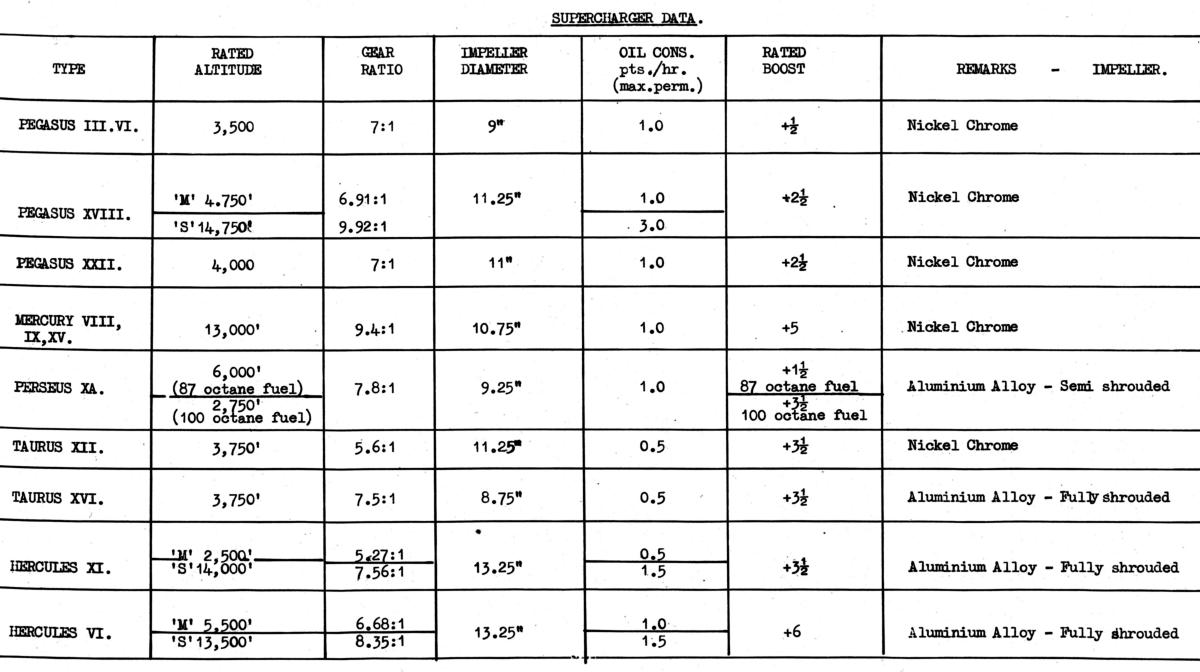 |
| Table 1. Bristol Supercharger Characteristics |
To complete this introduction to the subject of superchargers, a third important point must be dealt with. We have already learned that both pressure and temperature affect density. The pressure of the mixture entering the engine is raised by passing it through an impeller that is driven at a high speed and in this process the temperature of the gas is raised considerably. The temperature is affected by several factors such as the ratio of fuel to air and the amount of heat taken from the air to evaporate the fuel. But basically it is dependent on the impeller speed and varies roughly as the square of this speed; thus the higher the engine speed, the greater is the temperature rise. Now since the induction pressure is kept constant and the temperature is raised, the result is a drop in density and consequently a reduction in the weight of mixture delivered to the cylinders. As an illustration of this a Hercules engine running at sea level 2,400 rpm and +2 psi boost, develops about 1,020 gross bhp when the supercharger is driven at 6.5 times crankshaft speed. If, however the engine is fitted with a supercharger driven at 8.5 times engine speed and run under the same conditions, the gross bhp is only approx 958. This reduction in the power transmitted to the crankshaft is due to the loss in mixture weight caused by the higher temperature of the charge.
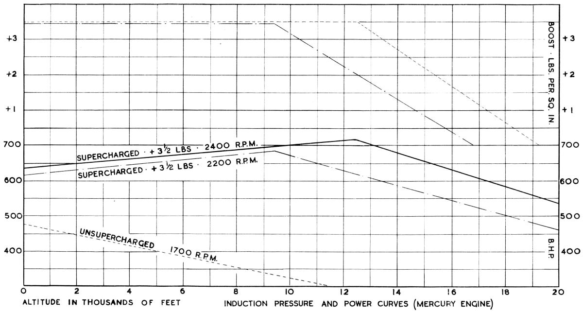
As an aircraft climbs and the temperature of the atmosphere drops, the air entering the supercharger at the lower temperature results in a lower delivery temperature and the density is correspondingly increased. Thus, the higher an aircraft climbs, up to rated altitude the greater the power output of its engine for the same induction pressure. The curves of Figure 2 indicate the power and induction pressure of a Mercury engine as altitude is increased. At sea level, at a boost pressure of +3.5 psi and 2,400 rpm, the power is 635 bhp. The boost pressure is kept constant up to a height of 12,250 ft, but the power rises until it reaches 718 bhp This is largely because of the increase in the weight of mixture due to the lower temperature at altitude.
There is another factor that assists in the increase of power with altitude. Whilst the engine is running at sea level it exhausts into an atmospheric pressure of 14.7 psi, but at altitude the less dense atmosphere results in improved scavenging of the cylinders and a consequent increase in the charge entering the engine.
Definitions
A. The primary function of the supercharger is to increase the density of the induction mixture by maintaining an induction pressure up to a predetermined height.
B. This height is known as the rated altitude.
C. The pressure that the supercharger can deliver at the rated altitude and at normal rpm is known as the rated boost.
D. The rpm at which the rated boost is obtained is known as the international rpm.
E. After the gas has passed through the supercharger, the increase in its temperature due to the speed of the impeller results in a reduction of volumetric efficiency and consequently of power output.
F. This loss is reduced at altitude owing to a cooler charge.
G. The loss of atmospheric density at altitude results in a reduction of back pressure on the exhaust system, thereby improving the scavenging of the cylinders and increasing the volumetric efficiency of the engine.
Control of Boost Pressure in Early Mercury and Pegasus Engines
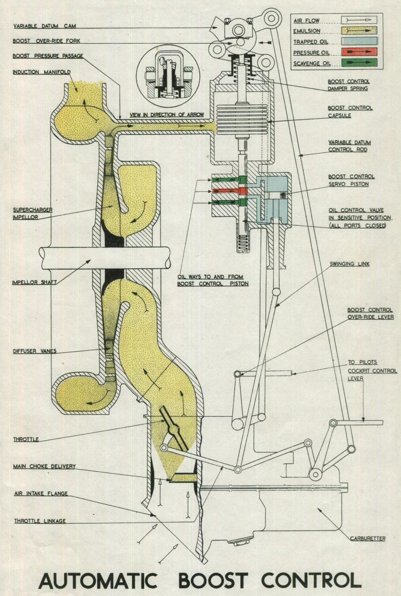
In general all superchargers that are positively driven are capable of delivery pressures higher than those normally required at sea level and low altitudes. Consequently, the delivery is controlled by partially closing the throttle butterflies and limiting the quantity of mixture entering the supercharger. On modern engines, this is achieved automatically by the boost control unit, which consists of a small chamber that is open only to the pressure in the induction system and containing an aneroid capsule with a sliding valve attached to its lower end. The capsule, which is sensitive to the pressures in the induction system, expands or contracts with variation in pressures. Since the capsule is held at its upper end variations in length caused by different induction pressures cause the sliding valve to be raised or lowered in its guide. As this occurs, oil under pressure is admitted to a servo motor, thereby causing its piston to move down or up. This movement is transmitted to the throttle butterflies by suitable linkage, which consists of two rods, one from the throttle butterflies and the other connected to the pilot's lever on the carburetter layshaft. Both are connected to the piston rod by a swinging link (see Fig. 3). The valve is provided with “lands” by means of which it directs oil from the engine system to either side of the servo motor piston at the same time permitting the exit to the scavenge system of the oil on the opposite side of the piston. Pressure oil is fed to the space between the centre lands. If the valve is raised, the ports leading to the cylinder are uncovered; pressure oil is admitted above the piston and the oil beneath passes out of the lower port and so to the sump. The effect is reversed when the valve is lowered.
When an engine is stationary, the pressure in the induction system is the same as that of the atmosphere but when the engine is started, it falls to some negative figure. The capsule reacts by expanding, thereby lowering the valve and directing oil beneath the servo-piston that moves to the top of its stroke. Subsequent throttle opening is accompanied by an increase in induction pressure that reaches a figure that will compress the aneroid to a degree where the valve is raised sufficiently to re-direct oil above the piston. Consequently, the piston commences to move down the cylinder, closing the butterflies and reducing the pressure. As soon as it begins to fall below that at which the control is set to govern, the aneroid again expands. Thus the capsule and valve will take up an equilibrium position where the lands just cover the ports and the servo-piston will be in some intermediate position in the cylinder. When climbing, the tendency for the induction pressure to fall is counteracted by the action of the boost control until a height is reached where the butterflies are fully open. This is the rated altitude for the specific pressure. Above this height the control is inoperative but if rpm are caused to rise, as in a dive, the boost control will intervene and close the butterflies the amount required to control the pressure.
The position of the capsule in its chamber governs the pressure required to compress it to a length where the valve is in the equilibrium position. If the capsule unit is lowered bodily, that pressure will be increased; conversely, if it is raised the pressure will be less. Here then is a means of setting the control to govern at any desired pressure and to obtain progressive increase in pressure as the throttle lever is moved through its range.
The cam by which this action is obtained is known as the "variable datum cam". The basic setting is by means of the screwed upper end of the capsule unit spindle, and is made with the throttle lever in the fully open position. Proportional pressure at intermediate throttle settings is obtained by means of the cam situated at the top of the control unit; the profile is designed to reset the control progressively as the throttle lever is opened, the highest point on the profile giving rated boost pressure. Oscillation of the valve that would cause surging of the boost pressure is eliminated by the incorporation of a light damper-spring beneath the valve.
During slow running, the servo-piston is always at the top of its cylinder, but soon after the throttle lever begins to open, it begins to move downwards, thereby adjusting the butterflies to control at the pressure set by the capsule under the influence of the cam. By this means, rated boost pressure can be obtained only when the throttle lever is fully open. Any intermediate setting will result in a proportional boost pressure, which the boost control maintains to the full rated altitude for that particular setting. The throttle lever therefore becomes a boost selection lever; its position controls the power output up to rated height and its movement ensures a steady rise or fall of power.
In this design consideration is given to two important factors:
(a) Should the aneroid capsule be punctured, the capsule will expand and the servo valve move to permit oil to flow to the piston that will open the throttle butterflies to the maximum. When this occurs the boost control unit is automatically cut out and the pilot has direct control over the engine.
(b) A minimum power stop is provided so that in the event of a puncture in the oil supply the pilot is assured of a certain predetermined power by moving tie throttle to the fully open position.
 |
 |
| Fig. 3 | Fig. 4 |
Temporary Power for Take-Off
For a short period such as take-off, 15% to 20% increased power can be taken from the engine, provided that additional fuel is supplied to prevent detonation. Since the boost control has been set to prevent the induction pressure from exceeding a safe degree with normal fuel consumption, it has to be compelled to give a larger throttle opening for take-off. This adjustment is known as "over-riding the boost control", and is made mechanically. A forked lever fitted to the control enables the pilot to depress the whole boost capsule assembly an additional amount sufficient to give the predetermined take-off boost. The operating linkage is also connected to the carburetter where it opens a jet to give the extra fuel required to prevent detonation. Since the whole movement of the throttle lever is employed to operate the variable datum cam the override fork is connected with the mixture control lever, which is moved backwards through a gate to depress the aneroid. Once the take-off has been accomplished, the lever is returned to the normal position when the enrichment jet and the override device are cut out of action.
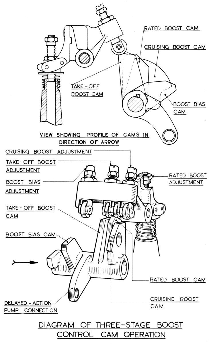
The logical development of this unit to eliminate the external linkage, was to incorporate it in the carburetter body, on the later types of engines therefore, the boost control unit is an integral part of the carburetter. The fundamental principle, i.e. the aneroid capsule pack with the servo valve and piston are similar but a number of improvements were made possible by this change the most important being the introduction of the three stage variable datum cam that eliminates the necessity for the override device and permits the setting of the Maximum Economical, Rated and Take-off boost at a definite angular movement of the pilot's control. Cam action is transmitted to the aneroid assembly, through the medium of a tappet block (Fig. 4), which is provided with an individual tappet for each cam, those for cruising and take-off being adjustable. As on the earlier type, the rated adjustment is on the aneroid spindle and forms the basic setting and the datum for the other two.
Boost Limiting Screw
From Figure 4 it will be seen that the boost-control cam pack incorporates a fourth cam. This is the boost reversal or boost bias cam and is necessary for the following reasons. Most modern aero-engines show a characteristic known as boost reversal, and it is necessary to understand how it is caused before appreciating the function of the boost limiting cam and its adjusting screw. The symptoms of boost reversal are as follows. As an engine is throttled down the induction pressure and the rpm will both decrease until a point is reached where further closing of the throttle lever will cause the rpm to fall but the induction pressure to rise. This is known as boost reversal. In order to follow the sequence of events it is necessary to consider the cycle of operations. Before the piston reaches the end of its travel on the firing stroke the exhaust ports open; since there is still a certain amount of pressure in the cylinder, the burnt gases begin to rush out of the exhaust port. The residue is expelled by the rising piston and at 1,000 rpm these gases attain a fairly high velocity in the exhaust pipe. The inlet valve opens at about 20° before top dead centre, at which point the pressure in the cylinder has fallen to approximately that of the atmosphere. At these rpm the induction pressure will be about 6 psi below that of the atmosphere. Since both inlet and exhaust valves are open at this stage there will be a tendency for gas to flow to the region of lowest pressure, that is, from the exhaust through the cylinder. The gas in the exhaust pipe however has a fairly high velocity in the opposite direction and before the reversal of flow can take place the gases must first be brought to rest and then accelerated towards the cylinder. This will take time, and the time will depend on the velocity of the exhaust gas when the inlet valve opens. If the velocity is such that the exhaust port closes before the reversal of exhaust gas flow occurs it will, of course never take place, and this state of affairs actually exists until the rpms fall to about 750. Below this speed the velocity of the exhaust gases becomes very low; and the inlet and exhaust valves are open together for a longer period. Hence there is time for the gases to flow from the exhaust system into the cylinder and even into the induction system. The slower the engine runs, the more time there is for this to occur. Therefore once the given minimum speed is reached the induction pressure will rise as the rpm are reduced.
From the description previously given of the operation of the boost control, it will have been learned that, as the throttle lever is closed, the position of the boost capsule assembly in its chamber is progressively changed, so that the unit controls the induction pressure throughout the range of throttle lever movement. Now let us consider the circumstances when boost reversal occurs. Below 750 rpm we have seen that in spite of continued closing of the throttle the boost pressure increases, although the boost control has been reset to govern at a lower figure. The rise in boost pressure compresses the capsule, thus raising the valve that then directs oil above the servo-piston in an attempt to close the throttle butterflies and correct the boost pressure to the figure at which the control is set. The more the butterflies close from this point the higher will be the induction pressure. Eventually the butterflies will be completely closed. If the throttle lever is now opened the engine will fail to respond and will continue running at a low speed until the throttle lever has reached a position where it resets the boost control to govern to a figure just above that of the pressure in the induction system.
The fitment of a boost limiting screw enables these conditions to be overcome by limiting the upward travel of the boost control capsule assembly in its chamber. This makes the throttle control completely mechanical below speeds of approximately 1,000 rpm. When throttling back therefore, the control is progressively reset and the length of the capsule increases. Below 1,000 rpm the boost limiting screw begins to compress the capsules, and the reaction of the servo-piston is to open the throttle butterflies. Before it can do this it reaches the limit of its travel and is held firmly thereby the oil pressure. Thus, any further closing of the butterflies can be achieved only by movement of the pilot's lever, and the control is then purely mechanical. The boost limiting screw is therefore set to render the boost control inoperative at an induction pressure a little higher than ever likely to be attained at slow-running. On some carburetters the boost limiting screw is situated on the tappet block and registers either against the carburetter body or the accelerator pump arm.
Throttle Lever Creep
Somewhat similar circumstances cause the phenomenon known as throttle lever creep (although this can also be caused by an entirely different circumstance). When an engine is shut doom, the depression in the induction system is immediately replaced by air at atmospheric pressure, which compresses the boost capsule and thus raises the valve. Accordingly the passage to the top of the servo piston is opened, but no movement of the piston occurs, since there is no pressure in the oil system. In general this is the position of the boost control unit during the period of idleness. When repeated attempts are made to start the engine the oil pressure will begin to build up, but, owing to the low rate of turning, the pressure in the induction system remains higher than that at which the boost control is set to govern at the small throttle lever opening. The capsule therefore remains compressed, and the oil flowing above the piston shuts the butterflies. As these reach the slow-running stops, the force of the oil pressure is transferred to the linkage; and since the butterflies can close no further the throttle-lever is forced forward. In some cases this lever cannot be moved in this manner and bending of the linkage results. The fitment and correct adjustment of a boost limiting screw eliminate this trouble.
The other cause of throttle lever creep is an accumulation of oil beneath the valve of the boost control capsule stack. When an engine comes to rest, atmospheric pressure compresses the capsule stack, which therefore lifts the valve. Some warm oil may seep to the cavity below the valve, and in extremely low temperatures this oil congeals. Consequently, when the engine is started, the congealed oil prevents the valve from moving downwards under the influence of the expanding capsule. The same sequence of events as for boost reversal then occurs. If, therefore, low temperatures are experienced or anticipated, the throttle lever should be moved slowly to the fully open position after the engine has been shut down. The lever should be left in this setting, in order to lower the capsule assembly and so prevent the accumulation of oil.
Two-Speed Supercharger
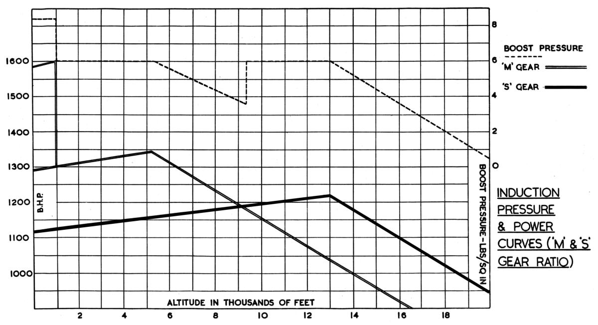
In order to maintain power to a high altitude it is necessary to drive the impeller at a high speed owing to the rarified atmosphere, therefore at any height below the rated altitude, the quantity of mixture that enters the supercharger must be limited, and the unit is working at less than maximum efficiency. That is, it is being driven at a speed higher than that necessary to give the pressure being used and is therefore absorbing power without giving a maximum return. It is definitely uneconomical to drive a supercharger faster than the speed at which it will give the required boost pressure. At sea level therefore such a supercharger, for reasons already given, will result in a considerable loss of power. The ideal supercharger would be one in which the speed could be varied to give just the boost required, but the manufacture of such a unit would present considerable difficulty. The result is a compromise, and a supercharger having two impeller speeds is now in general use. This type of unit provides ample power for operation at high altitudes and power with reasonable economy for take-off and lower level operations. The pilot may select the gear ratio that meets with his requirements, the "M" gear giving low or medium speed and the "S" gear high speed. Owing to the governing action of the boost control, both gear ratios give the same boost pressure, but in the case of “S” gear the boost is maintained to a greater altitude. But as will be shown in the next section incorrect selection can have a very great effect on performance.
Operating Conditions
There are three cockpit controls that affect supercharger operations:
1. The throttle lever position determines the boost pressure that is delivered by the supercharger and maintained constant up to the rated height by the boost control unit. It is a boost selection lever and in conjunction with the propeller control lever determines the power output of the engine. In addition its position largely controls the amount of fuel entering the engine and both power and enrichment jets are interconnected with it.
2. On propellers fitted to most engines the blade angle can, within limits, be adjusted by the pilot to increase or decrease speed, and the selected speed will be maintained by the action of the constant speed governor unit. The propeller control lever hence becomes in effect an engine speed control lever.
3. By means of the supercharger gear lever, the pilot can select high or low speed and it is very important to understand the effect of the two speeds on the power output of the engine. In either gear ratio, the boost pressure recorded on the gauge is identical and depends on the throttle lever position. But the power output of the engine is very different.
Assuming that the engine is running on the ground with the throttle lever in the take-off position and take-off rpm selected, a Hercules VI engine delivers 1,580 bhp to the propeller when "M" gear ratio is engaged. But if a change is made to "S" gear, the power drops to just under 1,300 bhp. The loss of approximately 280 bhp is caused by the two factors already mentioned; the higher impeller speed raises the mixture temperature thereby lowering its density and more power is absorbed in driving the supercharger at the increased speed. It is interesting to analyze this power loss. The power delivered to the crankshaft (gross bhp) is about 1,780 bhp when “M” gear is in engagement; changing to "S" gear causes a drop to approximately 1,580 bhp so that the lower density of the mixture due to the higher speed, reduces the power available from the cylinders by about 200 bhp The gross bhp must be divided between the supercharger and the propeller. Approximately 200 bhp is absorbed in driving the supercharger at take-off rpm in "M" gear leaving 1,580 bhp for the propeller. The higher speed in "S" gear absorbs an additional 80 bhp; consequently of the 1,580 bhp delivered to the crankshaft only 1,300 bhp is available for the propeller.
Obviously, "S" gear should never be used for take-off. The correct method of supercharger control during take-off and climb can be followed from Figure 5. With "M" gear ratio selected, take-off boost and rpm are maintained until a height of 1,000 ft is obtained when boost and rpm are reduced to maximum continuous cruising. This boost pressure will be maintained to about 5,500 ft but the power output will increase owing to the lower temperature of the mixture and the reduction in back pressure on the exhaust system. Continued climbing will cause both boost pressure and power to fall. From the diagram it will be seen that if the gear ratio is changed when the boost begins to fall, there will be a, very considerable loss in power. Nothing is gained by changing to "S" gear unless the attendant power output is at least equal to that given in "M" gear. This rule holds good whatever boost pressure is selected. From the curve, it can be seen that this condition will not arise until the boost pressure in "M" gear has fallen by at least 2 psi. At 9,000 ft the rising power line of "S" gear intersects that of "M" gear, and if the change is made at this height, the boost pressure is restored and the power output in "S" gear at +6 psi is the same as in "M" gear at the lower boost pressure. This pressure is maintained up to about 13,000 ft when it once again begins to diminish. It is important to observe that, although "S" gear is engaged, the power output is much lower than when "M" gear is giving the same boost pressures, and the engine has in fact a different set of ratings.
The preceding remarks can be summarized as follows:
1. It is unnecessary and uneconomical to use "S" gear if the required boost pressure can be obtained in "M".
2. The use of "S" gear reduces the gross bhp owing to the high temperature of the charge.
3. "S" gear setting reduces the power transmitted to the propeller by absorbing more power to drive the supercharger.
4. "S" gear should never be used unless it will give at least 2 psi more boost than "M" gear.
The propeller control lever has a marked effect on supercharger efficiency, for it will be remembered that the supercharger is geared to the engine crankshaft, and consequently changes in engine speed are reproduced in the supercharger.
 |
 |
| Fig. 5 | Fig. 6 |
Assuming that an aircraft is cruising at a certain indicated airspeed (IAS), a given engine power is necessary to maintain the speed, and this power may be obtained by a number of combinations of boost pressure and rpm The most economical way is to run the supercharger at a speed at which the butterflies will be opened fully in order to maintain the boost pressure. In these circumstances, the minimum power is required to drive the supercharger and the delivery is much cooler at the lower impeller speeds. The throttle lever should therefore be moved to a position just below the C.B. gate to make sure that the power jet is definitely out of action, and the rpm reduced until the desired IAS is obtained. It is possible that when the rpm have been reduced to the limit of comfortable flying, that the IAS is still too high. The throttle lever should then be closed to reduce power. Whilst the rule "High boost : Low rpm" holds good for all conditions, it should be realized that the low rpm gives a lower rated height. For instance, when the aircraft is cruised at just below +2 psi boost, which is the maximum boost pressure for economical cruising, and 1,900 rpm, which is low rpm, the pressure can be maintained only to 7,000 ft when in "M" gear. If it is desired to cruise at 10,000 ft the rpm must be increased to about 2,000 when the power is the same at the maximum boost obtainable at these rpm (i.e. 1 psi). Under these conditions, the supercharger is working at maximum efficiency, that is, doing maximum work for the power it is absorbing. "S" gear should never be used if the power required can be obtained in "M" gear. The pilot of course, does not know the power output of his engine, but he does know his boost and IAS, which amounts to the same, thing, and he should obtain the IAS at as high a boost and low rpm as possible. By this method, fuel and oil consumption are reduced and the engine is operating under the most favorable mechanical conditions.
 |
| Fig. 7 |
Single-Speed Supercharger Constructional Details
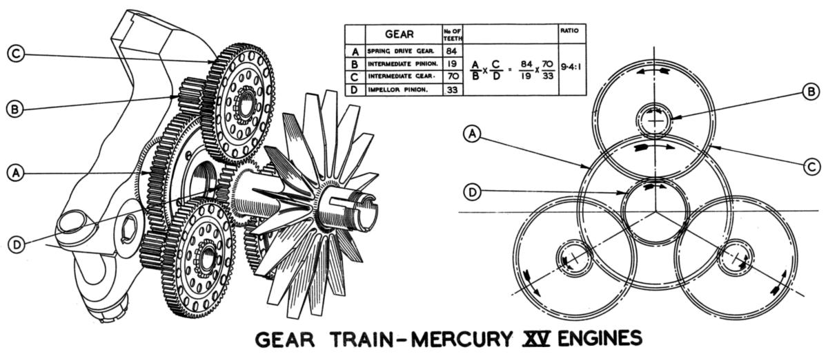
Most single-speed superchargers fitted to Bristol engines are basically similar, but since different aircraft require engines with different ratings, their impellers vary both in diameter and in the speed at which they are driven. It will therefore be sufficient to describe the supercharger fitted to a Mercury XV engine, which has a 10.75” impeller that is driven at 9.4 times engine speed. The supercharger unit, which is situated between the crankcase and the rear cover, consists of the supercharger casing, the volute casing, and the impeller assembly with its driving gears (Fig. 6). When the casings are assembled together as shown in Figure 7 they form the impeller chamber, the diffuser chamber and the induction chamber; the latter has its outlets tangentially inclined to assist the flow of gas to the cylinders. When the unit is assembled to the engine, the rear crankcase wall and the supercharger charger casing form a gear chamber, which is vented by three large breather holes in the crankcase. The purpose of a volute is to lead the mixture from the carburettor to the impeller in the direction of rotation, thereby reducing the impact shock of the air stream on the revolving blades. The impeller assembly consists of the impeller shaft, which is integral with its gear, an oil thrower, ball race and oil seal housing, the impeller, which is located on serrations, another oil seal housing and ball race, and a distance piece. The whole assembly is mounted on the two ball races, one being housed in the supercharger casing and one in the cover that closes the rear of the volute casing. When the individual components are properly secured together by the tabwasher and locknut, there should be no movement relative to the shaft. The impeller blade tips may revolve as rapidly as 1,370 feet per second and their speed can be appreciated by a comparison with sound that travels at 1,080 feet per second. Consequently, the impeller is subjected to high operational stresses, and it is therefore machined from a forging to minimize the possibility of material weakness. Owing, again to the high speed, a small error in balance would impose extremely high loadings on the impeller races, which are of the single-row type, and the whole impeller assembly is therefore balanced dynamically.
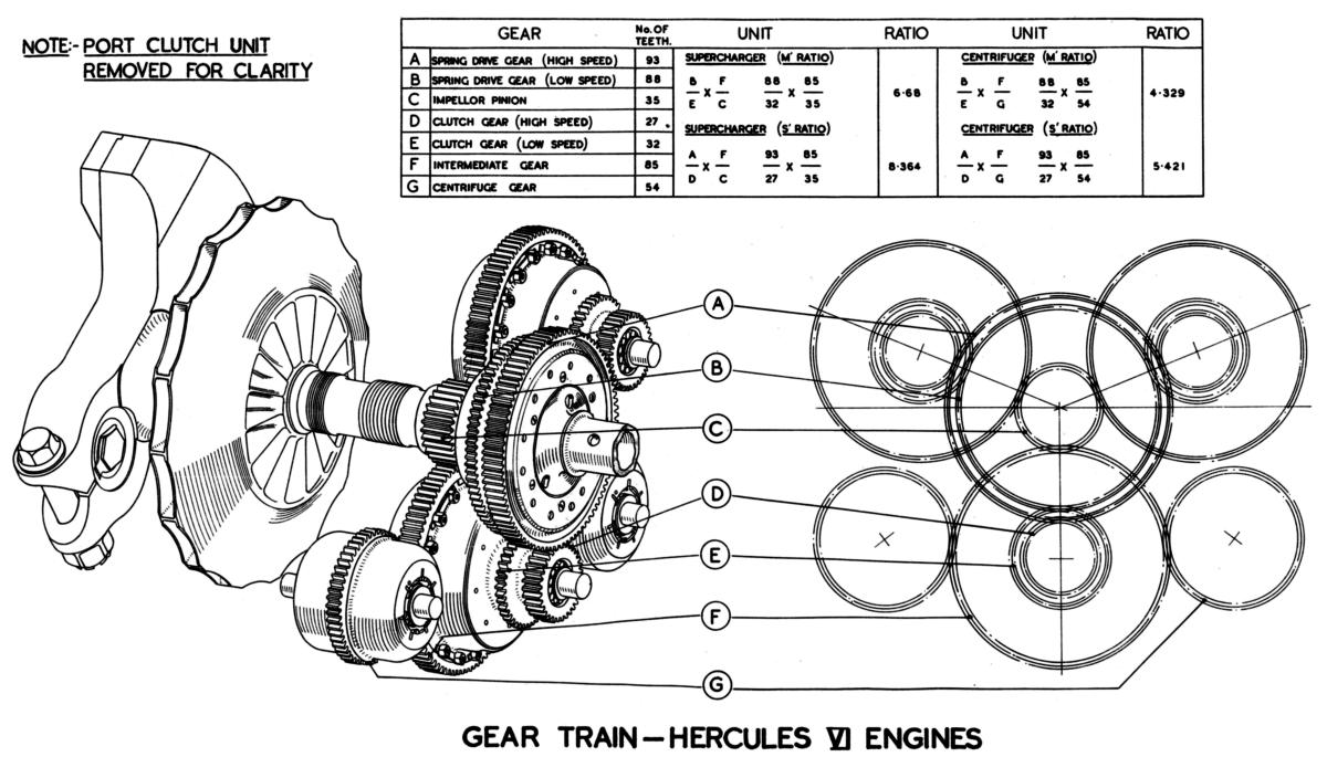
The operational cycle of the internal combustion engine subjects the crankshaft to recurrent impulses, and it is therefore advisable to damp out the resultant vibrations and impart a smooth driving torque to the teeth of the supercharger gear train. Consequently, the initial drive is through a spring-loaded gear, which, as shown in Figure 6 comprises a centre that is keyed to the crankshaft, and a gear-ring that is carried on two bronze side-plates. Interposed between the pawls of the centre and gear ring are six stiff springs provided with hardened steel end pads. In transmitting the driving torque from the centre to the gear-ring these springs absorb the cycle variations of the crankshaft and thereby protect the gear teeth. The spring drive gear meshes with the pinions of the three intermediate gears, which are mounted on spindles in the supercharger casing and held in position by a steel support ring. Considerable power must be transmitted to drive the impeller, and the intermediate gear is therefore triplicated to equalize the loading on the gears. Since the impeller is driven at such a high speed, abrupt changes in speed such as are caused by rapid acceleration or deceleration throw a considerable strain on the driving gears. For example, if an engine using an impeller with a gear ratio of 10:1 were rapidly accelerated from 1,000 to 2,000 rpm, the impeller would have to accelerate from 10,000 to 20,000 rpm in the same length of time. Such acceleration would not only require, considerable engine power, but might also cause damage to some part of the mechanism. For this reason the drive from the pinion to the intermediate gear is transmitted through a centrifugal clutch that permits a certain degree of slip when the speed is changed suddenly. As shown in Figure 6 a driving centre attached to the intermediate pinion has several bronze clutch blocks between its radial projections, whilst the intermediate gear is mounted on extensions on the driving centre. Thus the pinion, the driving centre and the clutch blocks can revolve independently of the gear. When sufficient speed is attained, the clutch blocks are thrown outwards by centrifugal force and they begin to transmit the drive from the pinion and centre to the gear. As the speed rises the amount of frictional grip increases until the drive is virtually solid, and no slip will occur unless the speed is altered suddenly. The three intermediate gears engage the impeller shaft pinion and thus the drive is taken from the crankshaft and the spring drive gear to the intermediate pinions, then through the centrifugal clutches to the intermediate gears and so to the impeller shaft. Figure 8 shows the gear train diagrammatically and indicates the relative speeds.
Two-speed Supercharger Construction Details
All Bristol two-row engines are fitted with down-draught carburetters and the intake ports are at the top of the supercharger casing. This design gives an uninterrupted stream of air to the intake and a gravitational flow of mixture to the impeller.
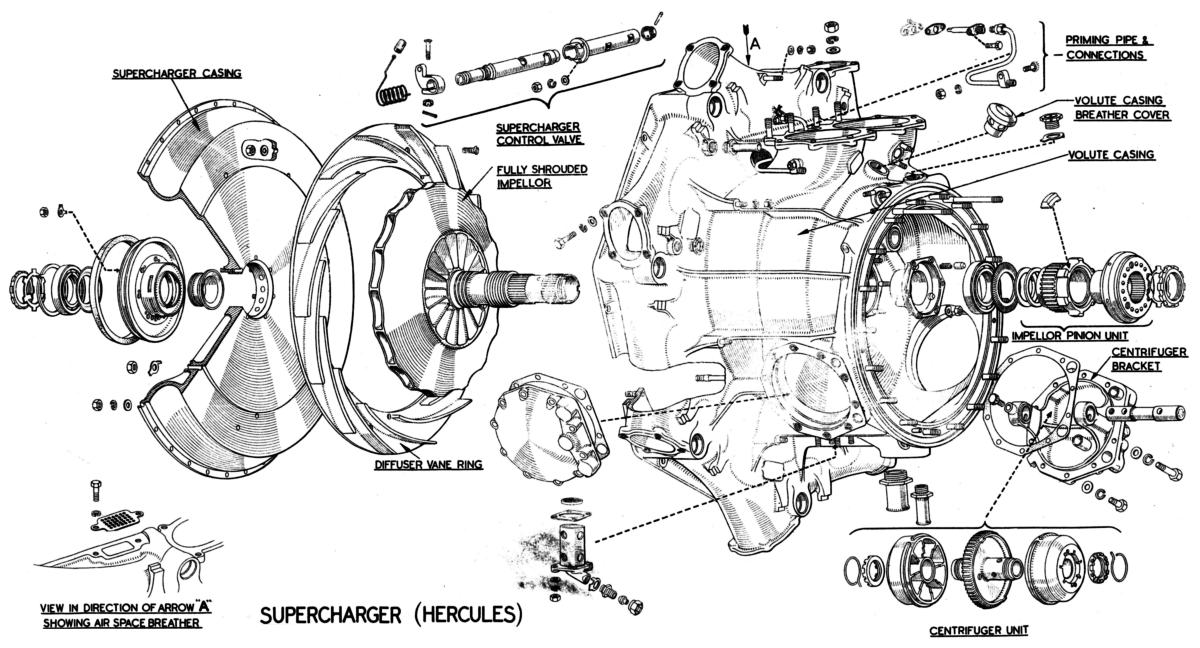
With the introduction of the two-speed supercharger, extensive structural alterations were necessary; these are shown in Figures 10 and 11. The volute casing, which constitutes the major portion of the supercharger unit, is extended rearwards to form the gear chamber, whilst the supercharger casing simply acts as a cover. In addition to carrying the front impeller race and the diffuser vane ring, this casing completes the impeller, diffuser and induction chambers when it is fitted to the volute casing.
 |
 |
| Fig. 8 | Fig. 10 |
 |
 |
| Fig. 11 | Fig. 12 |
On previous engines, carburetter flooding when the engine was stationary merely engendered a risk of fire. With a down-draught carburetter, however, it is also possible that neat fuel may enter the induction system and lower cylinders thereby washing away the lubricant and increasing the chance of hydraulic locking. Delubrication is particularly serious in sleeve-valve engines and to prevent this contingency the base of the volute casing incorporates a fuel drain, which permits free petrol to drain away from the aircraft. A gauze at the top of the fuel drain unit helps to prevent any fuel in the drain chamber from being ignited by a possible backfire when the engine is started. Since the drain is on the intake side of the supercharger, the carburetter is tuned to compensate for the amount of air that enters when the engine is running.
The serious effects of lubrication render certain precautions essential. If a continuous stream of petrol flows from the drain, the lower cylinders should be examined to ensure that the cylinders and pistons are adequately lubricated and the drain plugs should be removed from the three lowest induction pipes to drain them. The lower induction pipes of later engines incorporate a specially developed drain valve that opens automatically when the engine is stopped.
The impeller, which is machined from an aluminium-alloy forged billet, is of the fully shrouded type, and is shrunk onto the serrations of the impeller shaft The two components therefore, must be regarded as integral. The use of aluminium renders the assembly much lighter, thereby relieving the load on the bearings and gears and improving acceleration and deceleration characteristics. In addition, the general efficiency of the supercharger is improved, since the shrouding reduces the scrubbing action of the gases between the impeller and the supercharger casing, and virtually pipes the charge up to the diffuser chamber.
Whilst the removal of the gear chamber to the rear of the volute casing has enabled shorter induction pipes to be used it has necessitated a different method of assembly. The spring drive gear is positioned at the rear of the supercharger driving shaft, the gear centre being integral with the shaft, which is assembled to the engine after the supercharger is fitted. Serrations at the forward end of the driving shaft engage similar serrations in the crankshaft, end-location being provided by the forward face of the rear cover centre bearing and the rear-face of the spring-drive centre.
The spring drive gear embodies a two-ratio gear ring, which engages the high- and low- speed pinions of the intermediate gears. On the two-speed type of supercharger, the intermediate gear units incorporate hydraulic clutches to transmit the drive from either the high- or low- speed pinions, and the speed at which the intermediate gear revolves depends on the clutch that is engaged. From the intermediate gears, the drive is taken to the impeller shaft pinion, then through a centrifugal clutch to the impeller, the clutch housing being attached to the impeller shaft (see Fig. 12).
Two-speed superchargers employ only one centrifugal clutch unit, which is mounted on the impeller shaft, whilst the intermediate gears house the hydraulic instead of the centrifugal clutches. The impeller pinion meshes with the intermediate gears and is free to revolve on its shaft, the clutch blocks being located between dogs that are integral with an extension of the pinion. Centrifugal force throws the blocks into contact with the clutch housing, which is serrated to the impeller shaft, and the drive is thereby transmitted frictionally from the pinion to the shaft Since the impeller shaft that carries this clutch revolves at a much higher speed than the intermediate gears, the centrifugal force is greater and permits the use of only one clutch unit without reducing the efficiency of the drive.
Although hydraulic clutches are embodied in the intermediate gears they neither replace the centrifugal clutches nor perform their function. The sole purpose of the hydraulic clutches is to bring into operation the gear ratio required. Each intermediate gear is situated between a high-speed and a low-speed clutch, which are denoted "S" and "M" respectively, "S" clutch being located in front of the gear. Each clutch unit includes the pinions and the whole is free to revolve on a spindle that extends between the volute casing and its cover. The clutches are operated by pressure oil from the engine.
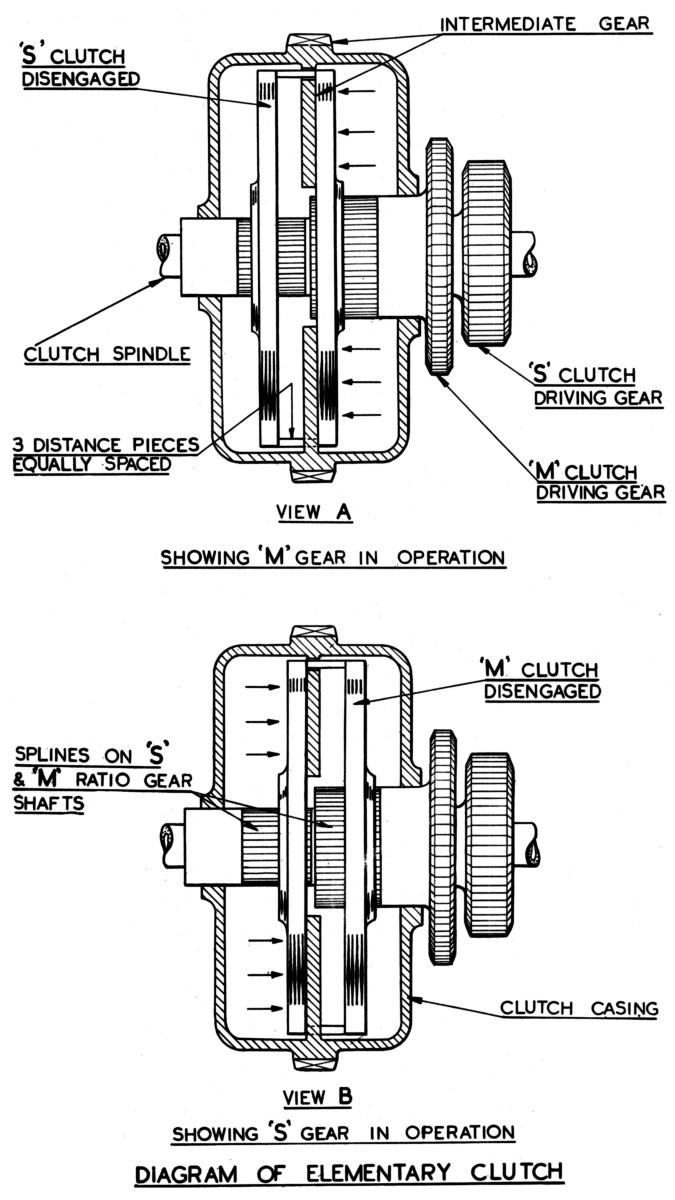
Figure 13 shows diagrammatically the basic principle on which the hydraulic clutch operates. The clutch driving members are splined to the shafts of their respective gears. When "M" gear is in operation as shown in sketch (a), the "M" clutch driving member transmits the drive to the intermediate gear and the "S" clutch driving member is disengaged and running free. When the gear is changed to "S" ratio, both driving members are moved quickly along their splines and the drive is then transmitted by the "S" member, the "M" member running free.
The construction of the actual clutch unit is more involved and the component parts are shown in Figure 11. Each unit consists of the driving shaft with its integral gear, two friction-lined driving plates splined to the shaft or its centre, and two driven plates splined to the housing. The housing is attached to the intermediate gear, whilst the shaft of the "S" gear revolves inside that of the "M" gear and projects through the intermediate gear into the "S" clutch unit. Both clutch units, together with the intermediate gear, are mounted on the clutch spindle. The outer driven plate is also a piston, and a sealing ring is therefore fitted on its outside diameter and in its bore to prevent the leakage of oil from behind it. To engage a clutch, oil under pressure from the engine system is directed behind this piston, moving it along its splines and pressing the plates together against the inner driving plate, which is rigidly secured to the shaft The oil pressure then forces the housing and intermediate gear in the opposite direction until the face of the gear is in contact with the friction-lined surface of the inner driving plate. The intermediate gear, thus receives the drive through its own friction surface as well as through the housing.
When one gear ratio is changed to the other, oil is directed behind the opposite piston, which then moves into engagement in the manner previously described. To ensure positive disengagement of the released clutch, three distance pieces that pass through slots in the intermediate gear are fitted between the two pistons, so that as one piston is engaged it pushes the other out. Since the driving plates revolve at the speed of their shaft and the driven plates at the speed of the intermediate gear, overheating would occur if the plates were in contact. Each clutch therefore has a set of "wave" springs fitted between the plates to assist in separating them during disengagement and to hold them apart whilst the clutch is running free.
Clutch control oil from a connection in the engine pressure system on the rear cover is led through an external pipe to a connection in the base or the volute casing. It then travels through passages cast in the casing to a rotary control valve situated at the top. The construction and operation of this valve are illustrated in Figure 14. Two annular passages are formed between the rear end-face of the volute casing and the cover plate, and the control valve directs oil to one of these, whilst it connects the other with a duct through which oil can drain to the sump. Oil travels through the inner passage, to operate “M”gear clutch, which communicates with the three rear housings of the clutch spindles by means of three oilways drilled through the cover plate. The outer passage is for "S" gear and is connected with the front spindle housings by passages in the volute casing.
The spindles are hollow and incorporate a two-way spring-loaded ball valve as shown in Figure 14. Consequently, when pressure oil enters one end, the ball valve seals off the bore at its centre, and oil can flow for only half the length of the spindle. It therefore passes behind the clutch piston, through holes drilled radially in the spindle, and other holes and annular passages in the gear shafts. The operation as illustrated in Figure 14 shows the pressure oil being fed into the "S" side of the clutch unit, thereby holding "S" clutch in engagement.
When the control valve is rotated, the pressure oil is diverted to the "M" gear passage. At the same time, the oil behind the "S" clutch is expelled through its connecting passages to the control valve, whence it escapes through a drain port to the sump. During the engaging or disengaging operations, the piston moves only approximately 0.015”, and only 6 seconds elapse from the moment the control valve is rotated until the oil has completed the gear change.
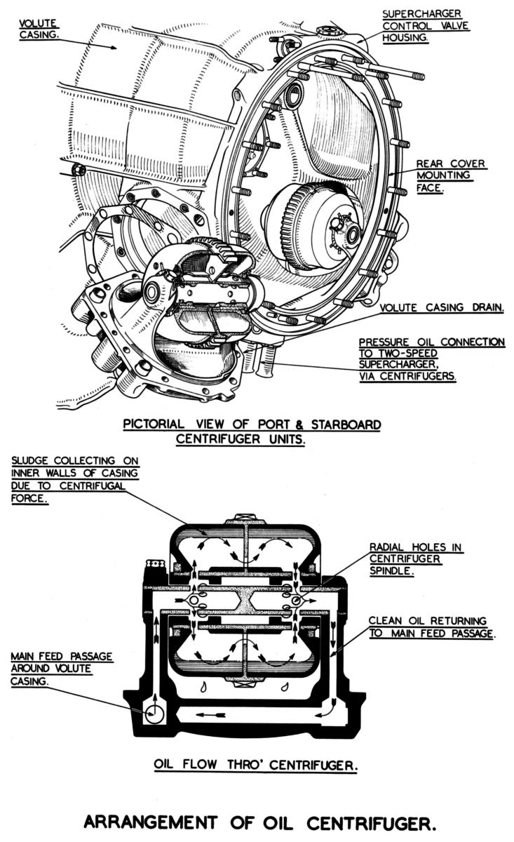
Engine oil is employed not only to change the gear ratio but also to hold the clutch plates in engagement, and consequently, it must be continuously fed to the clutch chamber of the engaged clutch. Since the clutches revolve at a high speed, any sludge in the oil is thrown out of suspension and deposited on the walls of the oil chamber. If this sludge were left to accumulate, the response to the change-over lever would be retarded or prevented, resulting in burnt or overheated plates. Two centrifugers are therefore fitted to prevent sludging and their construction is shown in Figure 16. These units are driven by the lowest of the three intermediate gears.
Oil flowing to the control valve enters the centrifugers through a duct in the brackets and then passes through the spindles to the first set of sludge traps. After leaving these traps, it is passed through two holes in the centrifuger gear faces to a second set of traps, and rejoins the main stream by flowing through the opposite end of the spindles and a second duct in the bracket. As it passes through the traps, centrifugal action removes a larger percentage of the sludge from the oil and deposits it on the walls and consequently only cleaned oil enters the clutches.
The centrifugers should be cleaned at the stated servicing periods and their dismantling is simple when using the special tools provided.
When a gear is in engagement, the centrifugers effectively clean the oil that enters the clutches but during a gear change oil surges through them too rapidly for them to remove any sludge held in suspension. An additional sludge trap is therefore fitted to each clutch housing and all oil entering oil chambers of the clutches must first pass through the traps. The provision of both centrifugers and sludge traps renders the sludging of a clutch unit extremely improbable.
 |
 |
 |
| Fig. 13 | Fig. 14 | Fig. 16 |
Send mail to
![]() with questions or comments about this web site.
with questions or comments about this web site.
![]()