UNITED STATES ARMY AIR FORCES
MATERIEL CENTER
MEMORANDUM REPORT ON
the
SZYDLOWSKI - PLANIOL SUPERCHARGER
May, 1942
Transcribed and Processed by J. Wells
Trentham, Victoria, Australia
January 2010
ARMY AIR FORCES
MATERIEL CENTER
MEMORANDUM REPORT ON
Date: May 23, 1942
SUBJECT: Test of the 12-Y-45 Hispano-Suiza Engine with a Szydlowski-Planiol Supercharger
SECTION: Experimental Engineering
SERIAL No.: EX-M-57-503-61
Expenditure Order No. 503-1-436
1. To submit the results of a test on the 12-Y-45 Hispano-Suiza engine with a Szydlowski-Planiol supercharger.
1. See Appendix 1 and Exhibits A to R, inclusive.
1. The Szydlowski-Planiol supercharger, as found by these tests, has a reasonably good efficiency however, not as high as that obtained by French tests.
2. There is a definite gain in efficiency, obtained by the use of tilting vanes at pressure ratios less than the maximum, which is very desirable for geared superchargers where the ratio of the tip speed to the engine speed cannot be varied. The range of load efficiencies for a given tip speed and tilting vane setting, is limited. Good efficiencies can be obtained for a load coefficient range of only about .02. However, by use of the tilting vanes, a fairly good range can be obtained by this supercharger without sacrificing much in efficiency.
3. The large changes in both the temperature rise ratio and pressure coefficients for small changes in load coefficients at tip speeds above 1000 feet per second, indicate that this supercharger is not adaptable for operation at a wide range of tip speeds.
Prepared by: WILLIS J. BROWN
Approved by: E. P. PAGE, Colonel, Air Corps, Chief, Power Plant Lab.
Approved by: F. O. CARROLL, Colonel, Air Corps, Chief, Expr. Engr. Sec.
(a) On December 13, 1941, the 12-Y-45 Hispano-Suiza engine, equipped with a Szydlowski- Planiol supercharger was received at the Power Plant Laboratory of the Materiel Center, Wright Field, Dayton, Ohio, for test.
(b) The primary reason for testing this engine was to determine the performance of the Szydlowski-Planiol supercharger since this supercharger is being built in experimental quantities in the United States for the Army Air Forces. This supercharger is unique in that, instead of using an ordinary throttle to reduce the pressure ratio for sea level operation, tilting vanes at the entrance to the supercharger are used to reduce the pressure ratio. The tilting vanes are constructed with the idea of utilizing some of the potential energy of the air flow, thus reducing the temperature rise through the supercharger.
(c) The construction of the supercharger is shown in the following listed exhibits:
Exhibit I - shows the impeller assembled.
Exhibit J - shows the diffuser vanes.
Exhibit K - shows the supercharger inlet.
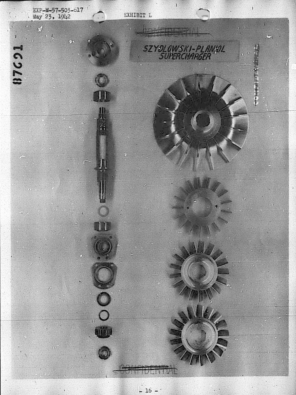
Exhibit L - shows the impeller disassembled.
Exhibit M - shows the supercharger outlet.
Exhibit N - shows the tilting vanes disassembled.
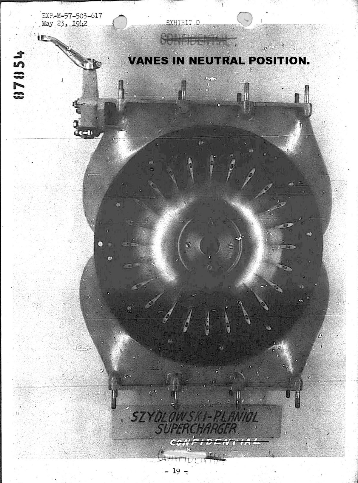
Exhibit O - shows the tilting vanes in the full open position.
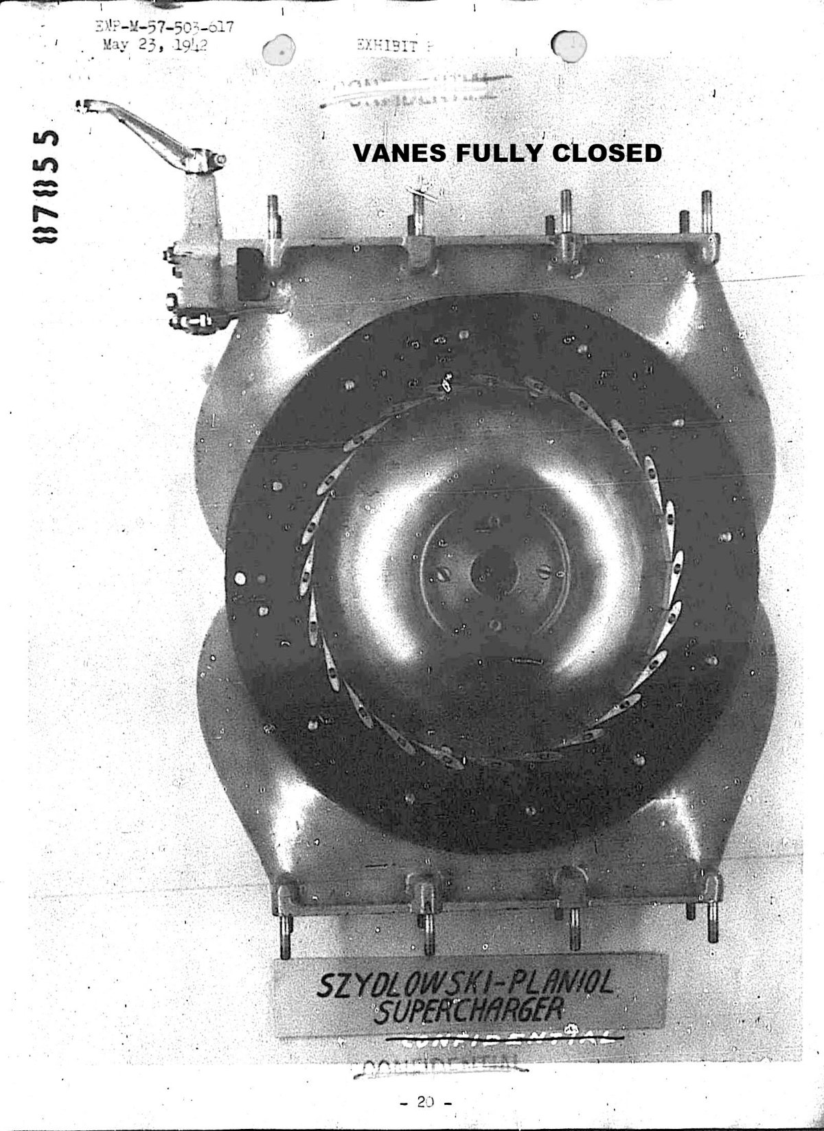
Exhibit P - shows the tilting vanes in the full closed position.
Exhibit Q - shows the operating mechanism for the tilting vanes.
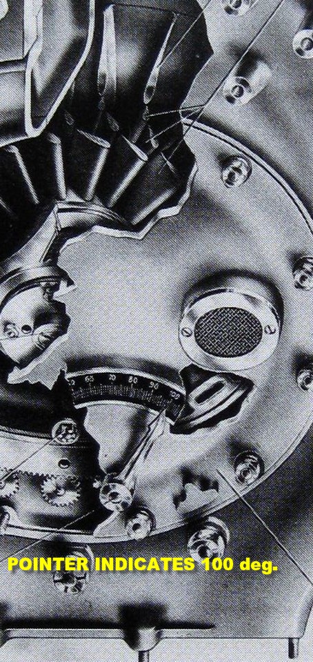
Exhibit R - shows a rear view of the supercharger assembly. The hand on the back travels along a scale graduated in degrees thus indicating the position of the tilting vanes.
(d) The engine, for which the supercharger was built, is a Hispano-Suiza Model 12-Y-45. It is a twelve cylinder, vee type, liquid cooled engine. The displacement is 2197 cubic inches and the maximum rating is at 2400 rpm and 34.6" Hg. manifold pressure. The ratio of supercharger impeller speed to crankshaft speed is 10.03 to 1 and the impeller diameter is 240 mm (9.45”) thus giving the impeller a tip speed of approximately 1000 feet per second at the maximum crankshaft speed.
(a) The engine was mounted with altitude equipment installed on dynamometer No. 11 of the Power Plant Laboratory. The altitude equipment is such that the exhaust back pressure can be reduced and the inlet air temperature and pressure can be controlled to simulate altitude conditions. Exhibits G and H show the installation.
(b) The engine was started on March 5, 1942. Considerable difficulty was experienced in getting the engine to run but a check was obtained at maximum altitude rating. The power was found to be low and the supercharger efficiency was much lower than that expected by Mr. Planiol, one of the men who developed the supercharger and who was present while the subject test was being run. As a result, the engine was removed from the stand and the supercharger disassembled for inspection.
(c) Disassembly inspection of the supercharger revealed that the impeller blades had been nicked by a foreign material. The impeller blades were stoned to remove the indentations. Mr. Planiol supervised the stoning of the blades but there was no way of checking the profile which may have been changed slightly by the stoning and thereby affecting the efficiency.
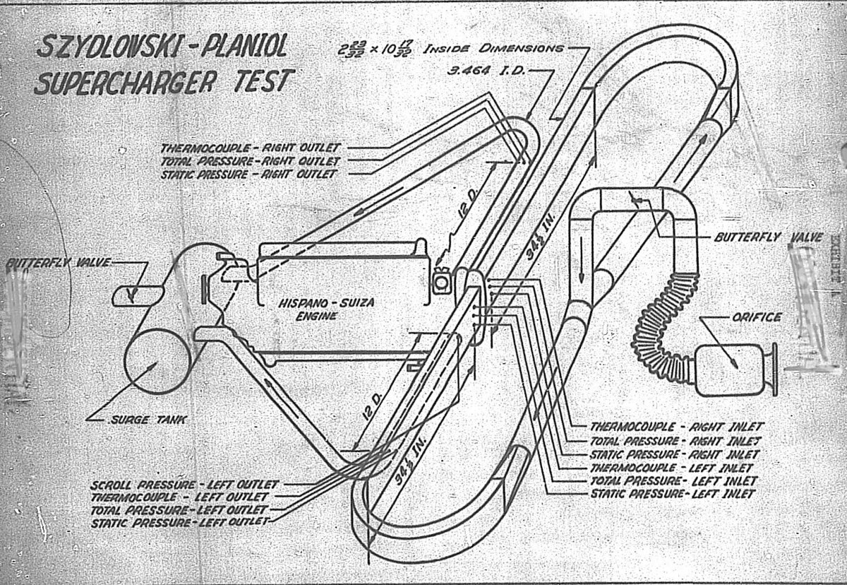
(d) Since representative altitude power checks could not be obtained because of the poor condition of the engine, it was decided to test the supercharger only. The test was conducted in accordance with "The Standard Procedure for Rating and Testing Centrifugal Superchargers" by the N.A.C.A. Special Subcommittee on Supercharger Compressors, dated February, 1942. The engine, with pistons and connecting rods removed, was used as a gear box for driving the supercharger. Temperature measurements were made with a Pratt & Whitney temperature probe with a known recovery factor. Exhibit A is a schematic sketch of the test set-up.
(e) Tests were run at impeller tip speeds of 500, 1000, 1100 and 1200 feet per second. Readings were taken with the tilting vanes set at 90, 95, 100 and 105 degrees for each tip speed and at 1000 feet per second, additional readings were taken at 85, 75, 60, 45 and 30 degrees to determine the effect of the tilting vanes on the supercharger performance. It was impossible to obtain a complete set of readings from pulsation to full throttle as the driving clutch for the supercharger was not capable of standing the load at full throttle. However, the range was wide enough to bracket the operating range of the supercharger.
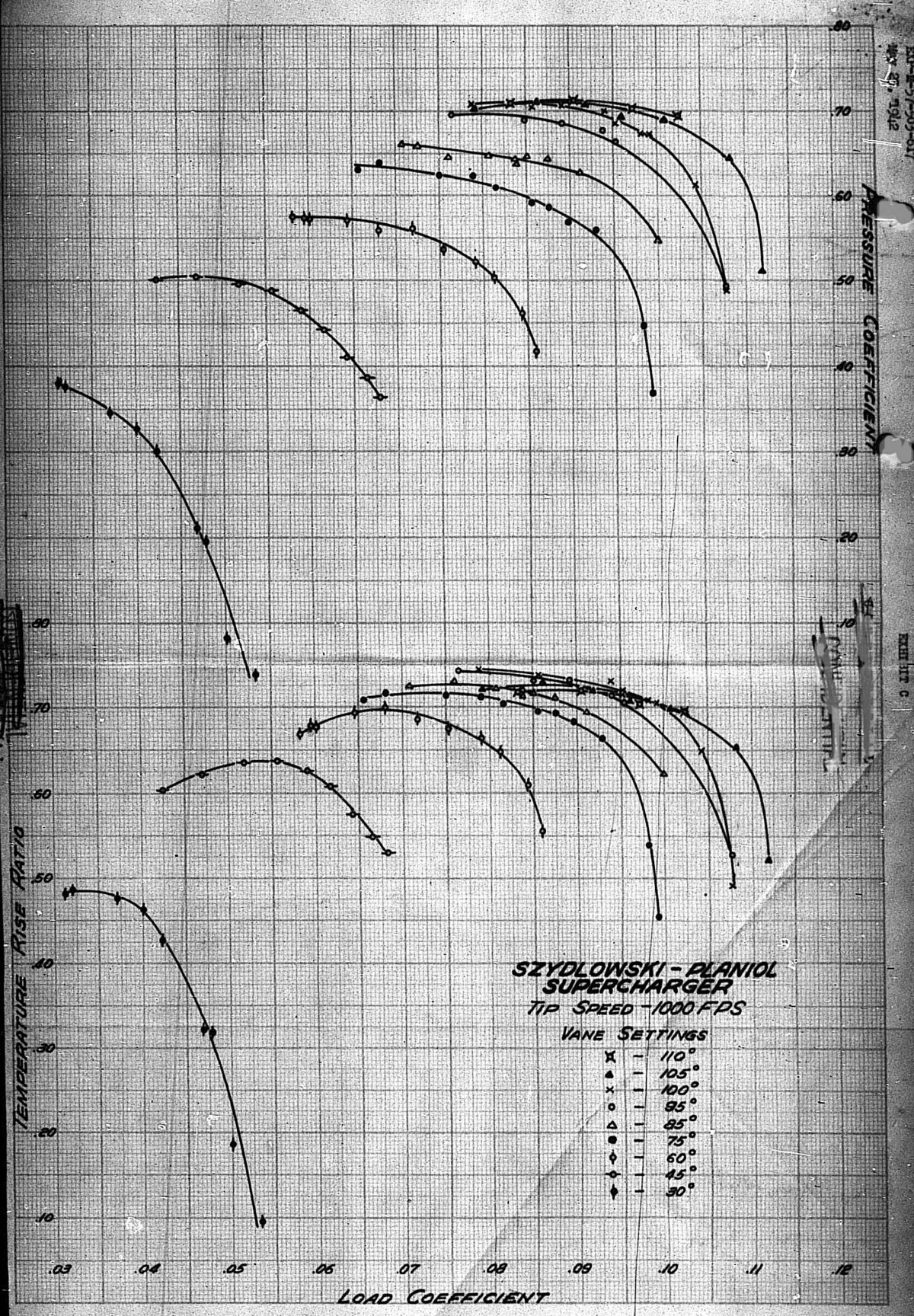
(a) The temperature rise ratio and the pressure coefficient for the various tip speeds are shown in Exhibits B, C and D. The pressure rise ratio at 60 degrees F is shown in Exhibit E. The maximum temperature rise ratio of 74.5 was obtained at 1000 feet per second tip speed with the tilting vanes set at 100 degrees. This is approximately 6-1/2 per cent below the maximum efficiency obtained from French tests.
(b) Part of the discrepancy of the results between the French tests and these tests can be explained by the difference in method of testing. The French use a value of 0.286 for the ratio y-1/y, whereas 0.283 was used for the computations in this test. The French measure a total pressure directly at the outlet of the supercharger, whereas in this test, the total outlet pressure was measured in a straight pipe, 12 diameters from the outlet. The French use mercury thermometers instead of standard temperature probes and make no corrections to obtain total temperatures. One other fact which may have also contributed to the discrepancy of results, namely, the fact that the supercharger tested was obviously in poor condition when received and part of its performance may have been destroyed by the stoning as previously mentioned.
(c) As pointed out in 1 (b), one of the interesting features of this supercharger is that the tilting vanes should give an increase in efficiency when operated at pressure ratios below the maximum. Exhibit F shows the gain in efficiency obtained by the use of the tilting vanes. The maximum efficiency possible to gain was found to be 15 per cent.
 |
 |
 |
 |
| Exhibit A - Test Set-Up Schematic | Exhibit C - Temperature-Rise Ratio and Pressure Coefficient | Exhibit L - Impeller Disassembled | Exhibit O - Tilting Vanes in the Full-Open Position |
 |
| Szdylowski-Planiol Supercharger Vane Angles |
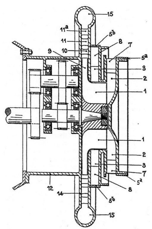
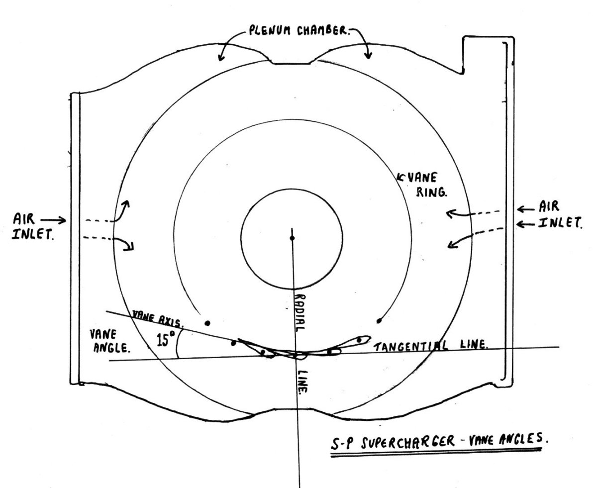
The feature that distinguished the Szdylowski-Planiol supercharger from all the others was the ring of swiveling vanes that determined the direction of the air after it entered the plenum chamber of the unit.
Throughout the Report, testing of the supercharger with the vanes inclined at different angles was undertaken. Values of 30° to 110° are sited frequently but nowhere is there an explanation of just where the base line for the angles between the long axis of each vane and this line actually is located!
The only line that seems to fit is the RADIAL TANGENTIAL for each vane, i.e., if a line is drawn from the centre of the supercharger to the centre of the swivel rod for any particular vane and then another line is drawn at right angles to this also passing through the centre of the swivel-rod, then this is the 0° base (see Fig. 1).
If this is the case, then the vanes, when fully closed (i.e., lying head-to-tail in a circle) would rest at an angle of approximately 15° to the radial tangential lines. When the vanes are opened so that each one points straight at the centre of the supercharger, then the angle between the vane axes and the radial tangential lines will be 90°.
This should have been explained by Willis J Brown and his team.
When the vanes are at 15° they completely block the flow of air into the supercharger. If the vanes are opened slightly to say, 20°, air can enter but only in limited quantities. Thus, in situations where the engine is working hard in a dense atmosphere e.g., at take-off or in a climb, the limited openings of the vanes can prevent over-boosting. This function is recognized in the Report as, "This supercharger is unique in that, instead of using an ordinary throttle to reduce the pressure ratio for sea level operation, tilting vanes at the entrance to the supercharger are used to reduce the pressure ratio."
As long as the vanes are angled to the airflow between about 20° and about 85°, they will impart a degree of swirl to the air moving from the plenum chamber through to the inducer (rotating inlet guide vanes). Effectively, the vanes act as a zero-stage for the (three-part) inducer. This reduces the shock of the air meeting the fast rotating inducer and thus allows the supercharger to operate at a slightly lower temperature than would otherwise be the case and therefore, work with greater efficiency.
 |
| Szdylowski-Planiol Supercharger Vane Angle Effects |
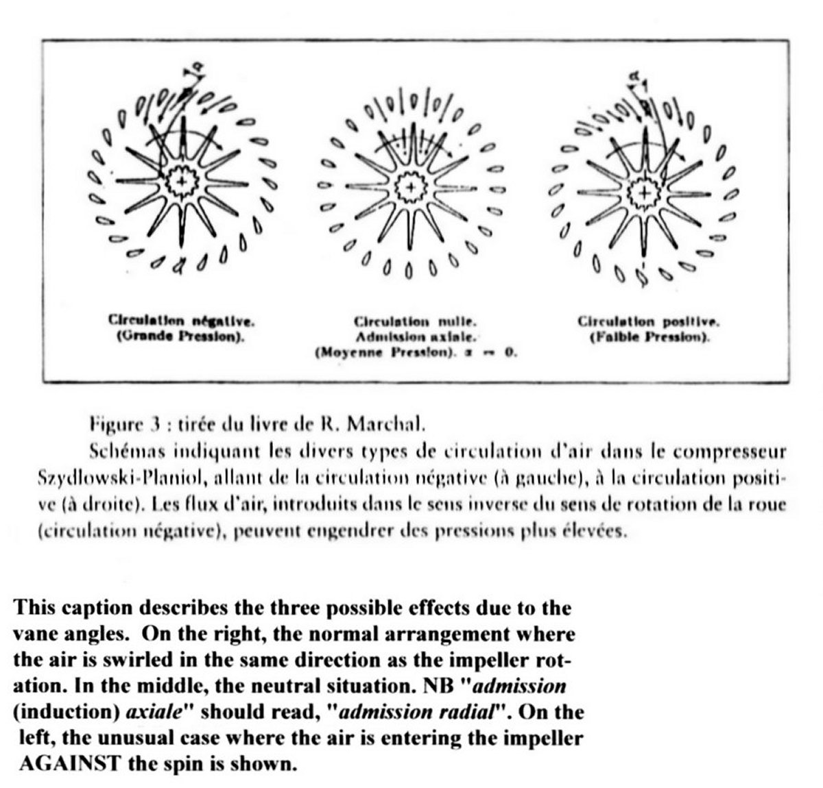
If conventional wisdom applied, the vanes in this supercharger would be prevented from ever reaching an angle of 90° or more. This is because at 90°, any swirl effect on the air ceases thus allowing the air to hit the inducer axially with resultant shock, turbulence and temperature rise.
However, as can be seen in the performance graphs, not only can the vanes be set at 90° but they can go round another 20° past this point to 110°! From this position the vanes are swirling air at the inducer in the opposite direction to the inducer's rotation. This positive and negative circulation is recognized in the French literature, (see Fig. 2) but strangely, this extraordinary situation invokes no comment at all from Brown and his associates including M. Planiol, the designer!
In my opinion, this Report is deficient in that it fails to establish several important base performance parameters, namely:
a/ the zero-degree line for the vane angles,
b/ the performance of the supercharger with the vanes removed and,
c/ the performance with the vanes in the 90° position ie, where they don't bend the airflow one way or the other.
Without careful measurement of b/ and c/, the true effect of the vanes cannot be shown.
 |
 |
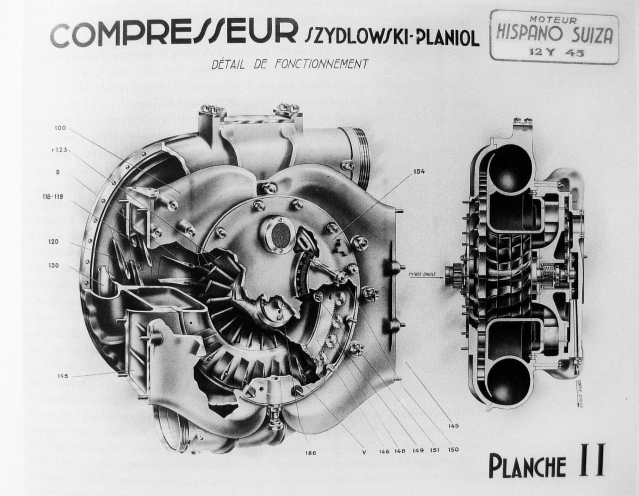 |
| Szdylowski-Planiol Supercharger with Vanes Closed | Close-up of Szdylowski-Planiol Supercharger Vane Angle Indicator | Sectioned View of Szdylowski-Planiol Supercharger |
Send mail to
![]() with questions or comments about this web site.
with questions or comments about this web site.
![]()