

More on this aircraft.
Nelson H-59 Engine Restoration
Article and Images by Vic Bentley
Published 4 Dec 2019
Introduction
The Canadian Museum of Flight in Langley, BC Canada has a number of old engines in storage. One that interested me was a horizontally-opposed, four-cylinder, two-stroke cycle, single-ignition air-cooled engine. This was, supposedly, off the Bowlus/Nelson Dragonfly that the Museum has on display.(Pic 1) This powered glider from 1947 was put into limited production and the Museum’s example was flown locally.
The engine listed for this aircraft was the H-44 of 25 hp and it was presumed that this was the engine the Museum had in storage. It wasn’t until later, from measuring the bore and stroke, that the engine was identified as the 40 hp Nelson H-59. Perhaps this engine was purchased to fit in the Dragonfly to improve its performance under power. The engine shows evidence of having run, however the glider was fitted with a fairing over the engine compartment when donated to the Museum.
As the engine was a rare Museum artifact, the task was considered to be a restoration to display standards and no attempt would be made to run the engine. The first step was to make a detailed photo record, having learned that memory is not sufficient to recall all the details when it comes to reassembly weeks or months later.
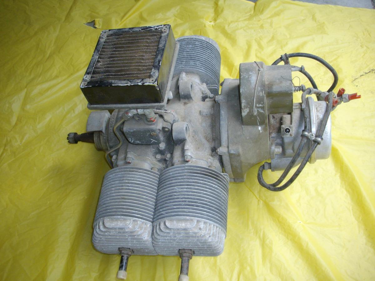
The engine had light surface corrosion and dust and debris from being in storage. There were no obvious broken or missing parts, although the starter pull-cord mechanism was missing.(Pic 2, Pic 3)
|
|
|
| Pic 1. The Bowlus/Nelson Dragonfly on display at the Canadian Museum of Flight. More on this aircraft. |
Pic 2. The Nelson engine before restoration exhibits light debris from being in storage. | Pic 3. The engine before restoration. The name NELSON in the casting makes identification easy. |
Ignition system
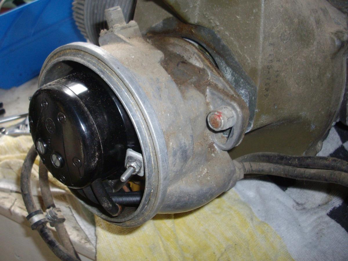
At the rear of the engine (opposite to the prop shaft), a cast aluminum housing contained the magneto and distributor with wires leading to the four spark plugs. A clamp held an aluminum cover in place. The housing was attached to the crankcase by lugs with slots allowing the timing to be adjusted. (Pic 4) It is interesting to compare this arrangement with the Righter O-15 engine and see an identical setup, suggesting a common supplier.
The magneto was driven by a machined coupling with two dogs that engaged via a rubber coupling to the engine. The coupling is an impulse type. (Pic 5)
Fuel system
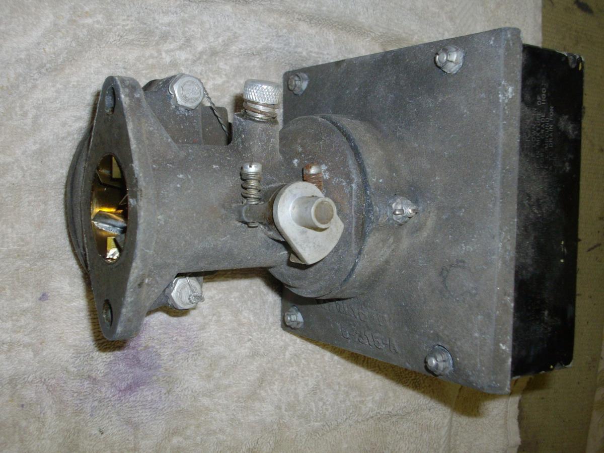
The carburetor and air filter housing were both cast units, apparently of Nelson design. The carburetor was attached to the engine near the center of the crankcase. Near the exit of the carburetor were six vanes inclined to the airflow that would impart a swirl to assist mixing of the fuel and air. (Pic 6, Pic 7) Fuel to the engine passed through a fuel filter.
 |
 |
 |
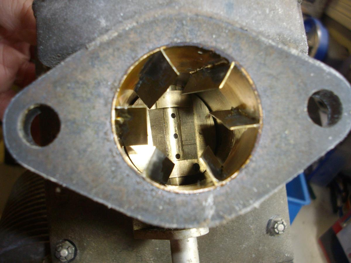 |
| Pic 4. The cast aluminum housing contained the magneto and distributor with wires leading to the four spark plugs. | Pic 5. The magneto was driven by a coupling with two dogs that engaged a rubber coupling. | Pic 6. The carburetor and air filter were attached to the engine near the crankcase center. | Pic 7. Near the carburetor exit were six vanes that assisted mixing fuel and air. |
Starting system
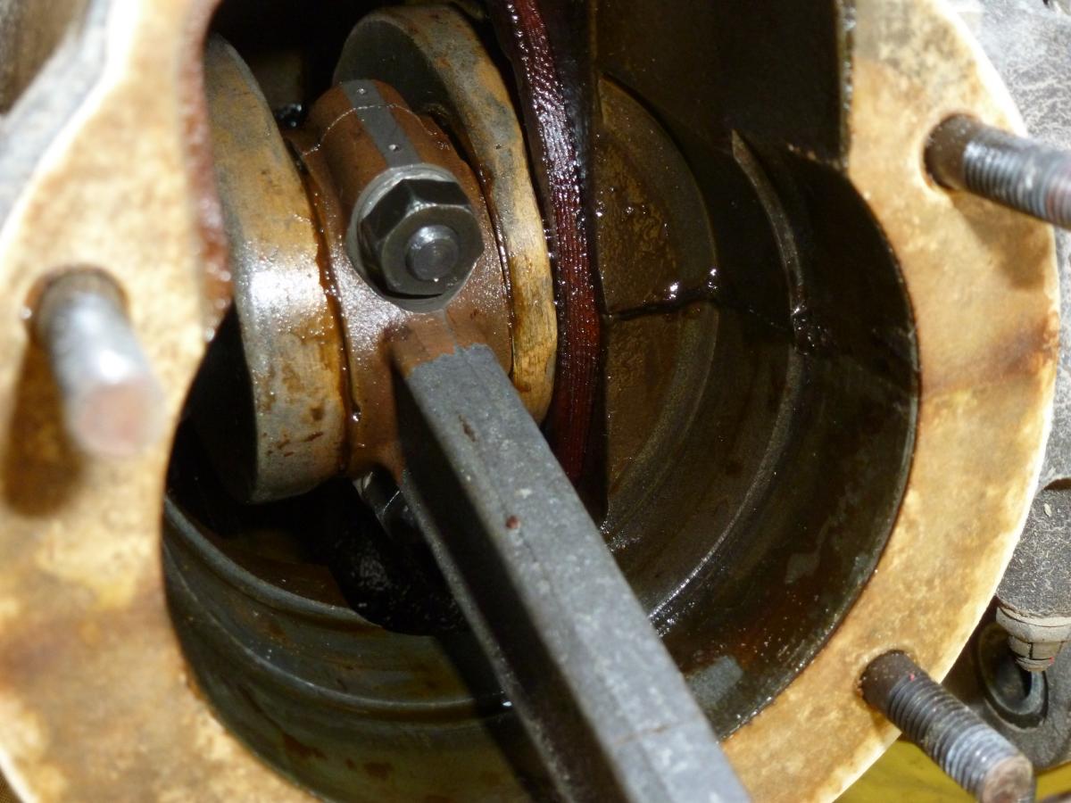
Between the distributor and the crankcase was an ingenious starting system. The recoil starter could be used on the ground and also inflight. A toothed belt was driven by the recoil starting mechanism to the crankshaft. (Pic 8) Pulling the starter cord would turn the engine via the toothed belt. Unfortunately, no starter cord and recoil mechanism were with the engine. The mechanism, having the same characteristics as a modern lawnmower, would disengage once the engine started.
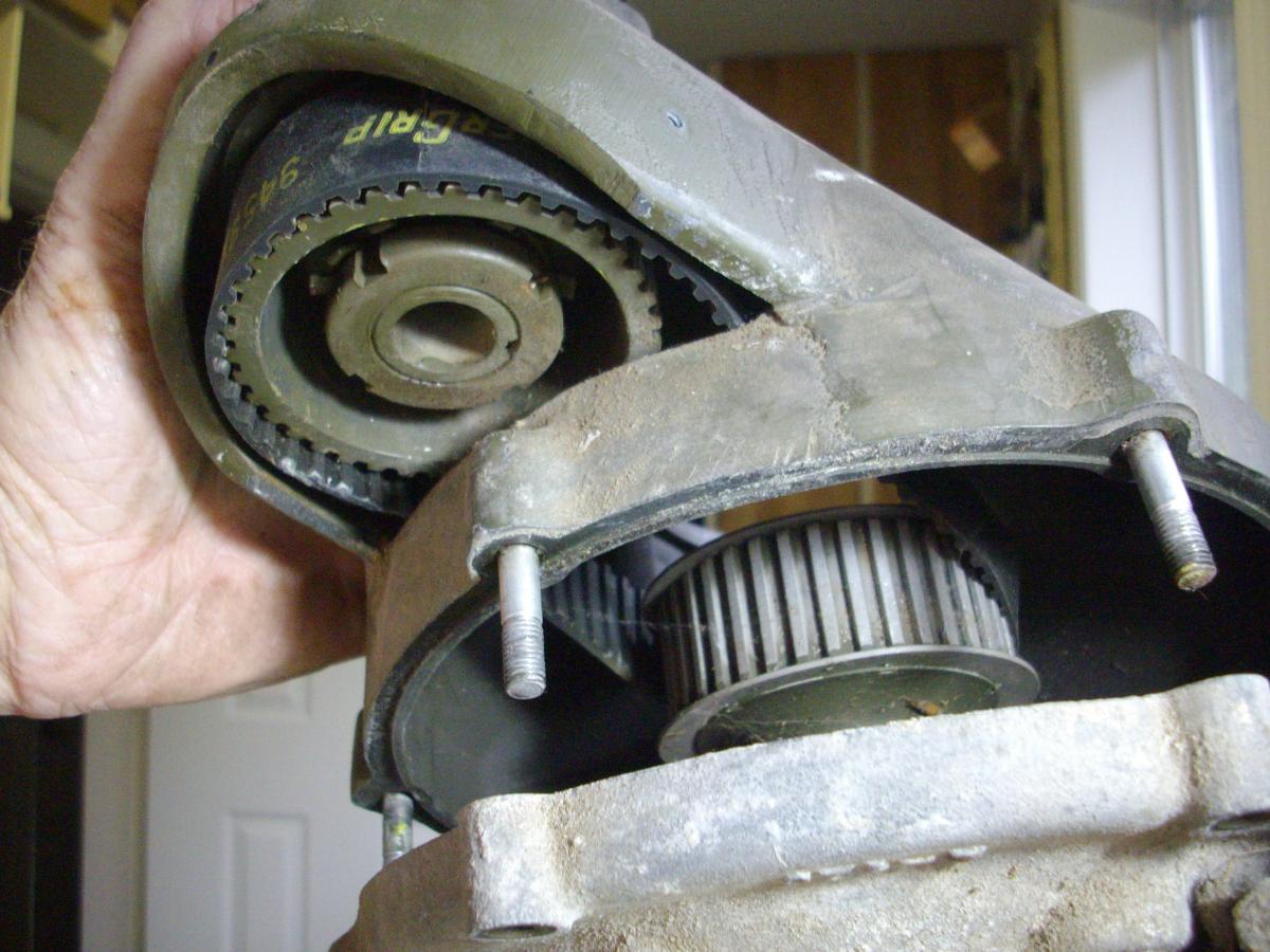 |
| Pic 8. The recoil starting mechanism drove a toothed belt to the crankshaft. |
Construction
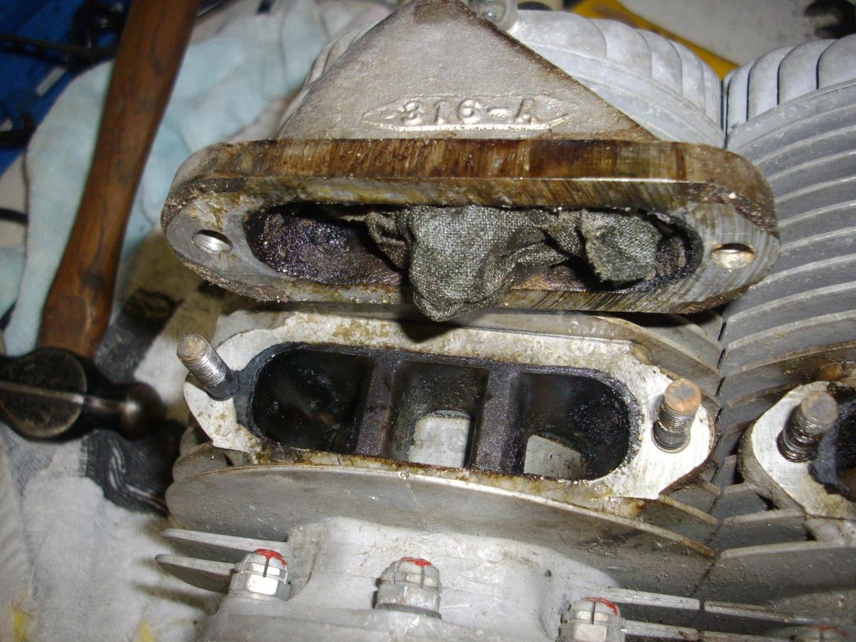
The four exhaust ports had short stub exhaust pipes each with an oily fabric tucked inside. When these were removed the pistons were visible in the cylinder heads. The exhaust ports and pistons were well lubricated. The residue on the ports showed the engine had been in running condition. (Pic 9) Each cylinder head had its appropriate number stamped in the metal.
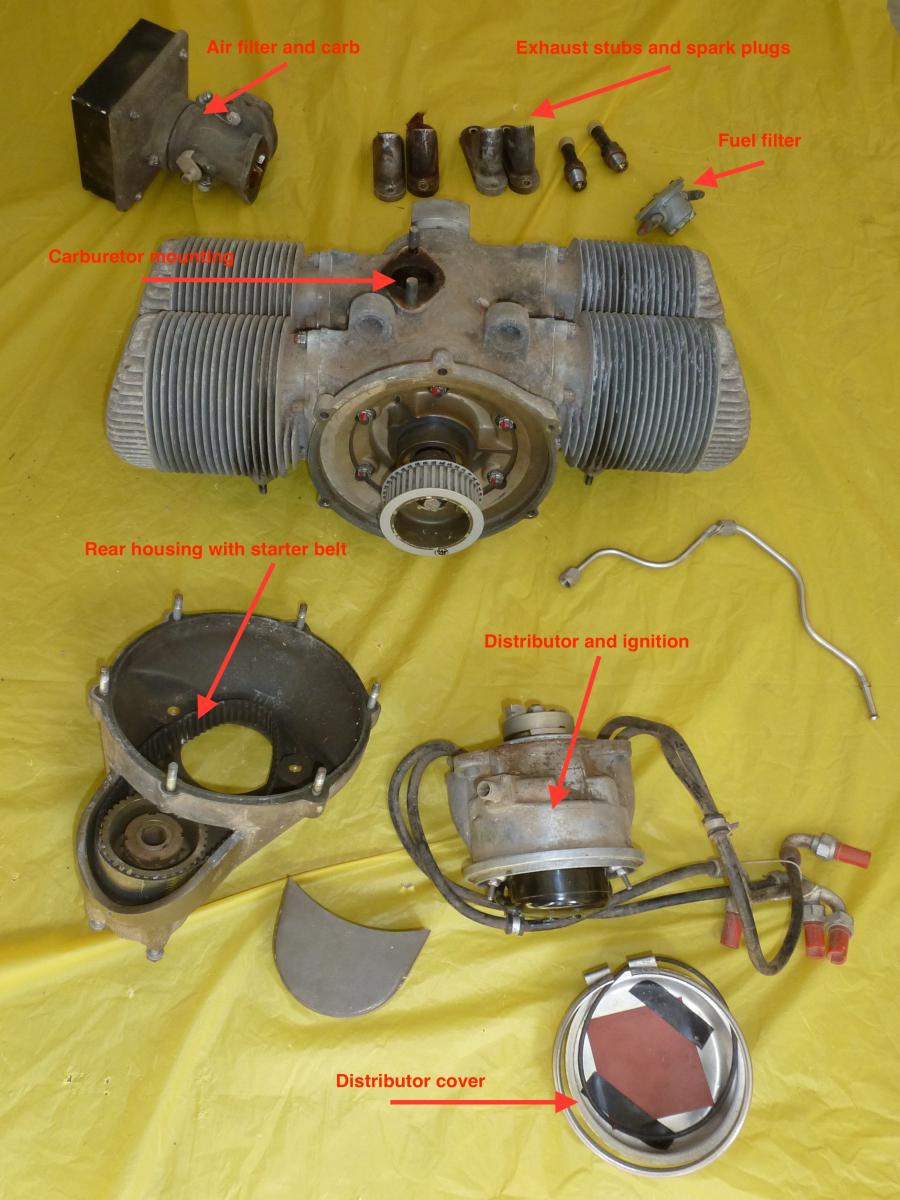
The major components are shown as dismantled. (Pic 10)
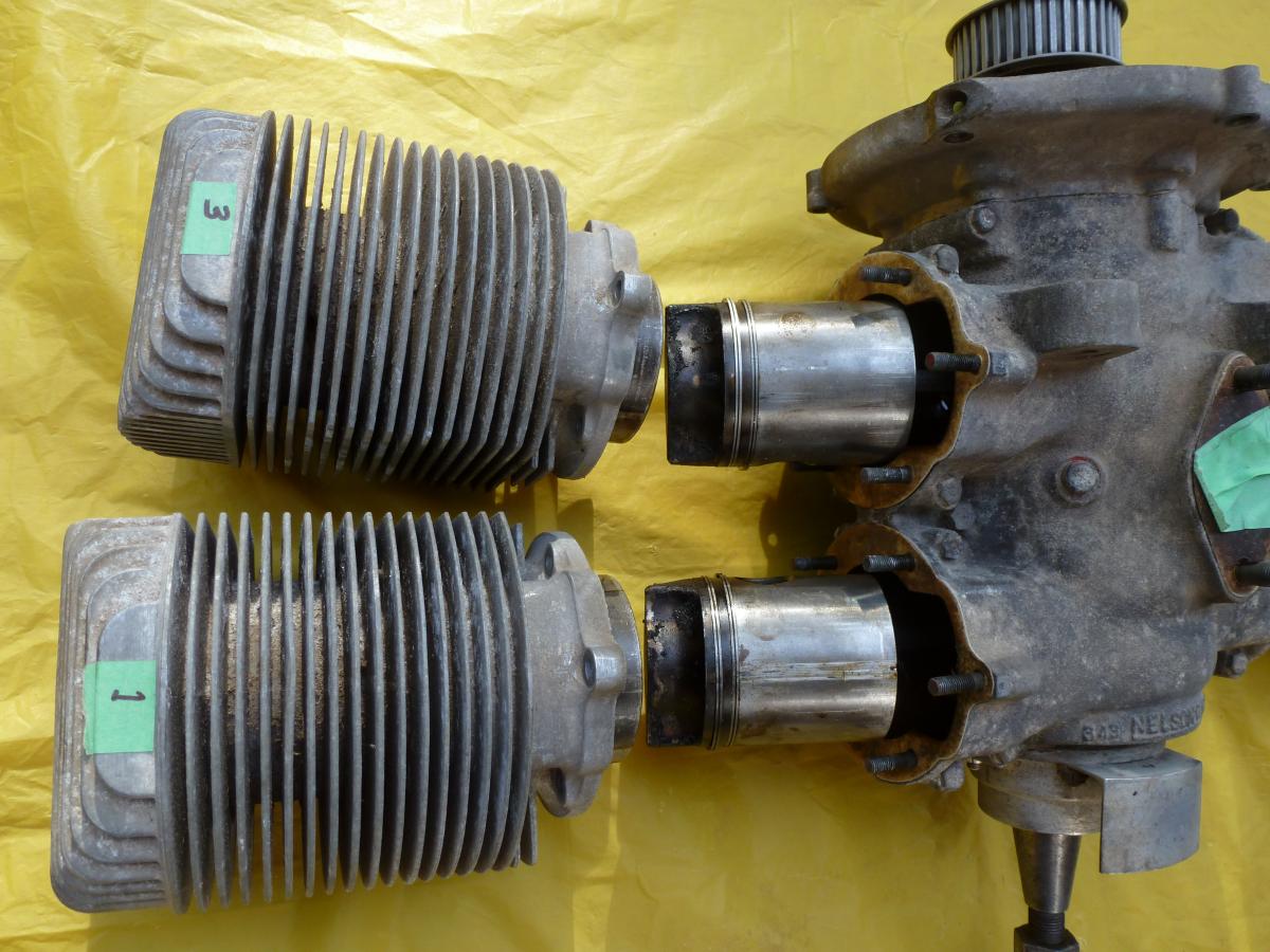
The six hold-down nuts were removed from each cylinder and the heads removed. (Pic 11) All parts were in a well lubricated state and removed readily. The carbon buildup on the pistons and exhausts indicated that the engine had been run for a number of hours. Inspection of the interior of the engine by looking past the connecting rods showed it was lubricated and in good condition. (Pic 12) The inside of the cylinders showed light carbon buildup and no scoring of the cylinder walls.
 |
 |
 |
 |
| Pic 9. The residue on the ports showed the engine had been in running condition. | Pic 10. The major components are shown as dismantled. | Pic 11. Six hold-down nuts secured each cylinder. | Pic 12. The engine interior, looking past the connecting rods, was in good condition. |
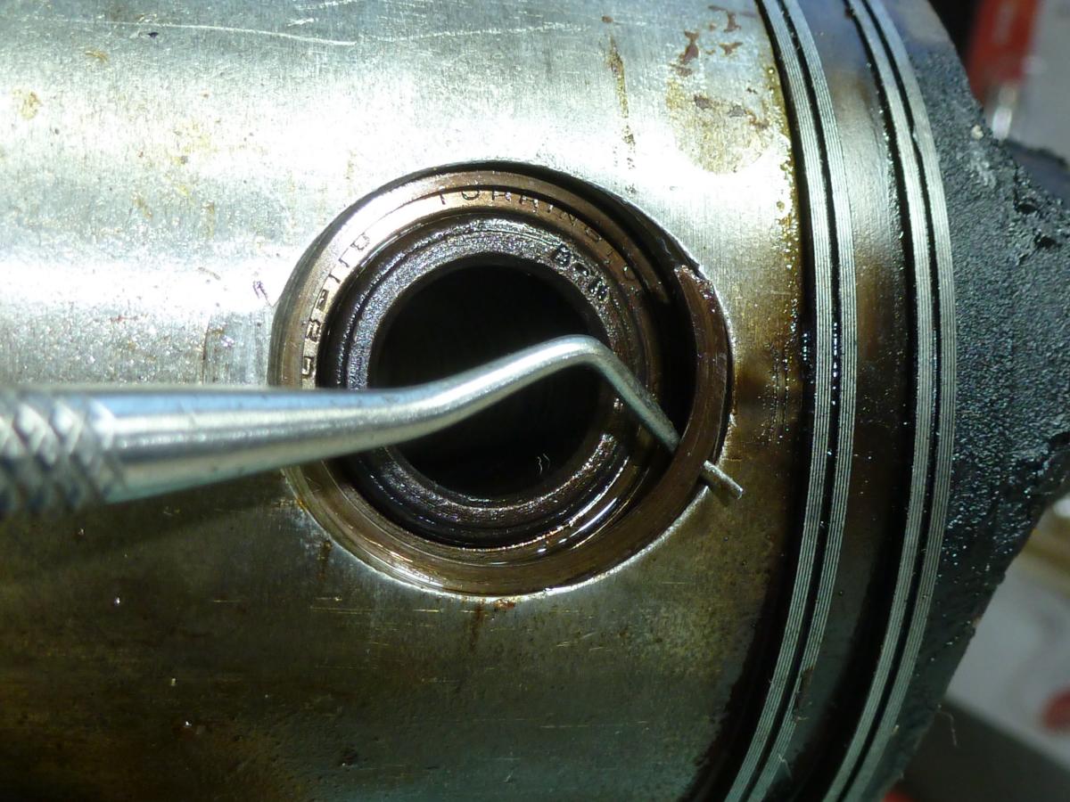
The piston pins were held in position by a circlip. Removal of the circlip showed that there were ball bearings supporting the piston pin. The name of the bearing manufacturer was visible – Torrington. (Pic 13) Wikipedia notes that this later became the familiar Timken Bearing Co.
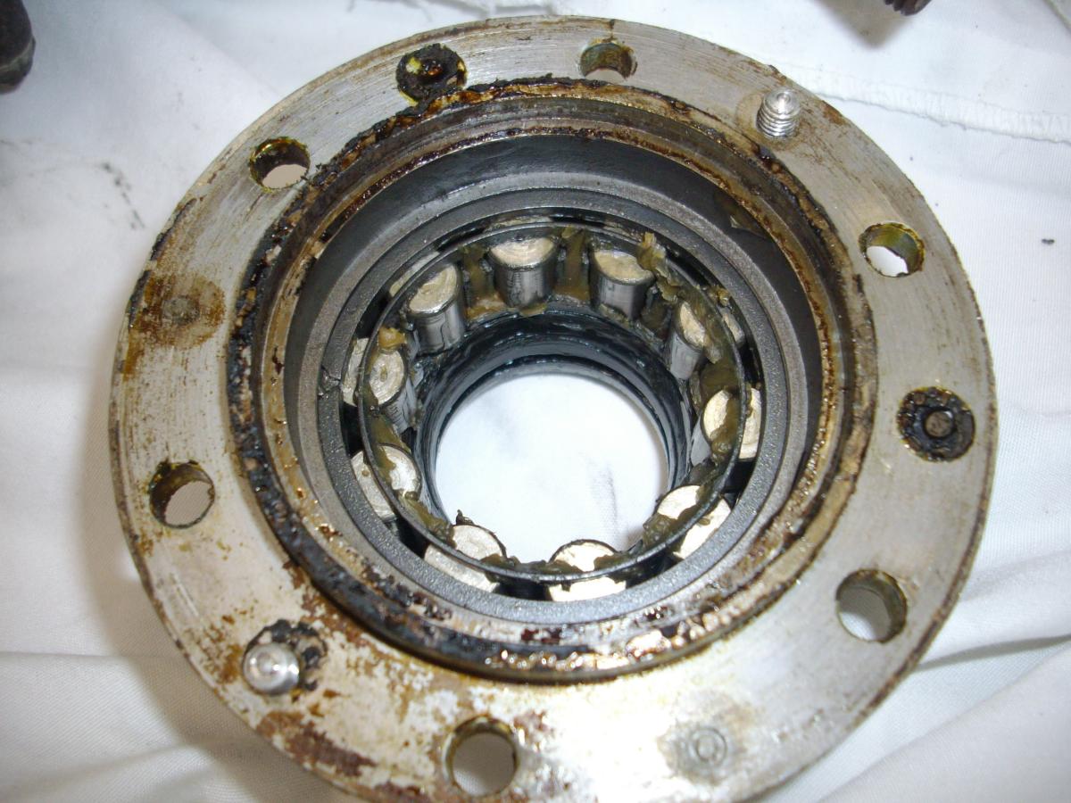
The front bearing at the prop shaft was removed along with the ignition timing marker. The bearing housing was a substantial machined fitting and enclosed roller bearings. (Pic 14) This revealed a ball bearing held in place by a circlip inside the crankcase. No further dismantling of the engine components was done.
The cylinder heads and crankcase were glass-bead blasted making them look as good as new – maybe 60 years after manufacture. (Pic 15) Priming and painting completed the effort. (Pic 16, Pic 17)
 |
 |
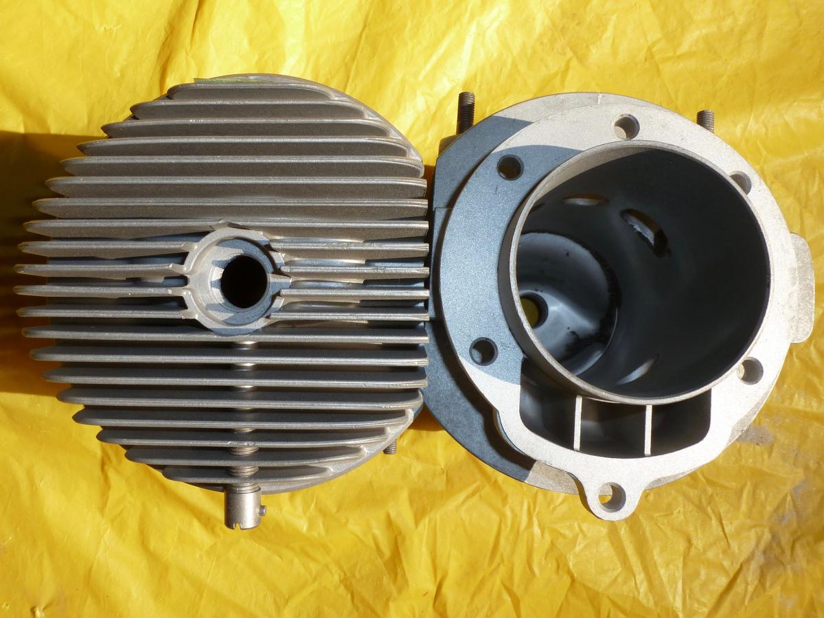 |
| Pic 13. The piston pins were held in position by circlips. | Pic 14. The front prop shaft bearing was a substantial machined fitting that enclosed roller bearings. | Pic 15. The cylinder heads and crankcase were glass-bead blasted. |
 |
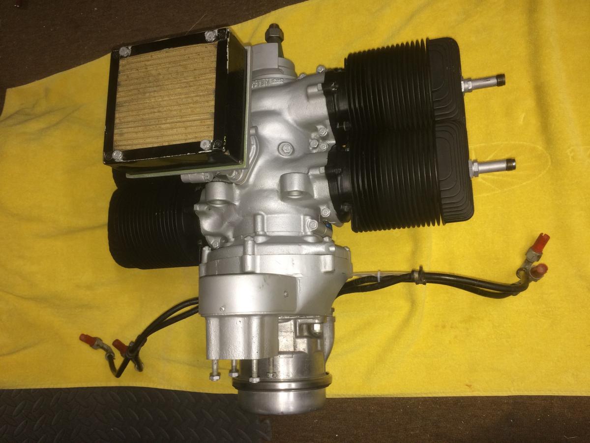 |
| Pic 16, 17. Priming and painting completed the effort. | |
I have been unable to find any documentation for the engine. Considering that it powered the Hiller XROE-1 Rotorcycle that was tested by the US Marine Corp. there must be some documentation out there. The Nelson H-59 for this mini-copter was built by Barmotive Products Inc. of San Leandro, CA.
This writeup for the Hiller XROE-1 gives detail of the H-59 operation;
The H-59 was a horizontally opposed, four cylinder, two cycle, air cooled engine with a rated power of 40 hp at 4,000 rpm. The engine was designed to run on 80/87aircraft fuel mixed with S.A.E. 30 oil with a ratio of one part oil to eight parts gasoline. The engine could be operated with standard automobile gas but with a slight reduction of power. The XROE-1 engine was started with a lawnmower-type pull cord. The later YROE-1’s utilized a battery powered starter. The bare engine weighed only 42 pounds — but the addition of exhaust stacks, carburetor, ignition coils, electrical generator, starter motor, and a 12-volt battery brought the total engine weight to 57 pounds.
The H-59 air cooling system consisted of a 13-inch axial flow fan providing low-pressure, high-flow air through the engine shrouding and which also served as the engine's flywheel.
Engine vibration isolation was accomplished by the use of four rubber mounts between the engine crankcase housing attach points and the airframe.
A 2.5-gallon-capacity fuel tank was mounted above and behind the engine and functioned as a gravity feed system.
Send mail to
![]() with questions or comments about this web site.
with questions or comments about this web site.
![]()