
Restoration to Running of a
1944 Righter O-15-3 Gunnery Target Drone Engine
by Tom Fey
Published 1 Jul 2019; Revised 11 Jul 2019
I’ve shared my two previous drone engine restoration projects with the AEHS membership; however my restoration of the 1944 Righter O-15-3 engine was the first complete tear down of this type of engine for running and thus may have more to add to the WWII drone engine story. And remember, the way I did things isn’t necessarily the way they should be done.
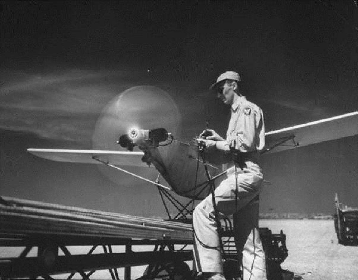
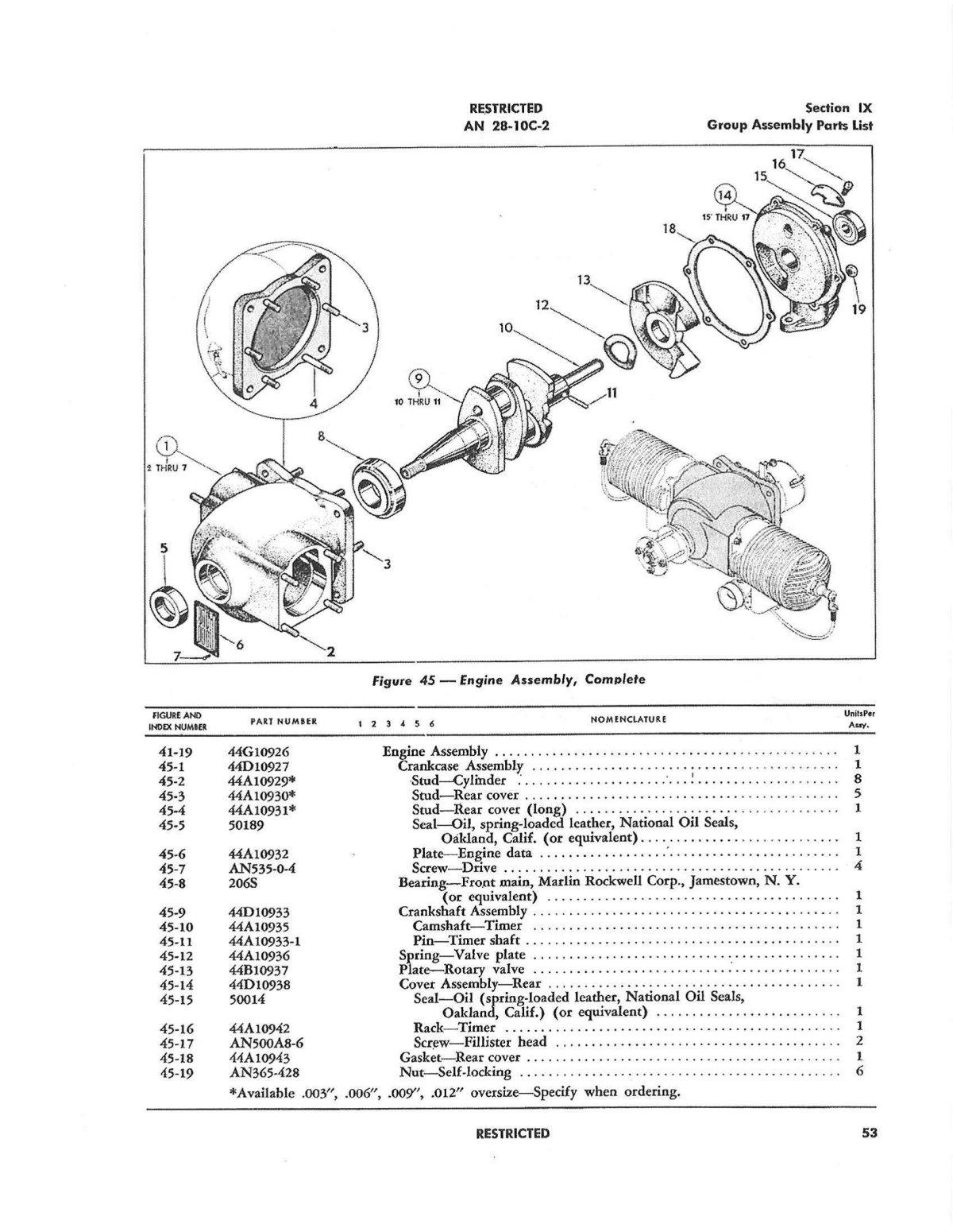
Like the other WWII production drone engines, the O-15-3 is a two cylinder, two stroke/cycle, horizontally opposed, simultaneous firing, unthrottled engine that used a battery-points-dual coil ignition system. The O-15-3 was designed by Walter Righter and manufactured by both Righter Manufacturing Company of Burbank, California and McCulloch Aviation of Milwaukee, Wisconsin. The engine displaces 16.7 in³ (277 cc), has a bore of 2.25", a stroke of 2.125", and generated eight hp at 3,800 rpm when it was new. The O-15-3 powered the 146" span, 97 pound, catapult launched, radio controlled Radioplane OQ-3/TDD-2 gunnery target drone to 102 mph. (Pic 1, Pic 2, Pic 3).
|
|
|
| Pic 1: Radioplane OQ-3 (Army designation) with Walter Righter-designed O-15-3 engine on the catapult. Note radio control box on a monopod and headphones resting on his forearm. Each command (up elevator-down elevator-left rudder-right rudder) had a different tone to aid control of the drone. | Pic 2: Exploded diagram of the O-15-3 cylinder and ignition timer (spark advance) assemblies. | Pic 3: Exploded diagram of the O-15-3 crankcase and contents. |
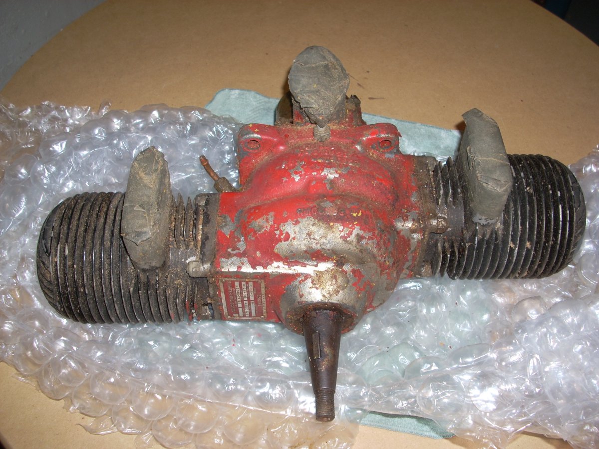
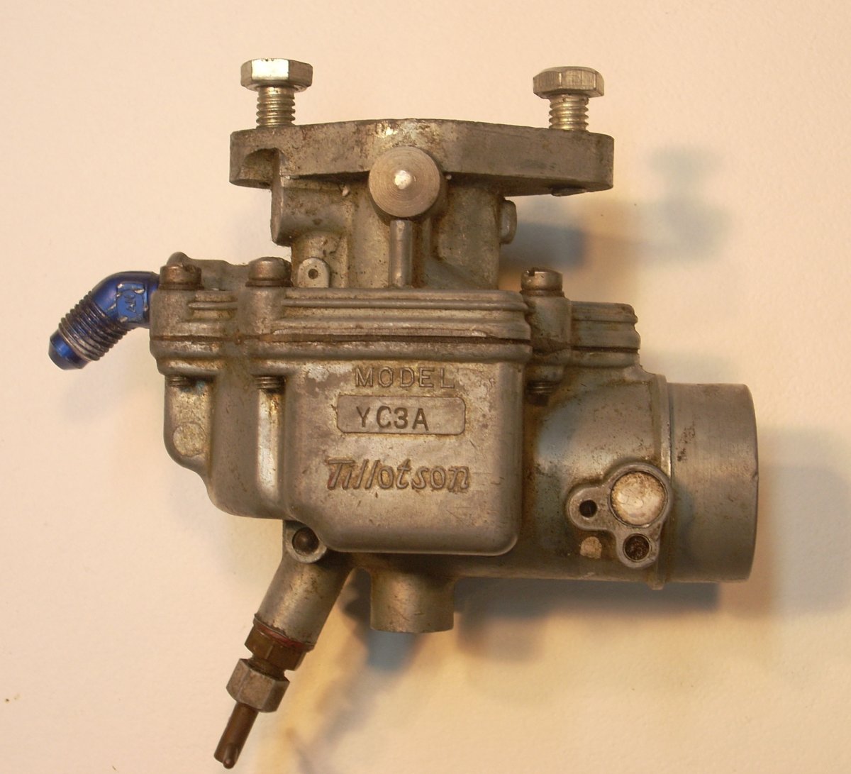
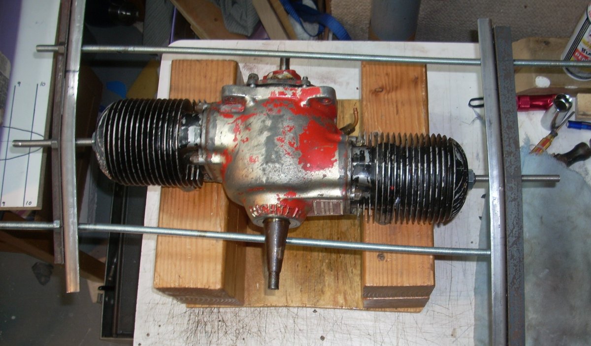
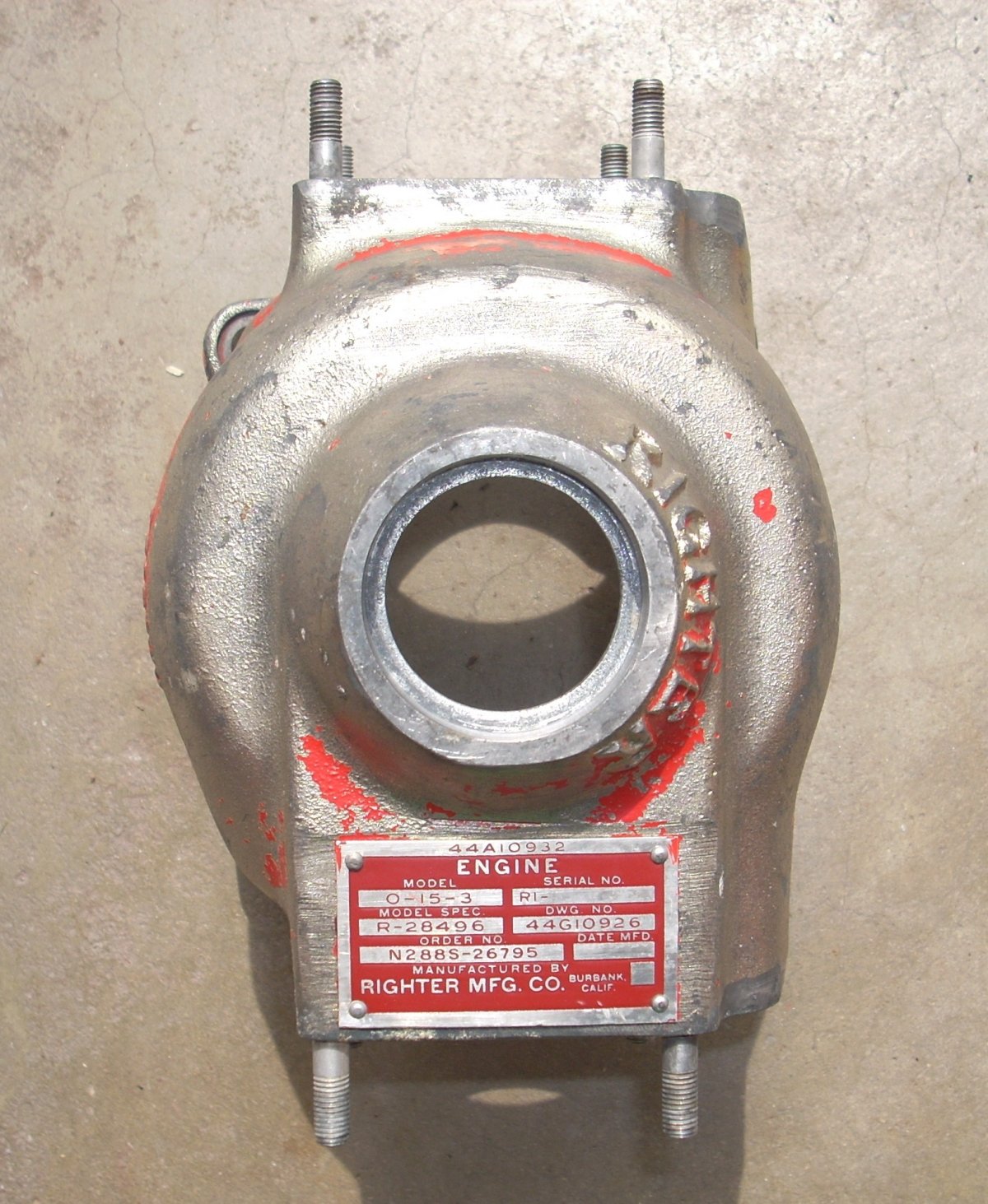
I purchased my O-15-3 off Craig’s list - St. Louis, Missouri, for $250 in 2015. It lacked the propeller hub and flange, but the ignition timing assembly (timer) and stock Tillotson YC3A carburetor were included and in good condition. (Pic 4, Pic 5, Pic 5a)
 |
 |
 |
| Pic 4: Righter O-15-3 engine on arrival. | Pic 5: Original Tillotson YC3A updaft carburetor for the 0-15-3 engine. | Pic 5a: Schematic of the Tillotson YC3A carburetor. No throttle of idle circuit is present in the design. |
The pistons were near top dead center in the bore, and unlike my other project engines, stubbornly resistant to crankshaft rotation even after a couple weeks of Chicago summertime heat and one can of PB Blaster penetrating oil distributed regularly into every orifice. I presumed corrosion of the cast iron piston rings and or the cast iron cylinder liner to be the problem.
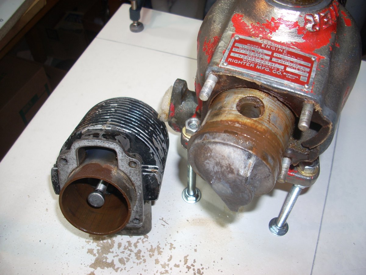
I bought some 18 mm spark plug inserts to protect the plug thread while flattened carriage bolts were inserted to seat on top of the piston crowns. An angle iron frame compressed via threaded rods functioned as a piston press. (Pic 6) The pistons still would not budge. So anti-seize lubricant on the threaded rods and a doubling of the angle iron frame got them to move a little, then a little more, and finally to bottom dead center. Removing the cylinders and rear cover of the engine revealed a rusting mess. (Pic 7, Pic 8)
 |
 |
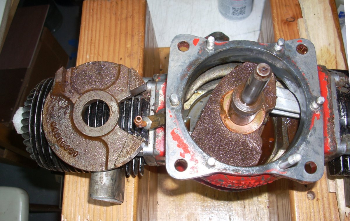 |
| Pic 6: Piston press consisting of a ram through the spark plug hole to the piston crown and an angle iron frame work compressed by advancing nuts on threaded rod. Note the bow in the angle iron and silvery plating in the crankcase which is worn away on the very top of the crankcase and the base of the cylinders in this view. | Pic 7: First cylinder off showing the flat headed ram in the bore of the cylinder and the corroded cylinder sleeve and piston rings swimming in penetrating oil. | Pic 8: Rear engine case has been removed (not shown) revealing the corroded crankshaft and light rust on the back side of the cast iron rotary valve which is lying on the cylinder. The brass compression washer on the tail of crankshaft applies pressure to the rotary valve to keep it seated against the face of the rear cover. |
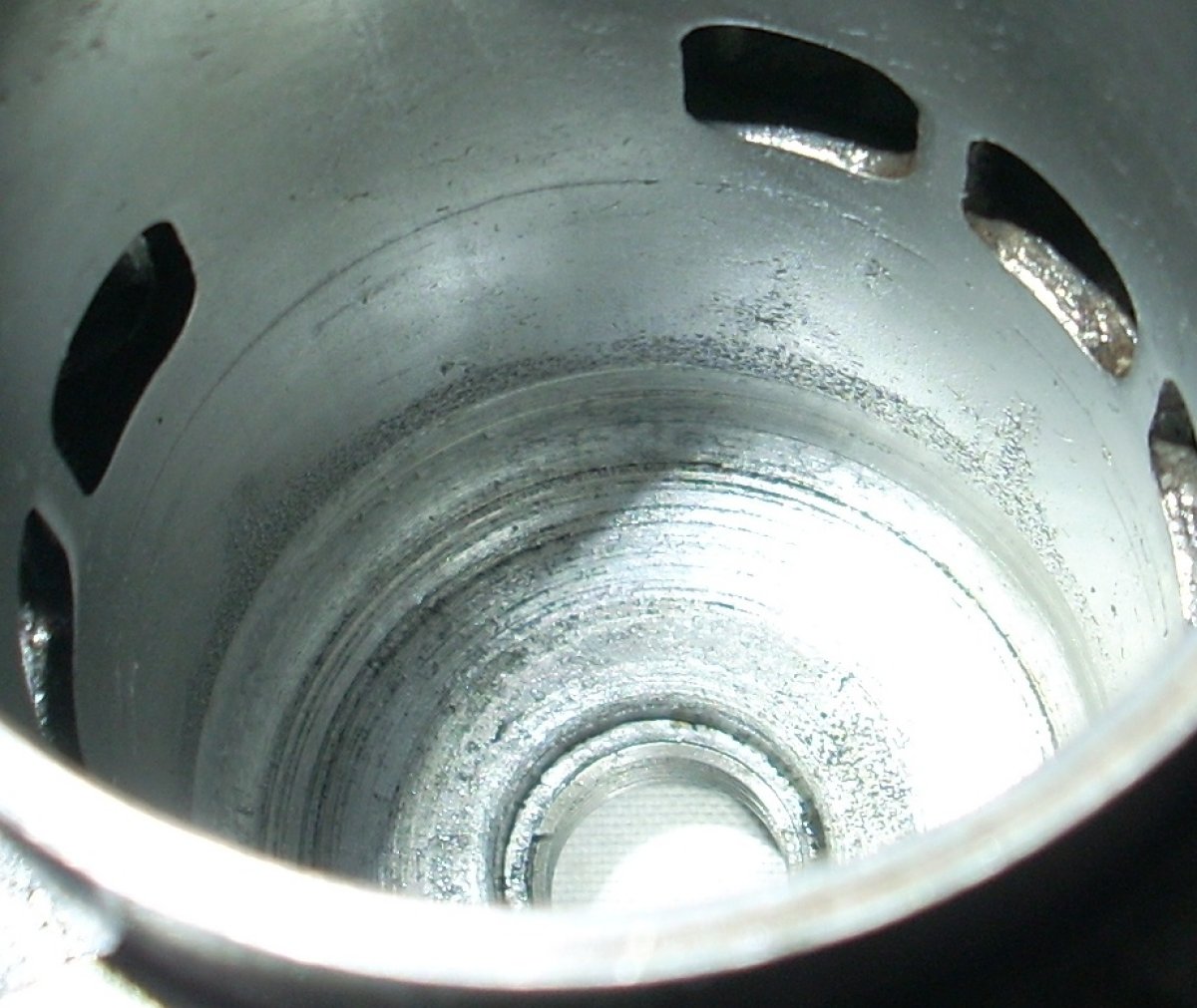
The cylinder liners were corroded and deeply pitted where the piston rings moldered in the bore; likewise the piston rings and wrist pins. (Pic 9, Pic 10, Pic 11). The piston crowns and combustion chamber had modest amounts of carbon, indicating it had been run. Running a ball hone through the bore did not erase the pockmarks in the cylinder walls, and replacement liners, oversize pistons and rings were not available. Disappointingly, the crankshaft was essentially frozen in its new position, leading me to believe the thrust ball bearing in the nose was the issue, and indeed it was. The bearing was locked forever by corrosion, and the piston press either turned the crankshaft in the frozen inner race of the bearing, or the whole frozen bearing inside the crankcase. So off came the aluminum pistons and connecting rods, which, despite the penetrating oil/rust sludge, were found to be in good condition.
 |
 |
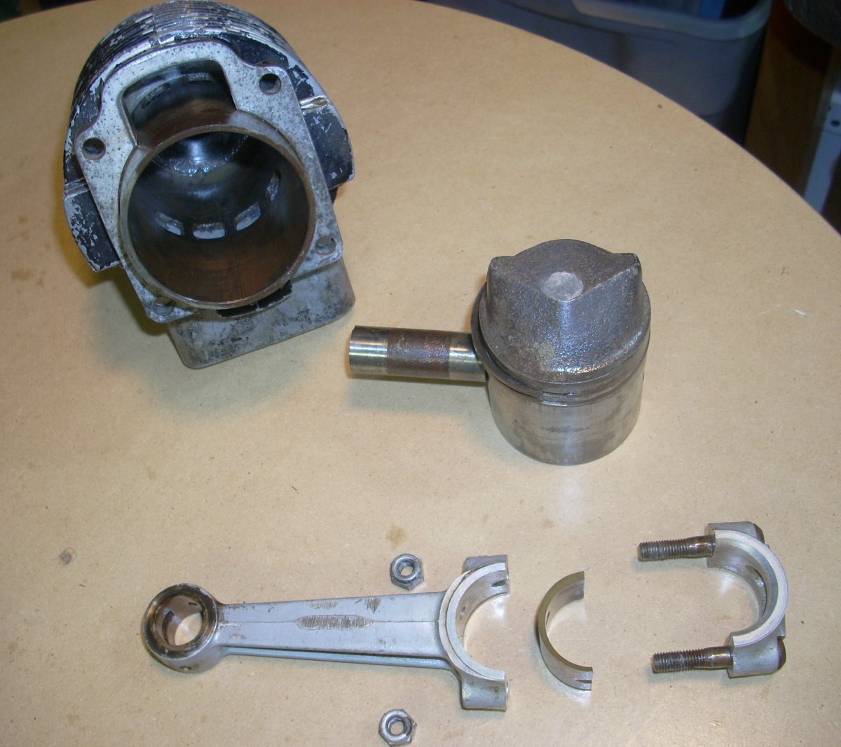 |
| Pic 9: Looking down the cylinder with the ram still in place. Rust and corrosion evident everywhere, particularly near the top of the cylinder sleeve near piston top dead center. | Pic 10: Pitted piston rings. | Pic 11: Cylinder, connecting rod, and piston. The cylinder, piston rings, and wrist pin are severely corroded, however the bronze bearing and the aluminum rod and cap are in serviceable condition. |
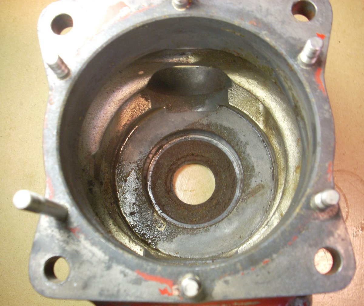
The nose section of these engines contain an oil/air seal pressed in from the front of the engine and a one piece thrust ball bearing pressed in from aft. Corrosion ate up the bearing, the steel seal retainer, and the adjoining area surrounding the bearing seat. (Pic 12) The original leather seals also tend to collect moisture, so the crankshaft had corrosion in this area as well. The crankcase and crankcase cover in the 0-15 series of drone engines are a magnesium/aluminum alloy and most if not all were plated with a very thin metallic plating to ward off corrosion (Pic 13).
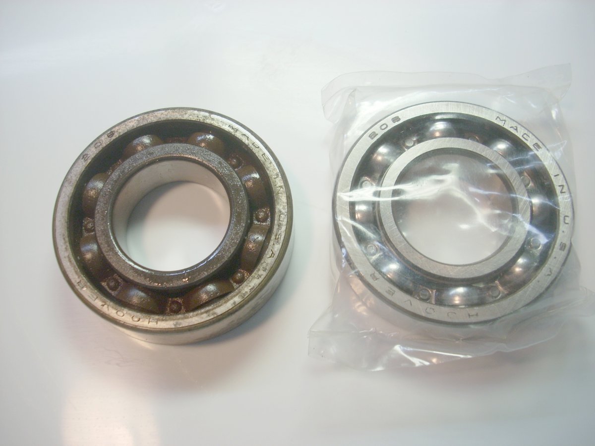
After cleaning the crankcase, I had to make a decision whether to treat the corrosion pits in the nose or let them be. I chose not to mess with the nasty chromic acid and instead would rely on abundant oiling and storage under low humidity for the rest of its life. A brand new, exact replacement Hoover 205 thrust bearing was found on eBay for $12, and a dimensionally correct modern oil seal, National 450189, for $6, also on eBay. (Pic 14, Pic 15) Fortunately, the new nose seal would ride on the relatively smooth, non-pitted area of the crankshaft.
 |
 |
 |
 |
| Pic 12: Viewed from aft looking forward into the crankcase, the corroded body of the nose seal is evident. The thrust bearing has been removed, and the nose seal is accessed from outside the crankcase. | Pic 13: The nose of the crankcase showing the recess where the nose seal is seated. Also note the silvery metallic plating on the aluminum/magnesium alloy crankcase. Yellow primer was evident on the back side of the red paint flecks. | Pic 14: Frozen thrust ball bearing on the left with exact replacement Hoover 205 bearing on the right. | Pic 15: Modern National 450189 substitute oil seal in place on the crankcase nose. |
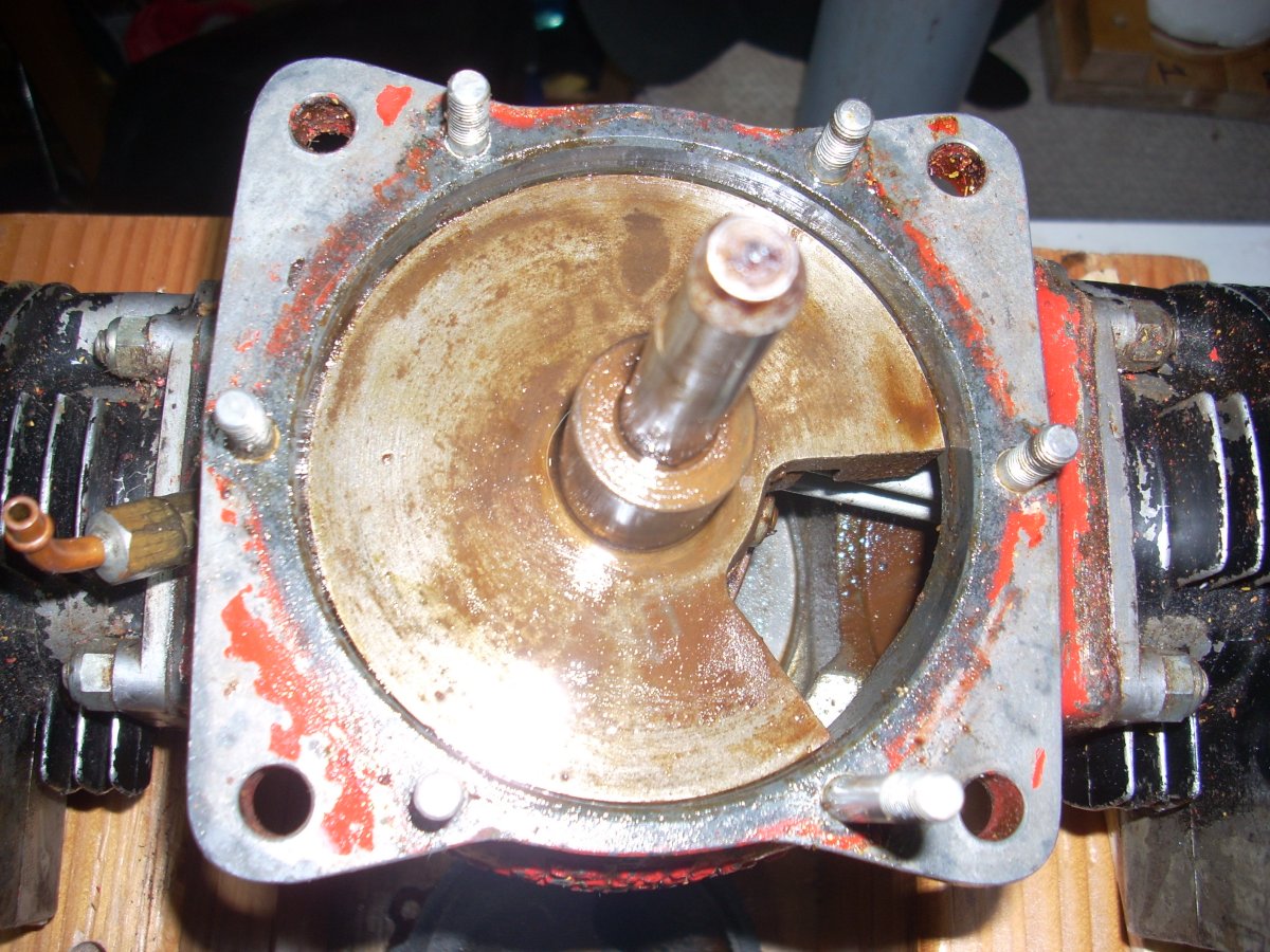
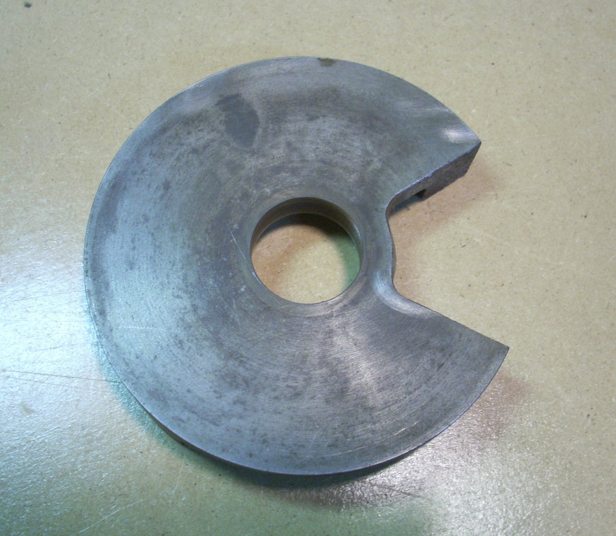
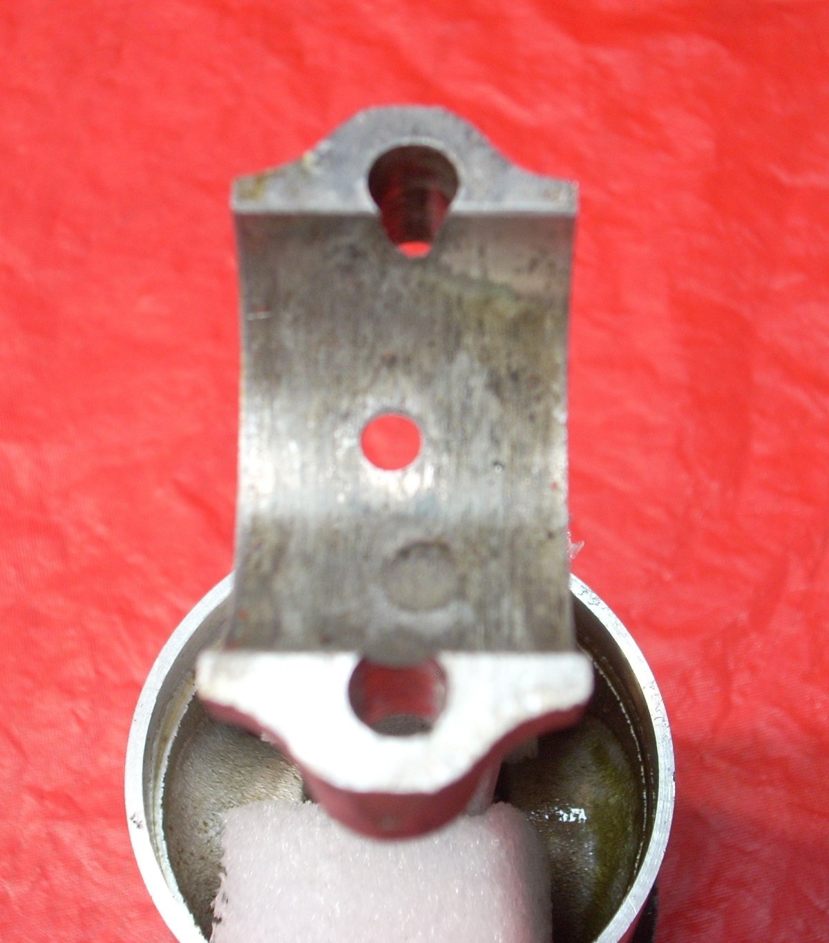
After removing the timer assembly and rear cover of the engine, the cast iron rotary valve, covered in sludge, was revealed. (Pic 16) Since the engine didn’t run when corroded, the rotary valve was in good condition. (Pic 17). This was fortunate as the machined aft face is tasked with forming a rotating air-tight seal against the rear cover for regulating air/fuel flows through the crankcase. The mating face of the rear cover showed some pitting, but due to its relatively large diameter and surface area, and short of having it professionally machined, I was willing to gamble that it would be functionally adequate. The bronze sleeve tail bearing was also found to be in good shape. (Pic 18) No rust was found under the rear leather seal, but there was a cut in the leather, so a modern Federal-Mogul 471472 rear seal was installed.
 |
 |
 |
| Pic 16: Rear cover removed showing the cast iron rotary valve. The pie-shaped cut out allows fuel/air mixture into the crankcase as the pistons rise in the cylinder bores, then rotates out of the way, sealing off the intake trunk while the crankcase is pressurized by the descending pistons for eventual fuel transfer into the cylinders. | Pic 17: Rotary valve was found in very good condition. Note the oblong gray spot at 11 o’clock where the oil lubrication port connecting the rotary valve interface with the bronze tail sleeve bearing was positioned during the corrosion years. This port provides lubrication to the bronze tail bearing and rear oil seal. | Pic 18: Rear cover of the 0-15 engine showing the carburetor flange at 6 o’clock and the intake port spanning 6 o’clock to 9 o’clock. The smooth face of the rotary valve runs up against the smooth face of the rear cover. Oblong oil port at 12 o’clock and the rear oil seal can be seen in the bore of the cover. Most of the metallic plating was absent from the rear cover. |
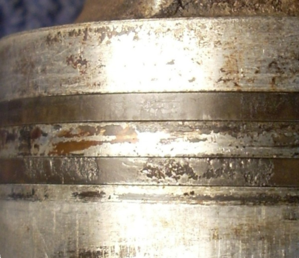
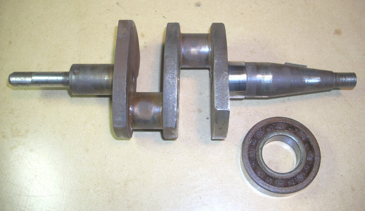
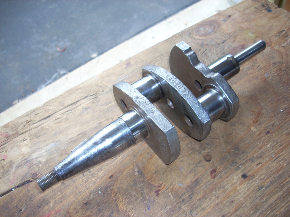
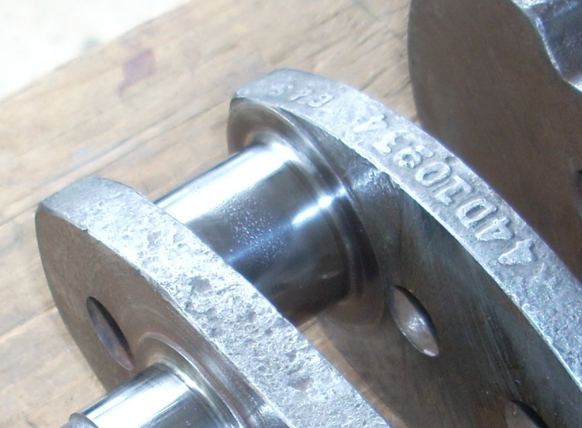
The crankshaft was a mess with corrosion on the cheeks, spots on the forward shaft where nose seal was seated against the crankshaft, and the areas where open portions of the bearing cap left the crankpin exposed. (Pic 19, Pic 20) The crankshaft journals of the forward ball bearing and the aft bronze sleeve bearing were in good condition as they were closely covered by oil-bearing surfaces.
 |
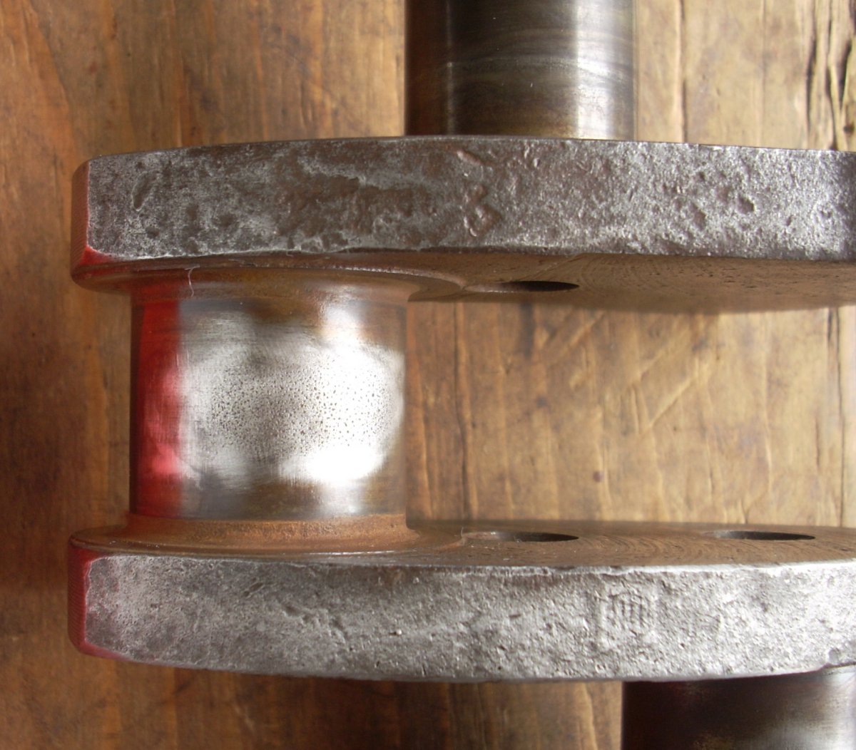 |
| Pic 19: Crankshaft as removed from the engine. Note the oval pitting on the crankpins where the rod cap holes left the metal open to the humidity as well as the pitting on the nose of the crankshaft. The well-preserved rod extending from the tail of the crankshaft is the "cam" for the timer. Note the relief where the rubbing block is allowed to drop, closing the points to energize the coil. | Pic 20: Preliminary file work to level the corroded pits on crankpin journal. |
I wire brushed the crank everywhere except the main bearing and crankpin surfaces. I used a fine Swiss pattern, double cut needle file to take the corrosion high spots off the crankpins followed by 1500 wet/dry paper on a popsicle stick. I then polished the crankpins with a long cotton cloth strip and jewelry polishing compound, worked like a shoe shine cloth looped around the journal. I cleaned the unblemished bearing surfaces with carburetor cleaner but otherwise left them untouched. (Pic 21, Pic 22) Obviously, this restoration is neither a precision nor restored-to-new endeavor as my goal was to return the original parts to a condition that would enable running. Shortcuts and certain mechanical gambles were accepted.
 |
 |
| Pic 21: Cleaned up crankshaft. Pitting on the nose of the crankshaft remained a concern, and the replacement nose seal was selected so that it would run on the least damaged circumference of the crankshaft. | Pic 22: Pitted crankpin after refurbishment with files, 1500 wet/dry sandpaper, and polishing. |
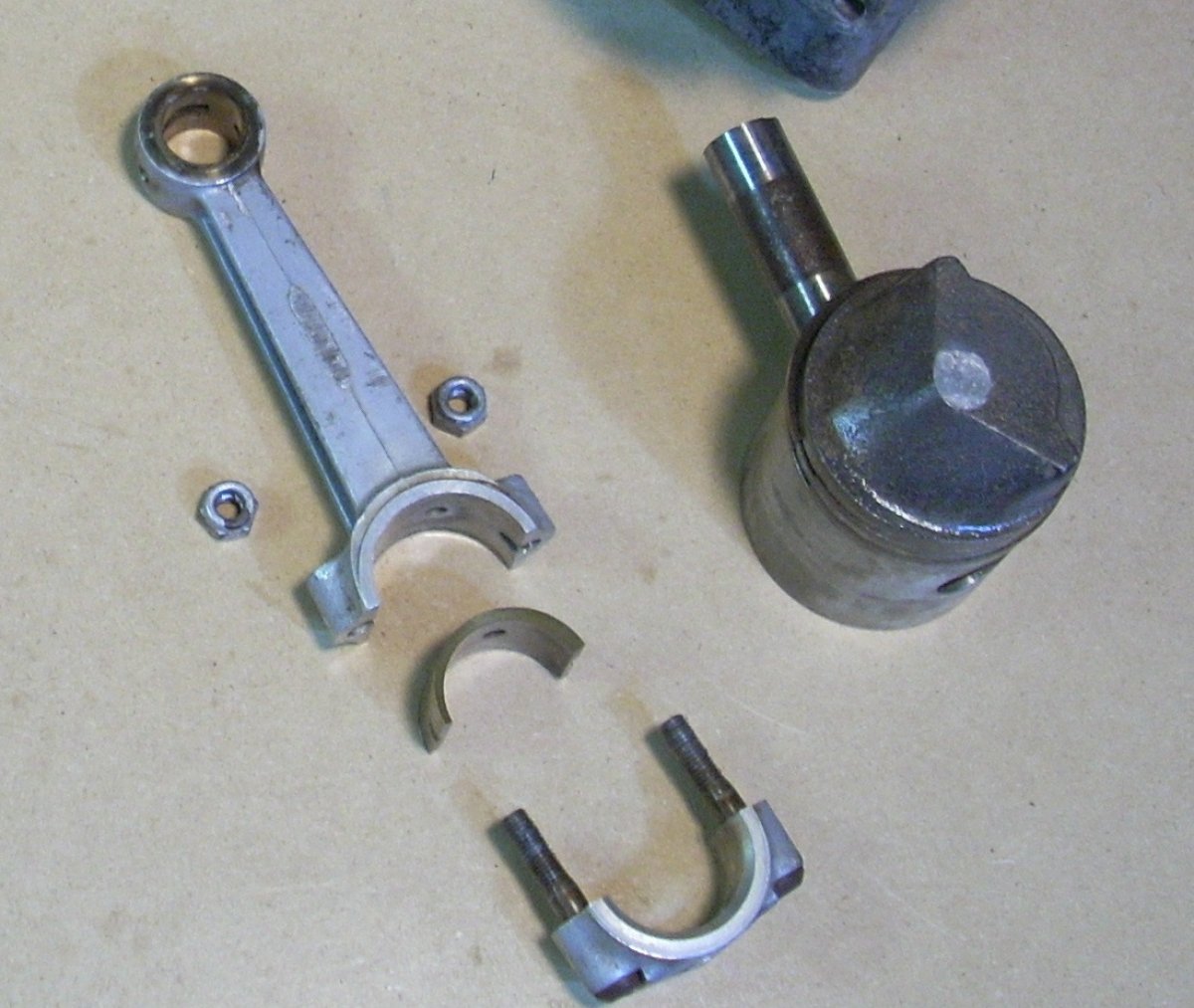
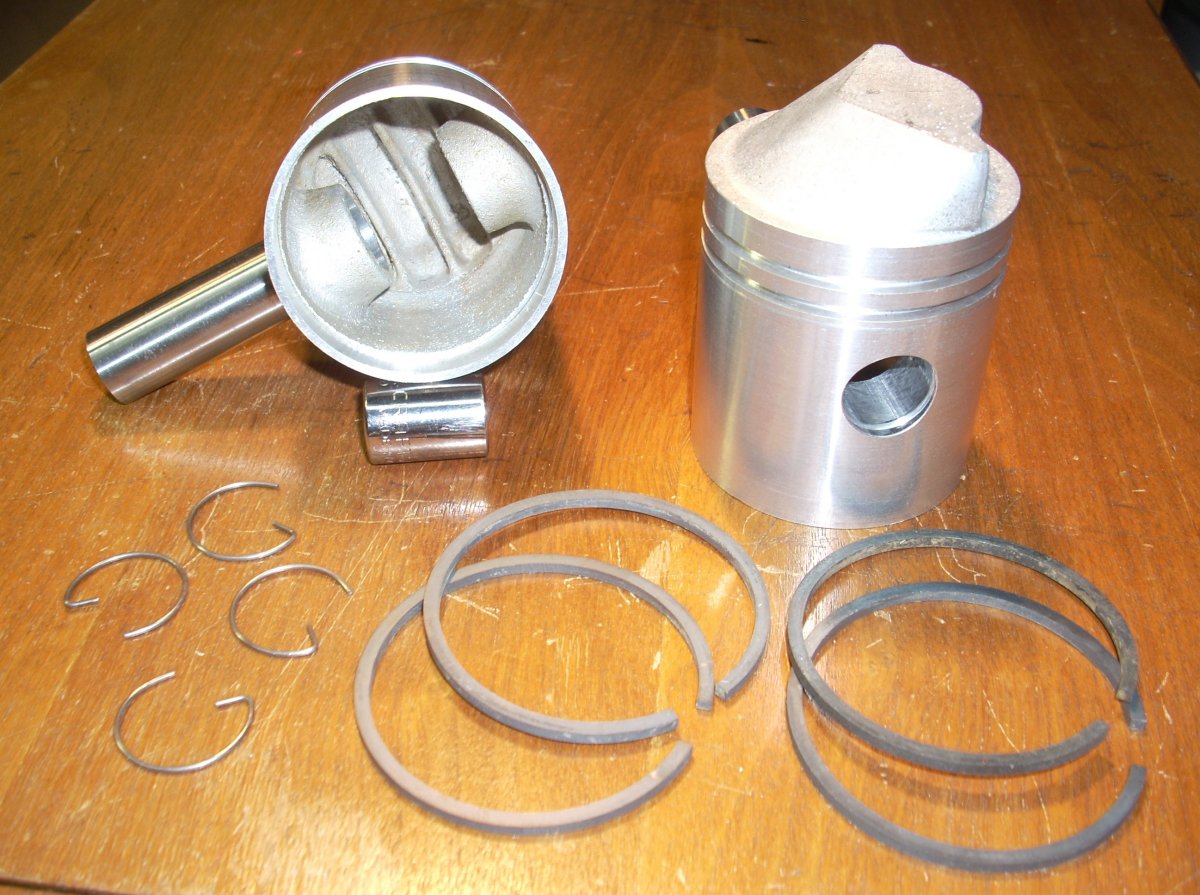
The piston rings and wrist pins were pitted and I was lucky enough to acquire NOS pistons, rings, and wrist pins from a fellow collector. (Pic 23, Pic 24) The rods and bronze half shell rod bearings were cleaned and reused in the engine. Curiously, the bronze half shell bearing was incorrectly installed in the big end of one of the rods, thus the oil hole did not align with the oil access hole in the big end of the rod. (Pic 24a). Whether this happened at the factory during assembly or some later time is unknown. Also, the standard AN365-428 fiber lock nuts specified for the rod caps were replaced with low-profile AN364-428 fiber lock nuts and the use of a washer on the ill-fitting replacement rod. (Pic 24b) More mysteries!
You might question the heat resistance of the fiber lock nuts to secure the rod caps, but remember the crankcase is pumping relatively cool air/fuel mixture through it every stroke. Crankcase temperatures did not exceed 150° F in the 50 hour type test of a similar engine.
 |
 |
 |
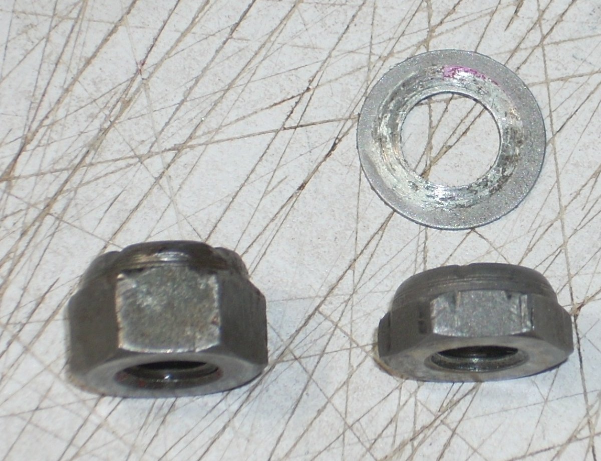 |
| Pic 23: Aluminum connecting rod with bronze bushing in the little end, removable bronze half shell plain bearing in the big end. Note the large oval hole in the bearing cap that allows oil mist to access the bearing but also let moisture access the crankpin while in storage. Similarly, the piston wrist pin is corroded due to moisture access through a lubricating slot on the little end and bearing of the connecting rod. | Pic 24: New old stock pistons, rings, and wrist pins. | Pic 24a: Bearing seat on piston side of the big end of the connecting rod. Note the gray oxidation circle where the hole in the bearing resided when found. The hole in the bearing should have been aligned with the hole in the connecting rod to provide oiling to the crankpin. | Pic 24b: The stock AN365-428 fiber lock nut shown on left should have been used to secure the rod cap. Instead, the shorter AN364-428 fiber locks nut and a washer were found on the potential replacement rod. |
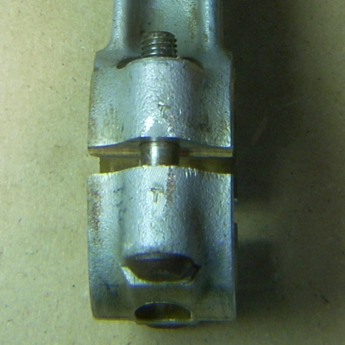
The tolerances on the big end bronze bearing in the rods are rather large (0.015" limit), and indeed one big end, while within specs, had a “knock” when the piston went over TDC. (Pic 25, Pic 26) I hoped this would go away once the piston was under constant loading during running. I borrowed what I thought was a serviceable, stamp-matched rod, bearing, and cap from a fellow collector, but when I installed it, it gripped the crankpin journal immovably tight. It was then that I learned not all individual parts or even matched assemblies are interchangeable in these engines.
The die cast cylinders, while externally-perfect, had pitted cylinder liners that barely held any compression. I tried to run the engine on these pitted cylinder sleeves, but it would only sputter along for two seconds, spitting fuel mist backwards out of the carburetor. (Pic 27)
 |
 |
 |
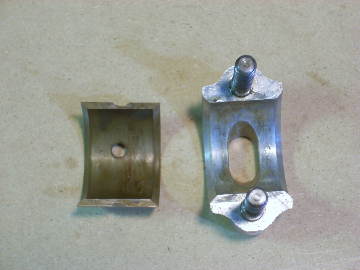
| Pic 25: Half shell big end bronze bearing on the left and connecting rod cap on the right. Connecting rod cap carries no load in 2 stroke engines and thus requires no specialized bearing surface. | Pic 26: Connecting rods, connecting rod bearings, and connecting rod cap are bored as a unit and thus precision-matched. Rod and cap pair is stamped "T" in this example. | Pic 27: Even after honing, severe pitting near piston top dead center rendered this cylinder useless for running. |
I was able to acquire a used, die cast, rectangular port O-15-3 cylinder with exhaust stack damage from a fellow collector and sold my pitted cylinders to a friend for static display on one of his engines. And I traded parts with another collector to get a sand cast O-15-3 cylinder with round ports. I fixed the deformed exhaust stack corner with JB Weld and a sheet aluminum backing plate. (Pic 28) The result was a O-15-3 with identical cylinder part numbers on each side of the engine and solid cold compression values of 42 psi on the port side and 52 psi starboard.
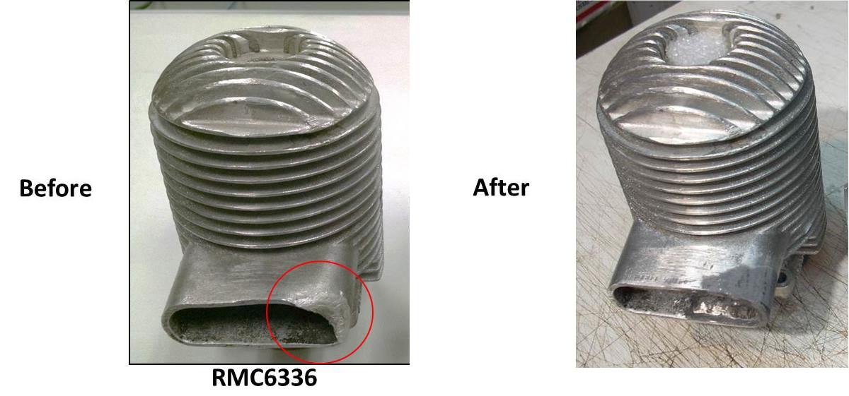 |
| Pic 28: Corner of the exhaust stack was crushed and abraded. Metal was brittle and broke when I tried to straighten it. So I filed the broken bits, mixed the shavings into the JB Weld, and used a 1/32nd thick aluminum backing plate on the inside of the stack to make the repair. Black paint hides everything. |
The rod cap nuts and all of the external case stud nuts were replaced with new stainless MS20365 fiber lock nuts, and I used aircraft grade nuts and bolts on the engine, propeller, and engine mount. The four engine gaskets and one carburetor gasket were traced onto 1/32nd inch thick rubberized gray fiber automotive gasket sheet and cut out with scissors and hole punch.
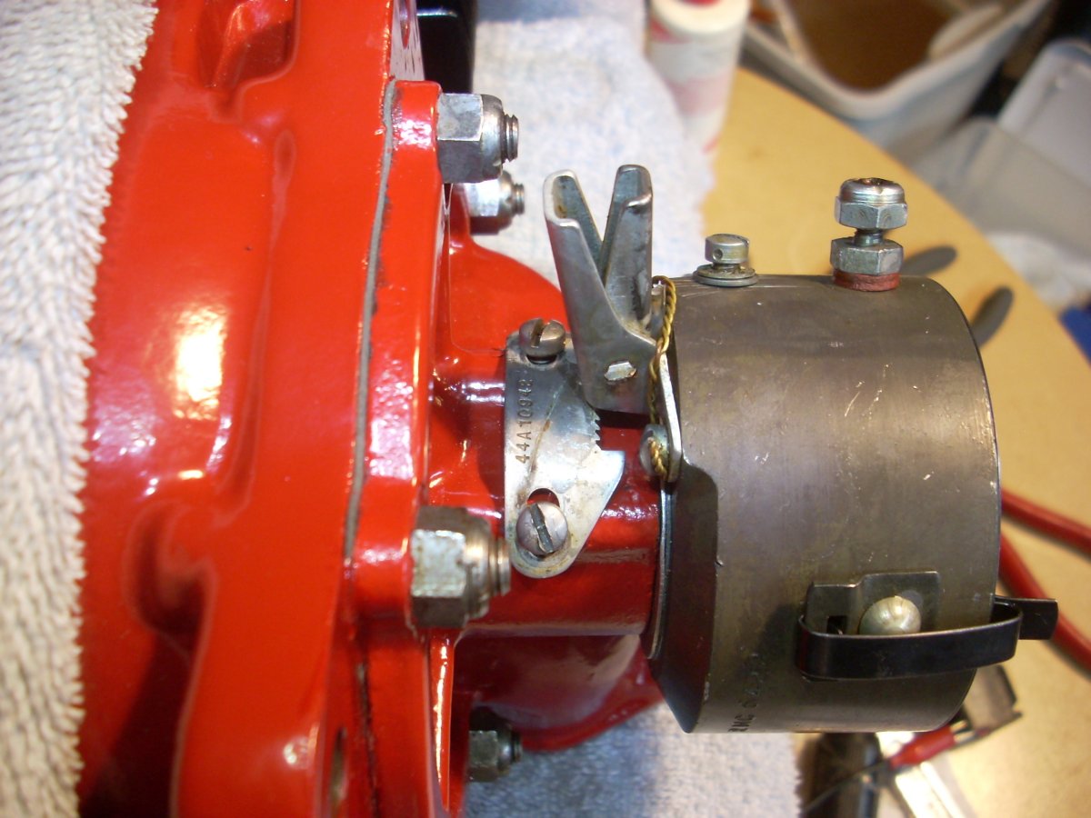
The timer was packed in grease when I got the engine so it was nearest to brand new of all the parts on the Righter. (Pic 29, Pic 30)
The carburetor was dirty but complete and is as simple a carburetor as you can find. (Pic 30b) The engine was designed to run wide open until it died from lack of fuel or was killed outright by gunfire, so the carb had no throttle. The seat for the needle valve was found upside down from the correct position. A scrap carbon rod held in place by a round sleeve trapped in a keyhole bracket was attached to the spring-loaded choke so that full on or full off could be selected from far behind the prop arc. (Pic 31)
 |
 |
|
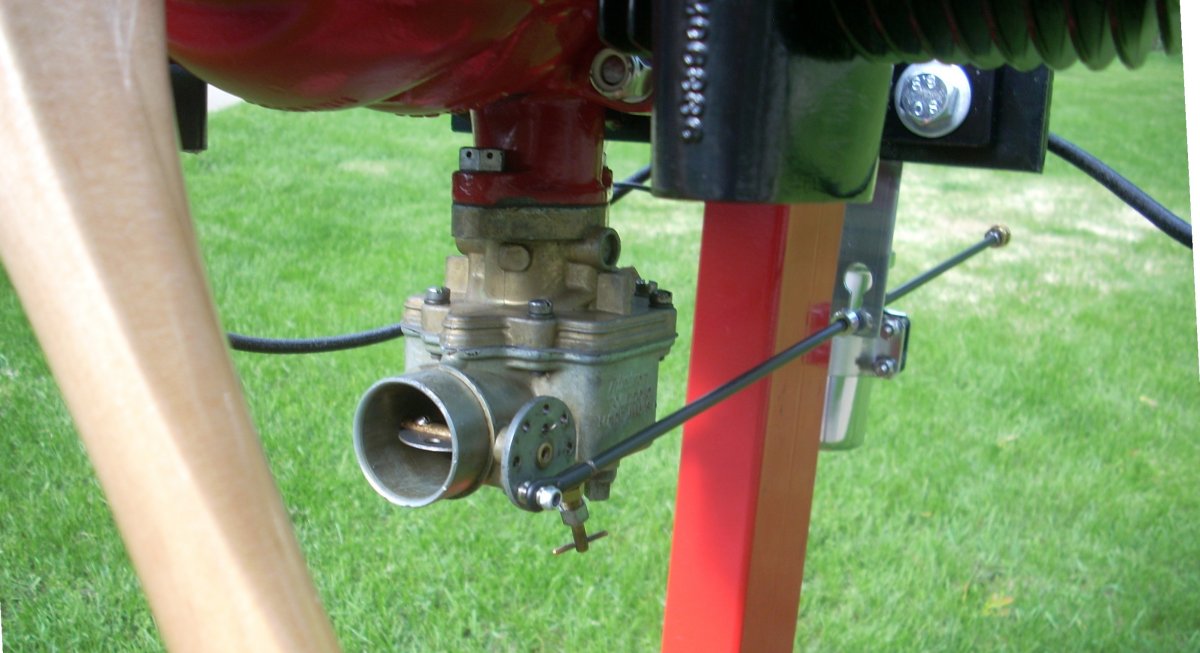 |
| Pic 29: Ignition time assembly. Center rod is an "inverse cam" such that the points remain open for the majority of a revolution, then the rubbing block drops into the relief on the rod, closing the points and energizing the coil. As the rod rotates further, the block is forced out of the depression, opening the breaker points and firing the coil. Condenser on the right and insulated lead-out post located at 1 o’clock. | Pic 30: Side view of completed timer assembly on rear of engine. Lever at top has a spring loaded pawl that engages the toothed rack on the crankcase to hold the timer in the selected position. The entire cylindrical timer assembly is mounted on the engine centerline using a spring washer and keyhole grooves that provide 30° of rotation to advance the spark timing. | Pic 30b: Schematic of the simple Tillotson YC3A carburetor. Mixture needle is located at the lower rear of the carburetor bowl. | Pic 31: The choke is spring loaded to maintain it open. A carbon rod with an adjustable stop resides in a keyhole slot to hold the choke closed during priming. |
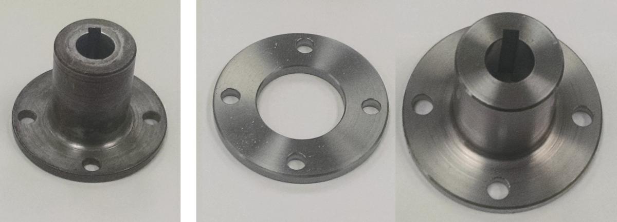
The engine lacked a propeller hub, flange, and propeller. A fellow collector had some new hubs and flanges machined from stainless steel, so I kept sending him drone parts and materials until I earned one of his hubs in trade. (Pic 32)
I had acquired an original 30 x 30 propeller off of eBay ($60) to use as a pattern to make a new propeller for running. As chronicled in my previous restorations, making a drone prop is more time consuming than difficult. (Pic 33, Pic 34, Pic 35) The two most important prop things are that the left side blade matches the right side blade in contour and planform, and that the prop is balanced in all axes. A pin-type contour gauge guides the former, and a lawnmower blade balancer the latter. Made from two laminations of less than 10% grain runout, knot-free white birch glued with Cascophen, I left the prop about 1/8" thicker than the original for safety and durability. The hub and propeller are indexed so that TDC occurs with the propeller in the vertical position.
 |
 |
 |
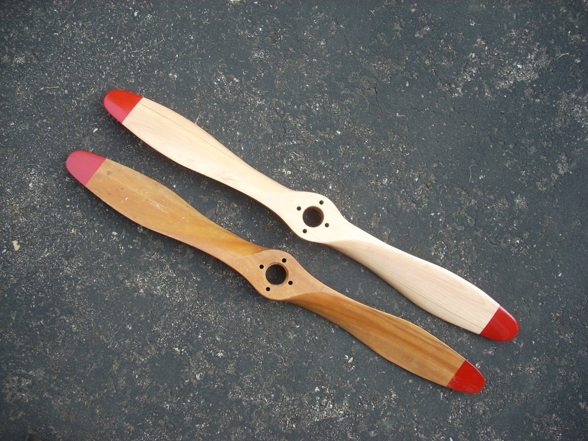 |
| Pic 32: Original cadmium plated steel propeller hub shown left of the machined stainless steel flange and hub. Hub has a 15° taper bore and a keyway. | Pic 33: Original propeller planform is traced on the laminated and drilled white birch blank. It will be cut out with scroll saw and trued with a vertical sander. | Pic 34: An original propeller was used to generate the red templates at regular intervals along the span of the propeller blade. The templates will guide the shaping of the propeller. | Pic 35: New propeller shown above an original 30 x 30 inch propeller. |
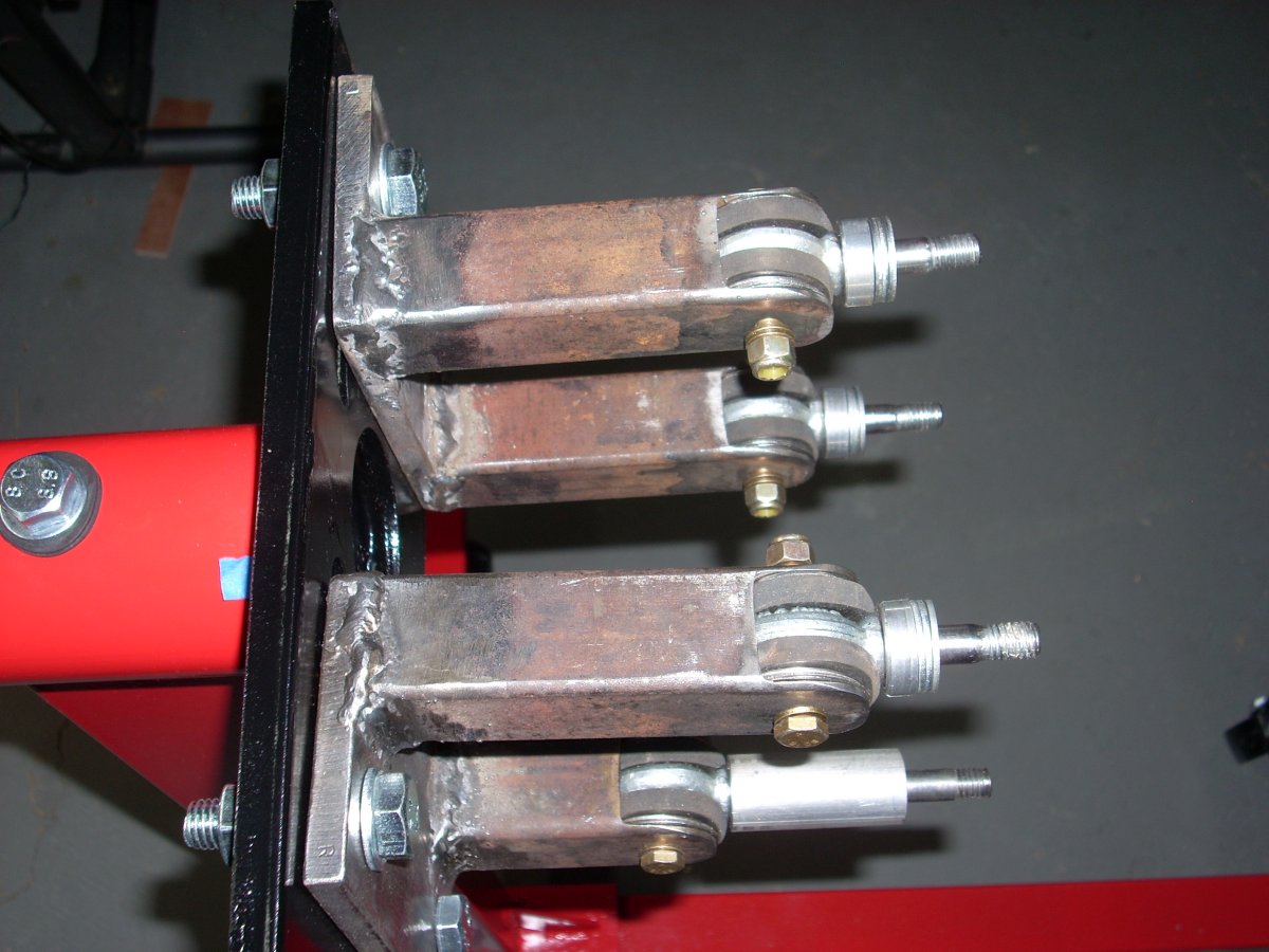
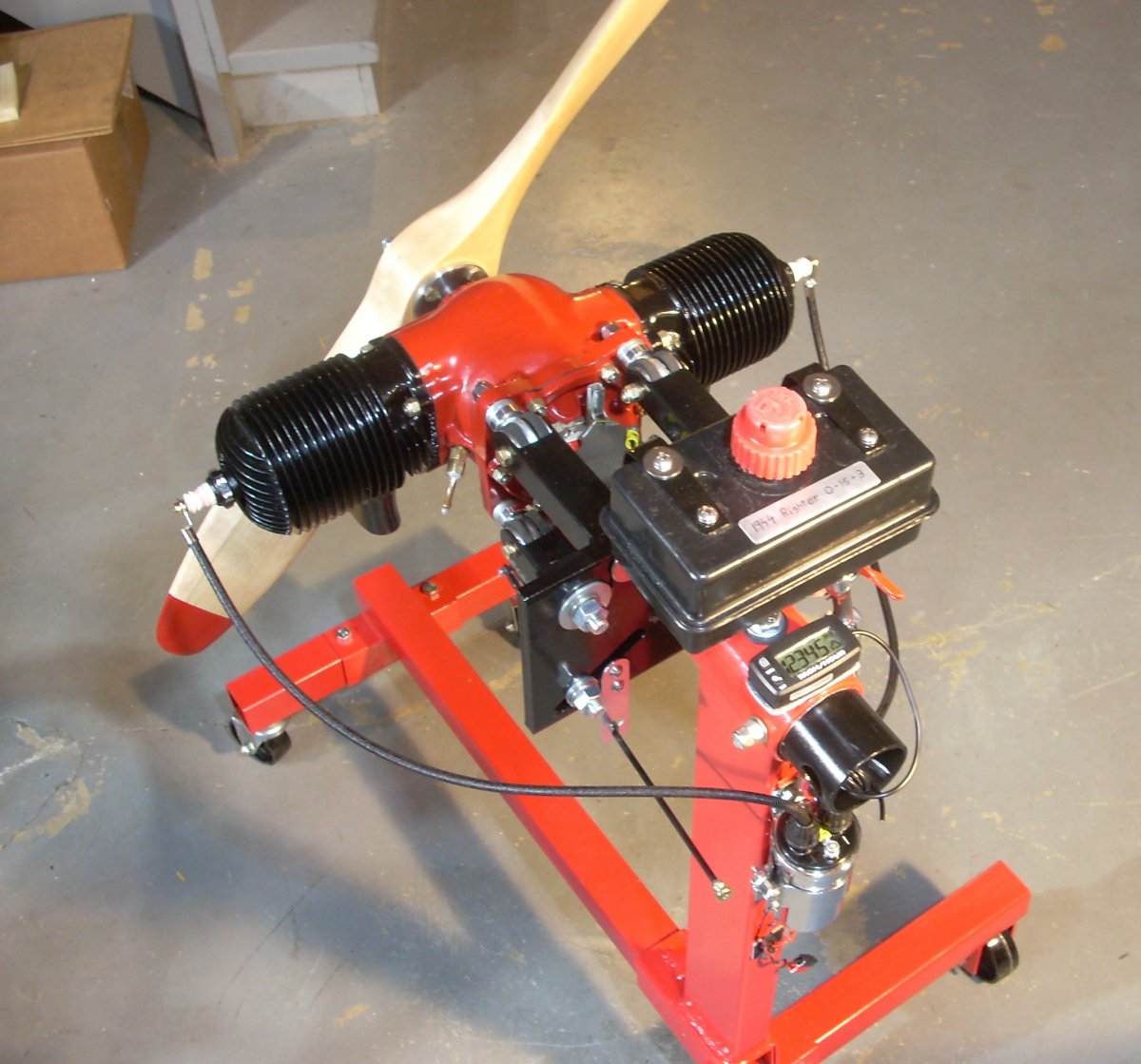
The running stand started out as a $65, half-ton capacity engine rebuild stand from Harbor Freight. A friend kindly welded up an engine mount and machined concave washers to mate the forged eyebolts (Farm and Fleet) to clevises ground out of the 14 gauge (0.083" wall), 1.25" square steel tubing. The center of the eyebolt was lined with bushings of reinforced fuel line with a central steel spacer to complete the isolation mount assembly. (Pic 36) These engines vibrate quite a bit, and hard mounting them to a running stand tempts broken metal or disintegrating propellers. A used 40 ounce plastic Toro fuel tank off eBay ($12), good for 9 minutes of running, was bolted to metal straps giving 11" of pressure head between a full tank and the carburetor. An inline, clear-body fuel filter helps confirm fuel flow. The height of the fuel tank / running stand was determined by the ability of the complete engine stand to fit through the hatch of my wife’s Honda Odyssey min-van. (Pic 37)
 |
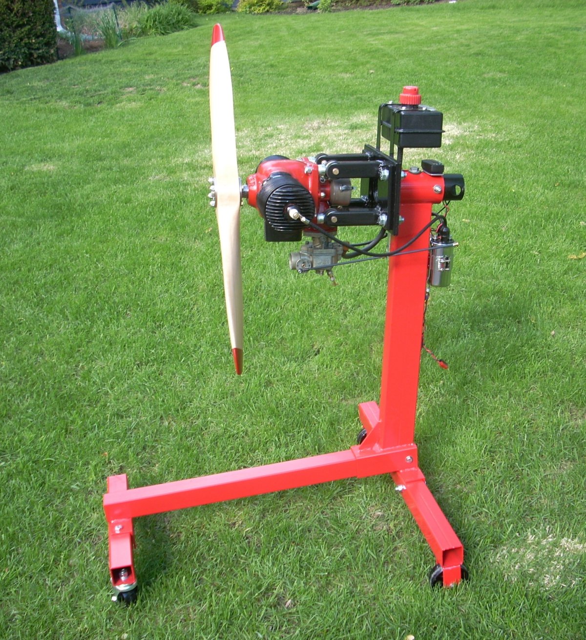 |
| Pic 36: Engine mounts fabricated from square steel tube welded to a backing plate. Clevises were ground out of the ends. Forged eyebolts with rubber dampeners in the bore mate the engine to the running stand. The aluminum spacer at the bottom of the photograph was required to provide clearance between the mount arm and the intake trunk. | Pic 37: Side view of running stand. Height is 42 inches. |
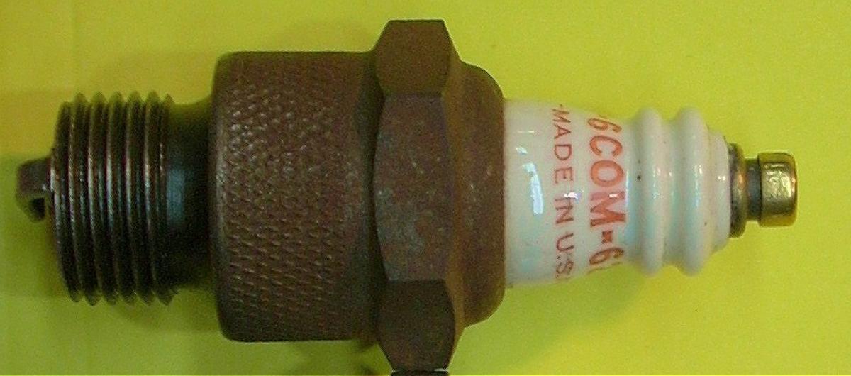
The ignition system consists of a 4 amp-hour, 12 volt battery, aftermarket 12 volt motorcycle dual coil, original breaker points, condenser, and an electrical safety cut out made from a fuse holder connected by a trailer linchpin on a safety tether. (Pic 38, Pic 39) The dual coil pulls 0.7 amps when the points are closed, but in this engine the points are closed for a short period of time each revolution, so a 4 or 5 minute run uses only 400 milliamp hours of power. Original Champion 6-COM-62 plugs ($12 each; eBay) light the fire. (Pic 40, Pic 41) The specified fuel-to-oil ratio is 6 to 1, and I use ethanol-free 93 octane gasoline with modern two stroke oil at the specified ratio.
 |
 |
 |
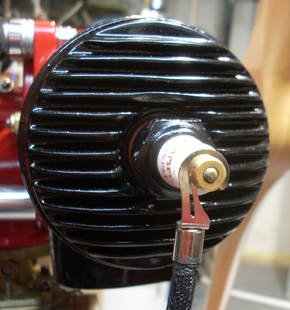 |
| Pic 38: Electrical diagram for the O-15-3 engine. | Pic 39: Ignition arming / emergency cut out switch armed with removable linchpin. | Pic 40: Hard-to-find "aviation style" Champion 6-COM-62 spark plug. Note the integral slotted terminal for the spark plug lead. | Pic 41: Spring loaded Rajah connector allows freedom of motion but excellent contact on the plug. |
For running the engine, the small diameter steel wheels on the stand are stomped down into the ground and three or four 40 pound sand bags stabilize the stand in place.
As shown in the video link, the engine starts fairly easily. Disarm the ignition, fuel on, open the mixture needle valve 2.5 to 3 turns, timer set to fully retarded (spark @ TDC), full choke, confirm ignition is disarmed, then several cold pulls to get fuel to the cylinders. Arm the ignition system by installing the pin, and flip the prop over briskly in such a manner that momentum carries your hand and body away from the propeller arc. Once the engine starts, walk a wide path around the prop, ease open the choke, and turn in the needle to lean the mixture towards a two stroke whine.
The engine is unable to accelerate beyond 2,200 rpm without rotating the timer to advance the ignition timing, so the timer, like the choke, can function as a crude throttle. For high speed, advance the timer by the lever to the maximum 30° BTDC setting, lean the mixture to maximum rpm, then richen the mixture with one eight of a turn out. This engine has briefly achieved 3,520 rpm, which isn’t too bad considering the thicker prop, aged cylinders, and pitted heritage. And after 8 minutes of running, the JB Weld repair on the port exhaust stack remains in place. (Pic 42)
The manual specifies a stable 3,800 rpm before launch, but 75 years after it was built, including some number of years in a humid environment, I couldn’t be happier. (Pic 43, Pic 44, Pic 45)
 |
 |
 |
 |
| Pic 42: JB Weld repair has survived eight minutes of running without withering or cracking. Fortunately, the repair is directly in the wind off of the prop which likely helps to keep the temperature down. | Pic 43: Starboard side of stand showing glass-bodied fuel filter and inline stopcock. | Pic 44: Driver’s-eye view of the running stand. Gas tank suspended from steel straps, choke rod on the left side, digital tachometer fastened to the trunion, and dual coil is bolted to the rear of the vertical support. | Pic 45: Glamor shot. Righter O-15-3 engine data plates were not stamped with a serial number or manufacture date. McCulloch-built O-15-3 engine data plates had a serial number, but no date of manufacture. |
Video Links
Righter O-15-3 First Run Wartime OQ-3 Drone in Action
Documents and Sources
AN 28 10C-2, Handbook of Instructions with Parts Catalog, Radio Controlled Airplane Target AAF Type OQ-2, Navy Type TDD-2, 25-September-1944
50 Years of Target Drone Aircraft, Richard A. Botzum, Northrop Corporation, 1985
Send mail to
![]() with questions or comments about this web site.
with questions or comments about this web site.
![]()