An Incomplete History of the
Hamilton Standard Super-Hydromatic Propeller
Part 1: Overview
by Tom Fey
Published 11 Jun 2018; Revised 27 Oct 2023

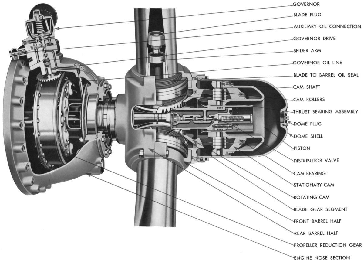
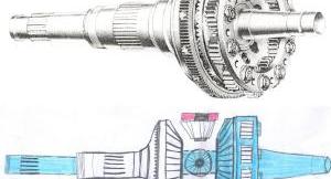
Fig. 1. The world-class Hamilton Standard Hydromatic propeller. The central dome houses a piston, fixed cam, and rotating cam that use hydraulic power to rotate the propellers blades on their own axis to enable constant speed, feathering, and reversing. |
In the years leading up to WWII, the Hamilton Standard Division of United Aircraft Corporation, based in Windsor Locks, CT was the leading producer of hydraulic constant speed propellers. Unveiled in 1938, the Hamilton Standard Hydromatic constant speed propeller was a world-leading technology that used high pressure oil from the propeller governor, ported through the bore of the propeller shaft, to drive a piston in the central dome of the propeller. This piston drove rollers engaged in a rotating cam inside the dome to transform axial movement of the piston into rotary motion of the blade shanks. The bottom of the rotating cam had gear teeth that engaged the segment gears at the base of the propeller blades, thereby changing the pitch of the propeller blades (Fig. 1). The development of the Hydromatic propeller is beyond the scope of this work, however, in the same year they unveiled the Hydromatic, Hamilton Standard initiated the design and development of the successor to the Hydromatic, which would be called the Super-Hydromatic. |
Background
What features were lacking in the Hydromatic that spurred the development of Super-Hydromatic? The dependence of the Hydromatic on engine oil was certainly one factor, as loss of engine oil would affect the controllability of the prop, including feathering, resulting in engine overspeed, monumental drag from the windmilling prop, and the catastrophic departure of the propeller blades, propeller assembly, or entire engine from the aircraft.
A second consideration was the rate of pitch change. For military pilots, whether fighter aircraft, bombers, or transports, the faster the pitch change the better. Rapid pitch change assured that a fighter engine would not overspeed in rapid diving maneuvers, and for bombers and transports, that the propeller on a failing engine could be rapidly feathered before aircraft controllability suffered an unrecoverable disturbance. The Super-Hydromatic was designed to have a remarkable 35 degrees per second rate of pitch change compared to the single digit pitch change rates of propellers then in service.
In addition to the reversing of blade pitch to shorten landing rolls, rapid pitch change would open up a new world of pitch reversal in maneuvering flight, or to create drag to slow an aircraft during dive bombing.
As propellers grew larger they grew heavier as well. It was hoped that the innovative design of the Super-Hydromatic as well as hollow steel blades may significantly reduce the weight of the Super-Hydromatic compared to the Hydromatic or propellers from competitors by at least 50 pounds, or around 12% of a typical fighter propeller weight.
And yet another advantage of a new propeller design would be the provision of dual rotation propellers. As engine horsepower increased from say 1,100 horsepower at the start of WWII, to 2,000 horsepower mid-war, and the prospect for 3,000 to 4,000 horsepower piston engines by war end, dual rotation propellers had the potential to negate the detrimental physics (torque; blade loadings; hub loadings) that heavy, large diameter propellers were already having on the controllability of single engine, tail dragger aircraft during take-off and carrier landing. Large propellers also significantly impacted airframe design, particularly landing gear length, strength, and geometry, to keep propellers from hitting the runway or carrier deck during normal operations.
By virtue of their contra-rotating design, dual rotation propellers eliminate airframe yawing on the ground, or rolling when in flight, due to engine torque when power is applied to an engine with a single rotation unit. These torque effects can be extreme at low airspeeds such as take-off and carrier approach because of the low effectiveness of the flight controls in those flight regimes. In addition, the dual rotation propeller offers much greater blade area to absorb horsepower in a diameter that provides reasonable blade loading and avoids ground contact, has the potential to recover some the slipstream swirl energy off the leading blade set, and maintains subsonic propeller tip speeds.
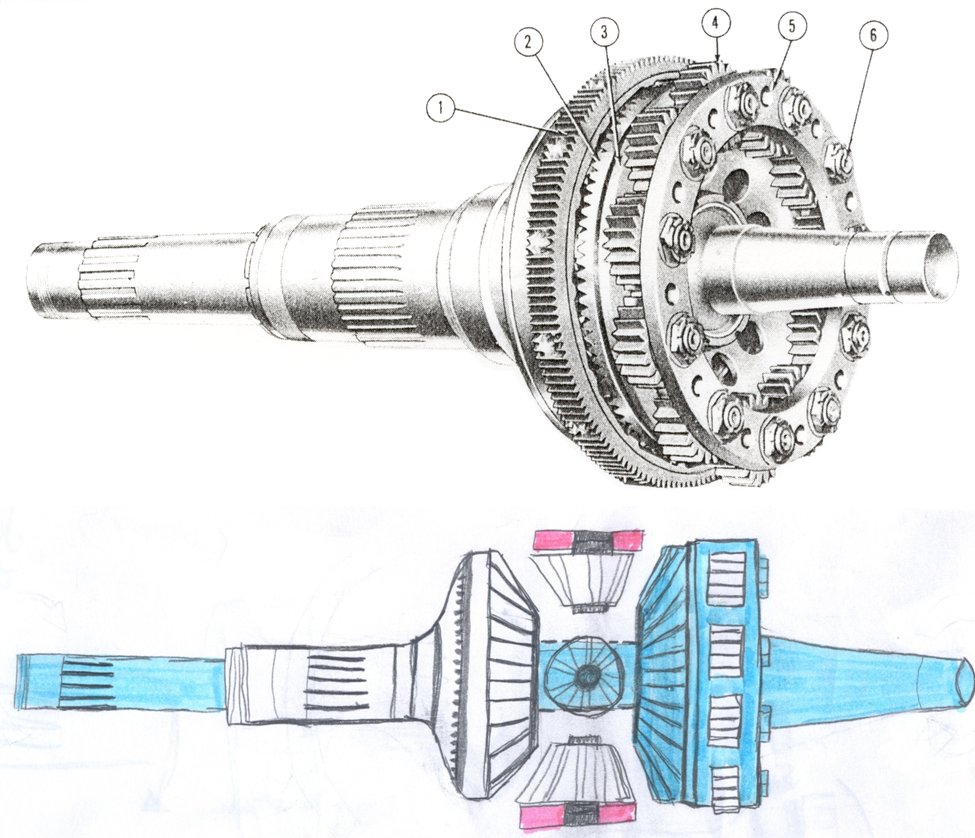
The downside of dual rotation propellers is weight, complexity, noise, vibration, additional gearing or gearboxes, and the necessity to produce blades of opposite pitch. There are several gearbox designs to accomplish concentric, contra-rotating propeller shafts, but the most common design used for the dual rotation Super-Hydromatic is the typical planetary reduction with a Farman gear set driving the inboard propeller shaft (Fig. 1a).
 |
 |
| Fig. 1a. The compact and efficient Pratt & Whitney dual rotation propeller gear set. A Farman gear set has been added to the front face of the typical planetary gear reduction system that reverses the rotation direction of the inboard propeller shaft but maintains the same reduction ratio as the outboard propeller shaft. |
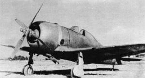
Fig. 2. The only known photograph of the Nakajima Ki-44-1 Type 2 fighter with the Sumitomo Pe-7 contra-rotating propeller. It appears that linkages from the counterweights are slaved together via a translation bearing. Mechanical and flight performance are unknown. |
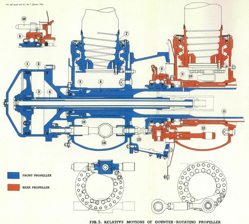
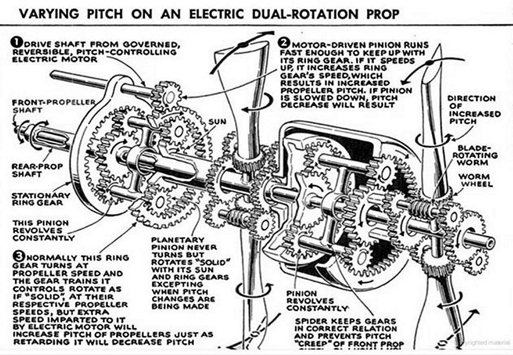
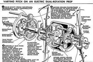
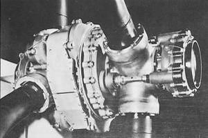
The counter-weighted Hamilton Standard propeller could be adapted to dual rotation through the use of a translation bearing, and this was attempted with little success by licensee Sumitomo in Japan during WWII (Fig. 2). Both de Havilland and Rotol developed hydraulically-actuated contra-rotating propellers via translation bearings, but this design did not address the engine oil supply and rapid pitch change issues. Lubricating the highly loaded translation bearings was a significant challenge (Figs. 3, 4). Curtiss Electric developed both coaxial (each propeller on the same axis powered and controlled by a separate governor and engine) as well as contra-rotating designs during WWII, but the former was used only on one aircraft, and the latter was burdened, at that time, by mechanical complexity, heavy weight, and slow pitch change (Figs. 5, 5a).
 |
 |
 |
 |
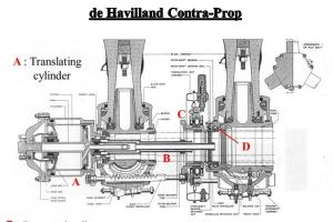
| Fig. 3. The hydraulic de Havilland contra-rotating propeller uses boosted engine oil to drive a central ram with toothed racks to tie into the translation bearing. Used with long success on the AVRO Shackleton patrol bomber. Translation bearing is lubed by oil injected into the bearing at scheduled rpm changes during operation. |
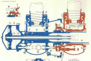
Fig. 4. The hydraulic Rotol 35 degree contra-rotating propeller uses boosted engine oil to drive central ram and linkages to tie into the translation bearing. The translation bearing is lubricated by grease. Used in the F.47 Seafire. |
Fig. 5. The Curtiss Electric contra-rotating propeller that used a donut-shaped electric motor and Stanley/VDM type gearing to change the propeller pitch. The gearing ran in oil and/or grease. |
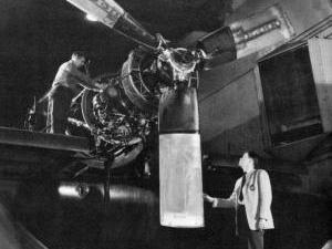
Fig. 5a. The six-blade Curtiss Electric contra-rotating propeller. |
The remaining American player in dual rotation propellers was Aeroproducts who filed a patent in October of 1940 for a dual rotation propeller design that featured an independent, self-contained oil supply in each of the blade sets, no translation bearings, splined hydraulic actuators in each hollow blade root, and relatively rapid pitch change (Fig. 6). While I can't establish exactly when Aeroproducts and Hamilton Standard began design work on their respective dual rotation propellers, or how much each company knew about their competitor's design, the concepts of the propeller are similar, but executed in very different manners.
Super-Hydromatic propellers were produced in both single rotation and dual rotation configurations. The Chief Engineer at Hamilton Standard for the Super-Hydromatic program was Carl F. Baker.
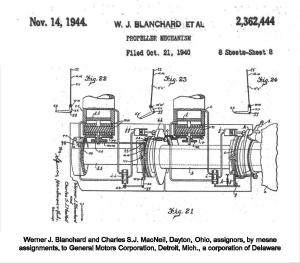 |
| Fig. 6. The Aeroproducts dual rotation propeller schematic in the patent document. Both components contained their own pumps and oil supply. The inboard unit was controlled by a bell crank that adjusted a centrifugal governor in the spinning regulator. A mechanical signal was sent from the inboard regulator to the outboard regulator to adjust a servo valve that controlled pitch in the outboard component. Used in the Fisher XP-75 and P-75A. |
Part 2: Mechanical Descriptions
Part 3: Aircraft Applications
Part 4: Super-Hydromatic Propeller Timeline
Conclusion
Great effort was expended by Hamilton Standard to develop a technologically advanced propeller system adaptable to the ever more powerful piston engine of the middle 1940s with an eye towards the turbopropeller engine of the encroaching future. Turbine engines are most efficient while running at 100% design speed, with power being adjusted via fuel flow, and RPM controlled primarily by propeller pitch. Maintaining a propeller speed within a few percent of design speed during power changes that can involve the rapid application of thousands of horsepower is a daunting task, yet rapid pitch change is a key element to controlling this power.
From the available information it is clear the Super-Hydromatic design, even after eight years of work, struggled with keeping operating fluid in the Propeller Control Unit as well as the pump bodies. Real-time monitoring of fluid levels, or in-flight replenishment, was not a feature of the Super-Hydromatic, and loss of fluid from either component in flight would be detected likely too late for effective remedial action. The Super-Hydromatic design required a large number of high pressure seals and featured multiple precision rolling elements that had to be to be secured and lubricated, all while managing 3,000 psi working pressure and 3,000 horsepower. Dependability, especially in dual rotation propeller or high horsepower application, is essential for safe operation.
A curiosity lost to time is that the dual rotation Super-Hydromatic propeller used in the XTB2D-1, XF-11, and XB-35 all had fore propeller diameters smaller than the aft propeller diameters. This is contrary to many dual rotation propeller installations, such as the AVRO Shackleton, where the aft propellers were of slightly smaller diameter than the fore propellers in attempt to minimize the stress and vibration of the fore propeller tip vortices from impacting the tips of the aft propeller.
Regarding the potential of reversing pitch during flight in a single engine aircraft, this was successfully demonstrated by a Curtiss-Electric single rotation propeller. Propeller reversing in flight was never attempted by the Super-Hydromatic as the rubber pellet-filled, hollow steel blades were not designed for in-flight reverse loading and would require an internal spar to do so. The use of flat pitch / high drag configuration during approach and after landing was performed by the Super-Hydromatic in the Ryan XF2R-1 dual powered experimental fighter, but reverse pitch was not attempted.
I have yet to find information regarding the weight of the installed Super-Hydromatic propellers, but as a period frame of reference, the six blades, thirteen foot diameter Aeroproducts AD7562 dual rotation propeller used on the P-75A weighed 782 pounds. The six blades, fourteen foot diameter Aeroproducts AD8664 dual rotation turbo propeller used on the A2D Sky shark weighed 1,516 pounds.
As the late 1940s came around, it was clear the jet engine was the future, however the fuel efficiency and flight range of powerful turboprop transport or bomber aircraft still held potential. It appears the Super-Hydromatics evolved into electro-hydraulic "Turbohydromatic" propellers. A 1953 company brochure shows photographs of both single and dual rotation Turbohydromatic propellers, which also never went into production (Figs. 45, 46, 47). Both Aeroproducts and Curtiss Electric invested heavily in turbopropeller technology, with variable and arguable levels of success, for both single rotation and dual rotation propellers capable of absorbing 5,000 to 10,000+ horsepower. But those are subjects for another time.
 |
 |
 |
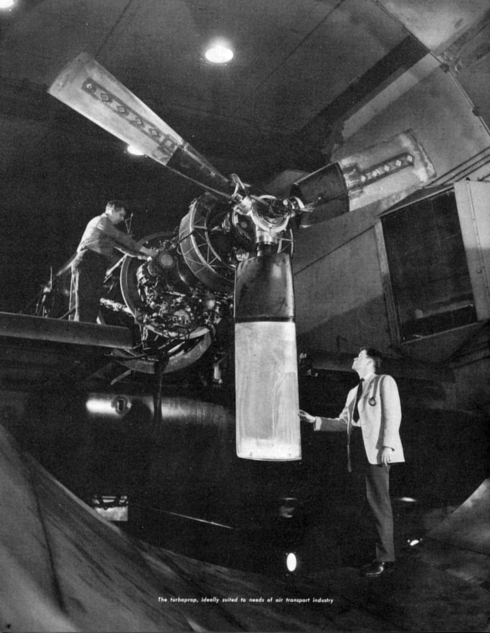
| Fig. 45. Three blade Turbohydromatic in the test cell with camber face of the upper blades instrumented with stress gauges. The impressive chord gives the illusion of small propeller diameter. Picture taken from a Hamilton Standard Family Day brochure, 1953. |
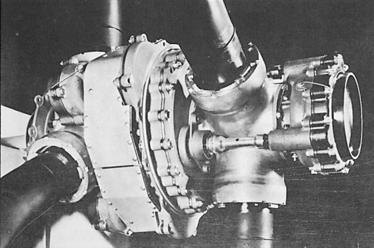
Fig. 46. Turbohydromatic hub undergoing measurement. Note the characteristic "three tube" casting on the barrel-shaped pump body immediately behind the propeller. Picture taken from a Hamilton Standard Family Day brochure, 1953. |
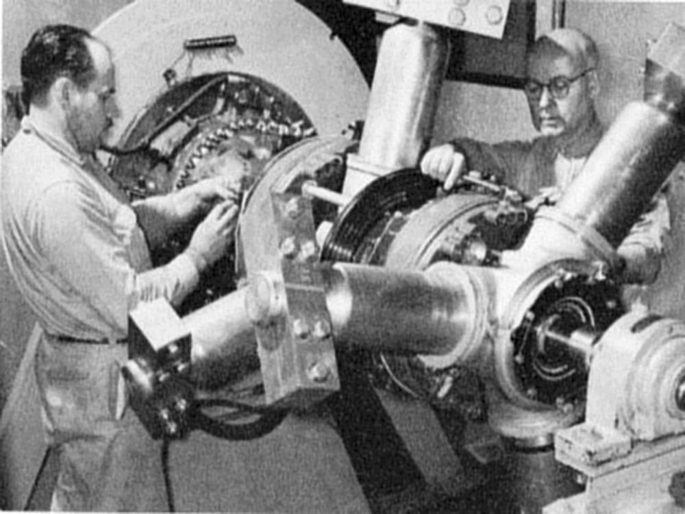
Fig. 47. Six blade Turbohydromatic dual rotation propeller on the test stand. Note the electric slip rings on the rear of the outboard pump body that likely support the new electronic control of the Turbohydromatic. Also of note are the dummy propeller stubs and clamped weights that allow rotational testing without the restrictions of typical propeller diameters. Picture taken from a Hamilton Standard Family Day brochure, 1953. |
Hamilton Standard went on to design and manufacture a number of successful turbopropellers. In particular, the 54H60 turbopropeller that operates on the basic Hydromatic design, and in quartets, have propelled the majority of the 2,500+ Lockheed C-130 and 757 Lockheed P-3 aircraft produced since 1956. The Super-Hydromatic just seemed to fade away.
The Fedden Mission Report to America (Dec 1942) is illuminating as Roy Fedden described the Super-Hydromatic this way: "This propeller has been designed to an ideal specification without regard to simplicity." Perhaps that more than anything sealed the fate of this interesting propulsion system.
Acknowledgements
Many thanks to Paul Christiansen, Kim McCutcheon, Dave Birch, Bill Pearce, Tom Berthold, Graham White, Ted Koch, John Leonard, and Tyson Smith for sharing their time, skills, photographs, and documents.
References
Super-Hydromatic Contractor correspondence, Sarah Clark file 452.14, National Archives and Records Administration, College Park, Maryland.
Douglas XTB2D-1 Skypirate, Naval Fighter Number Thirty Six, by Bob Kowlaski, 1996.
Ryan FR-1 Fireball and XF2R-1 Dark Shark, Naval Fighters Number Twenty Eight, by Steve Ginter, 1995.
Thrusting Forward, A History of the Propeller, by George Rosen, published by Hamilton Standard, 1984.
Consolidated-Vultee XF-81, Air Force Legends Number 214, by Steve Ginter, 2006.
R-4360, Pratt & Whitney’s Major Miracle, by Graham White, Specialty Press, 2006.
R-2800, Pratt & Whitney’s Dependable Masterpiece, by Graham White, SAE, 2001.
Hamilton Standard Employee Day Brochure, 1953, in the collection of the Aircraft Engine Historical Society.
Contraprops: Design and Application, by Stephen Williams, Air Tech Magazine, (month?), 1943.
Handbook of Erection and Maintenance Instructions for the XB-35 42-13603, Airplane, Report HB-20, Northrop Aircraft, Inc., 1947.
Convair's Flying Compromise, by Terry L. Sunday, Wings, Vol. 17 No. 5, October 1987.
Kaiser Fleetwings XTBK-1, by Bob Kowalski, Naval Fighters Number Forty Eight, 1999.
Queen of the Skies, by Claude G. Luisada, Schiffer Publishing Ltd, 2014.
Remembering an Unsung Giant, by Cal Taylor, Firstfleet Publishers, 2005.
Flight Magazine, 4 Mar 1955, 262.