The XB-42 Propeller System:
Independent control of coaxial propellers — How did they do that?
by Tom Fey
Memorial Day 2011; Revised 25 Nov 2023
|
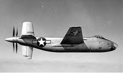
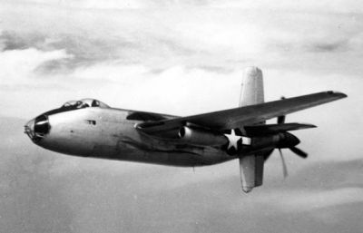
The Douglas XB-42 was a sleek experimental bomber powered by two Allison V-1710 12-cylinder (initially V-1710-103E (E23)) engines that drove contra-rotating pusher propellers in the tail of the aircraft. The design was an attempt to improve upon the speed and maintain the range of a B-17, but in a more efficient package using two engines and a crew of three instead of four engines and a crew of ten. Two prototypes were built and flown, with one additional static test airframe. Eventually, two wing-mounted jet engines were added, resulting in the XB-42A, which survives to this day. Somebody needs to write a book on the XB-42 (two piston engines turning), XB-42A (two turning, two burning) XB-43 (America’s first jet bomber; survives intact) as they are not well known and completely fascinating in design and execution.
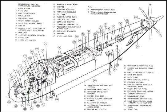 |
| XB-42 Fuselage General Arrangement |
The engines were buried side-by-side behind the cockpit in a stainless steel tub, canted inward towards the tail and inclined 20°, and drove the tail-mounted, modified V-3420-B reduction gearbox via dual, 6-piece, 6-intermediate bearing, 29-foot long drive shafts. Allison truly was the master of complex shafting as this assembly, essentially P-39 components, gave very little trouble during the life of the aircraft. Allison’s expertise in this field continues to this day with the V-22 and F-35.
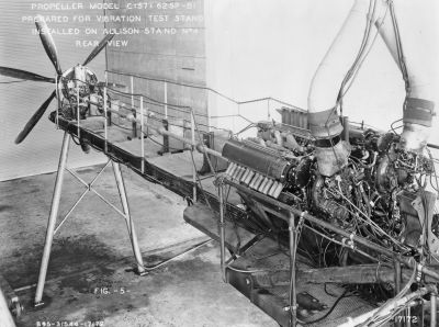 |
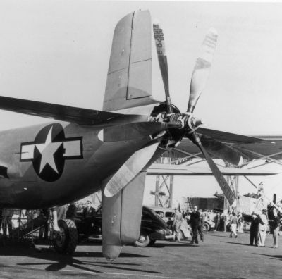
| Curtiss Electric contra prop for XB-42 on Allison test stand #4, driven by Allison V-3420 and extension shafts. Note strain gauges on prop blades and 48 individual straight exhaust stacks. (R-RHT) |
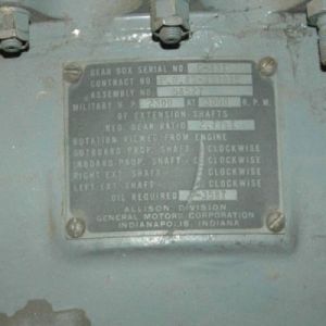
The XB-42 gearbox had a reduction ratio of 2.77 to 1, which was unique to the XB-42. Amazingly, two gearboxes survive; one resides in the NASM XB-42A (now at Wright-Patterson Air Force Museum for restoration) and one in storage at the California Aerospace Museum in Sacramento, California. The gearbox weighed approximately 390 lb and had its own oil cooling system. The weight of the propellers, gearbox, drive shafting, and cruciform tail, as well landing gear that pivoted rearward into the empennage so far behind the wing required the engines to be mounted ahead of the CG to provide proper balance to the aircraft. The gearbox oil cooler ducting is on the port side of the aft fuselage, the intake geometrically camouflaged by aft edge of the star and the exhaust shutter at the aft edge of the bar.
 |
 |
| XB-42 gearbox held by California Aerospace Museum. Unlike the flown, “intact” XB-42A, no terminals were visible in the bore of the prop shaft. |
|
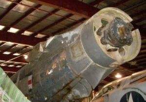
One of the many unique features of the XB-42 was that each engine drove one of the propellers, with the port engine (rotating counterclockwise) driving the inner prop in a clockwise direction when viewed from behind the aircraft, and the starboard engine (clockwise turning) driving the aft prop in a counterclockwise direction. Each power system had independent control of the propeller pitch, including feathering capability for both props, and reverse pitch for the aft prop. Synchronizing capability was also installed. This is an amazing feat of propeller control, and it has taken me 10 years of intermittent research to figure out. Last year’s AEHS trip to the NASM Garber facility where I got to view the partially disassembled XB-42A, produced the final pieces to the puzzle.
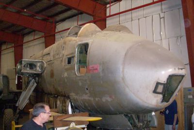 |
| XB-42A at the NASM Garber Facility |
The propellers are each 3-blade Curtiss-Electric units, variably described as C(57) 62SP-B1 (used on Allison test stand) or 836-17C2-18 and 837-17C2-18 (as described in NACA Report L4K09), or 3-C-2 (Dan Whitney). The forward prop had a diameter of 13 feet 2 inches and the aft prop 13 feet, most likely to avoid the impact and vibration of the tip vortices coming off the fore blade tips if they were to be in the same plane as the aft prop. I have been unable to locate technical documents on these propellers, but this is not too surprising since these props were unique to this application and never achieved production status. The blades were of Curtiss two-piece, welded, hollow steel construction, and two types of elongated spinners, one rather long and pointed, the other somewhat shorter and blunted, were used to fair the props to the fuselage.
 |
| See 2005 AEHS Convention presentations (Torque Meter Vol. 2, No.2) |
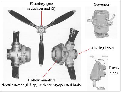
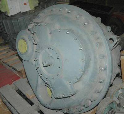
Actuation of the propellers, like all Curtiss constant-speed props of that time, was by electric motors and reduction gearing in the hubs of each prop. Curtiss was uniquely qualified to take on the task of independent control of coaxial, contra-rotating props since it already manufactured a hollow bore, electric propeller (C6315SH) to accommodate the nose cannon of the P-39 Airacobra My best guess is that this basic design, adapted to a 70 spline shaft, was used to actuate the inner propeller. This is supported by the general configuration seen on the XB-42A pictures, including the semi-circular housings found 120° apart around the circumference which house the planetary/bell gear reduction train. I presume a “standard” Curtiss multi-lane brush block assembly would be found attached to the face of the gear box to provide controlling current to the inner prop hub and actuating motor.
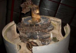
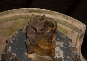
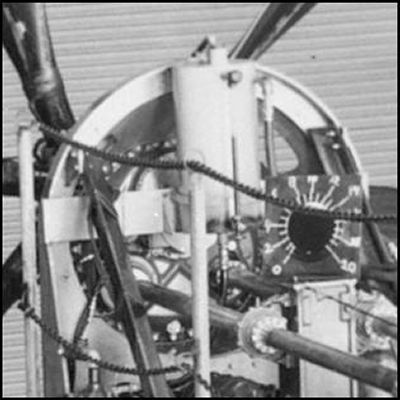
But how was the aft propeller independently controlled? Pictures taken at the Garber facility of the cruciform tail-less XB-42A (aft prop removed and unavailable), and data from the recently acquired maintenance and erection manual show that the hollow bore of the inner prop shaft (supports aft prop) was filled with probably an insulating material which held 2 or more electrical conduits. The picture below right shows what I believe are two electrical posts in the bore of the shaft. My best guess is that a brush block assembly was mounted on the back side (engine-side) of the gearbox that mated with a slip ring assembly that routed conduit through shaft bore. The aft prop, based on pictures and video of a spinner-less XB-42 (www.AeroCinema.com), seems to show a rather standard looking 50-spline Curtiss Electric prop assembly like that found on a P-38, P-51A, or P-40. My guess is that the hub was modified to provide electrical connectors between the prop shaft bore terminals and the prop hub. The hub likely had insulated pins that completed the circuit to the centrally-mounted electric motor and brake assembly. Thus Curtiss was able to use proven designs and technology to achieve independent control of coaxial, contra-rotating propellers.
 |
 |
 |
| Pictures of the XB-42A Propeller Accommodations Taken at the NASM Garber Facility | ||
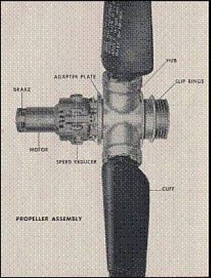 |
(Left) Curtiss Electric propeller as found on P-38 and P-40 aircraft and perhaps the basic design of the aft prop on the XB-42. Insulated pins carry current from slip rings to the motor and brake assembly bolted to front of prop. Brake assembly was spring loaded and “on” when de-energized, thereby locking the blades in the selected pitch until current from the prop governor activated a solenoid to retract the brake and energize the pitch change motor. Amazingly, independent control of coaxial, contra rotating propellers was not unique to Curtiss as Rotol accomplished this trick in the Fairey Gannet by hydraulic means, but that is a story for another time. So how did this independent propeller control work in practice? The answer is quite well. Glen Edwards (as in Edwards Air Force Base) landed the XB-42 in March of 1946 with a feathered inner propeller after the port V-1710 failed catastrophically in flight. The ability to feather one prop was also used by then Lt. Col. Fred Ascani (1917-2010) in December of 1945, while on an engineering test flight out of Bolling Field near Washington, DC. A landing gear malfunction progressed into a fuel starvation problem, the port engine quit, so Ascani feathered the inner prop. Shortly thereafter, the starboard engine lost power likely due to fuel exhaustion, and Ascani had to make use of yet another interesting feature of the XB-42. The pilot had the ability to pyrotechnically jettison the entire gearbox/prop assembly to allow safe bail out from the door in the starboard forward fuselage. Ascani sent the two crew members out before he belatedly severed the props and exited the plane 400 feet above the Maryland countryside. All three aircrew landed safely. Once the 1100+ pounds was lost from 30 feet behind the center of gravity, the plane pitched down violently. |
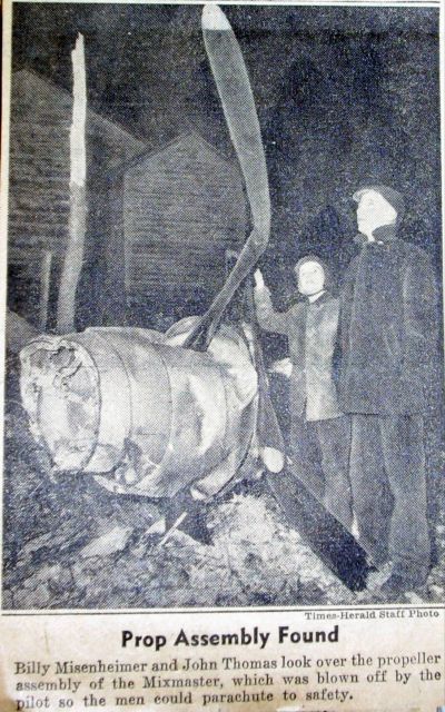 |
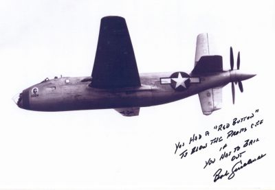
The newspaper clipping at the left (R-RHT) showing the props from the XB-42 was printed Dec. 17, 1945, 42 years to the day since the Wright brothers inaugurated controlled, powered flight. The emergency separation of the props and gearbox was accomplished by lacing carefully-calibrated explosive cord through holes drilled through the 5/32 in thick aluminum bulkhead that secured the reduction gear box in the aft fuselage. “Carefully calibrated” because they wanted to severe just the gearbox and props, not the whole tail of the aircraft. There was a safety-capped red button on the instrument panel that set off the charge. The circuitry was disabled while on the ground and activated pre-takeoff by an interrupter plug located in the left main gear wheel well. I was able to contact General Ascani a few years back and asked him about the contra-rotating props, and he said they were very dependable and never an issue with the aircraft. I was curious to know if the props were destabilizing in yaw, especially being so far aft of the cg. Single seat contra-prop tractor aircraft typically have giant vertical stabilizers such as F.47 Spitfires, Westland Wyvern, RB-51 air racer, Douglas Skypirate and Skyshark. The final iteration of the XB-42 had a significantly taller dorsal vertical stab, and I thought maybe this was designed to address this potential instability. Gen. Ascani said the XB-42, regardless of which tail, did not suffer from lateral instability. Pretty cool getting the word from a test pilot who did the flying. I’ve been in contact with the Air Force Museum and hope to get a chance to more closely examine and photograph the XB-42A’s propeller assemblies and gearbox whenever it undergoes restoration. I love a good mystery, and hopefully I’m not too far off with my theory of design and operation. Curtiss manufactured constant speed, contra-rotating props with slaved actuation of the second blade set for both piston-powered (XP-56, XP-62, XBTC-2, XF-14C) and turboprop aircraft (XFY-1, XFV-1, X-18). The little information I have been able to find shows them to be fascinating in both design and execution, and once I get a bit more info, I’ll tell this story at a later date. |
 |
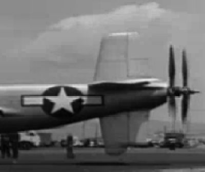 |
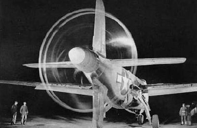
| The Douglas XB-42A in flight. Engine air intake is flush duct below canopy. Black engine exhaust stain on fuselage directly above leading edge of the wing. Oil breather blow-by is long dark swoop under wing. Westinghouse 19B-2 turbo jets on wing. Note the taller dorsal vertical stabilizer. (R-RHT) | Screenshot from film that shows the XB-42 propeller assemblies without spinner. Note the relatively shorter dorsal vertical stabilizer. (www.AeroCinema.com) |
 |
 |
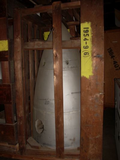
| Elegant, pointy spinner crated and ready for shipment to the Air Force Museum in Dayton, OH, July 2010 | Close up of the backside of the XB-42 props on the Allison test stand. I’m guessing the white circular assembly with a squared left edge (behind the tall rectangular tank and horizontal strap) is the housing for the brush block assembly that controls the outermost (aft) propeller. (R-RHT) |
 |
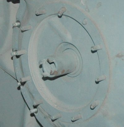 |
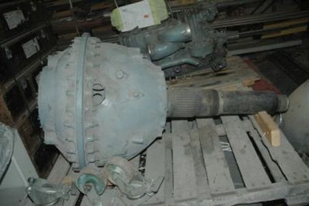
| Backside of the Sacramento XB-42 gearbox. I’m guessing a brush block assembly was somehow attached to the 4-prong drive cog and that electrical conduit ran through the center prop shaft bore. Unlike the intact XB-42A, no terminals were in place in this gearbox. Yellow caps cover the drive shaft inputs. | |
 |
|
| General Robert Cardenas had a long and distinguished test flight career, including test flying the XB-42 / XB-42A and piloting the XB-42A on its final flight to (Aug. 8, 1948) to Orchard Place Airport (ORD; now O’Hare Field, Chicago, IL) to the custody of the National Air Museum Storage Activity. | |
XB-42 Data Sources
Sources:
Original autograph of XB-42 test pilot Gen. Robert Cardenas from the collection of Tom Fey obtained by personal correspondence, 2008
Email correspondence with Maj. Gen. Fred Ascani, 2008-2010
XB-42 Maintenance and Erection Manual
XB-42 Pilots Manual
Rolls-Royce Heritage Trust - Allison Branch, Indianapolis, IN
Pictures taken by author at the NASM Paul Garber Restoration Facility, Silver Spring, MD, during AEHS convention visit in August 2010 and the California Aerospace Museum during the AEHS convention visit in July 2008.
Internet sources as noted
References:
Vee’s for Victory, Dan Whitney, Schiffer Military Publishing, 1998
Elegant Failure, America’s Forgotten Wings, Air Classics Review #1, 1994
The First, The Last, and The Only XB-42/42A/43, Walt Boyne, Airpower Magazine, Vol. 9, #6, 1979
The Douglas XB-42 Bomber of 1944, Robert F. Dorr, Aviation News, April 1985
Design and Development of the XB-42, Carlos Wood, American Aviation Historical Society Journal, Vol. 47, #3, 2002
NACA XB-42 model performance reports
A5J12 Aerodynamic characteristics of a 1/8 scale (XB-42)…
A4K04 Estimated flying qualities of (XB-42) from 1/8 scale…
L4K09 Investigation of tail-prop interference (XB-42) …
The End
 |
 |
| Curtiss Electric Coaxial Propeller Set on the XB-42. (From the Gerald Balzer Collection, Courtesy of the Greater St. Louis Air & Space Museum) |
A copy of this article with large images is available in the AEHS Member's Section
Send mail to
![]() with questions or comments about this web site.
with questions or comments about this web site.
![]()