
Curtiss
Turboelectric
Propeller
The Last Flying Curtiss Turboelectric Propeller
by Tom Fey
Published 20 Aug 2019; Revised 25 Aug 2019
Curtiss Turboelectric Propeller |
The Curtiss / Curtiss-Wright Corporation manufactured airplane propellers since the early days of aviation and well into the 1950s. The culmination of their engineering prowess were the 19 foot diameter, 3 blade pusher props on the B-36, the 16 foot contra-rotating propellers that dead-lifted the Lockheed XFY-1 vertically into history, and the subject of this article, the 18 foot diameter 3 blade Turboelectric propeller used predominantly on the Douglas C-133 Loadmaster. The C-133A/B (50 built), YC-121F (2 built), the R7V-2 (2 built), YC-97J (2 built), and YC-124B (1 built) all used the Pratt & Whitney T34 engine. Only the T406 engines in the Osprey, the TP400 engines in the A400M, and Kuznetsov NK-12 engines in the Tu-95 are more powerful than this relic from the 1950s. The majority of T34-powered aircraft used the Curtiss Turboelectric propeller; however the YC-121F used the Hamilton-Standard A-3470-5 |
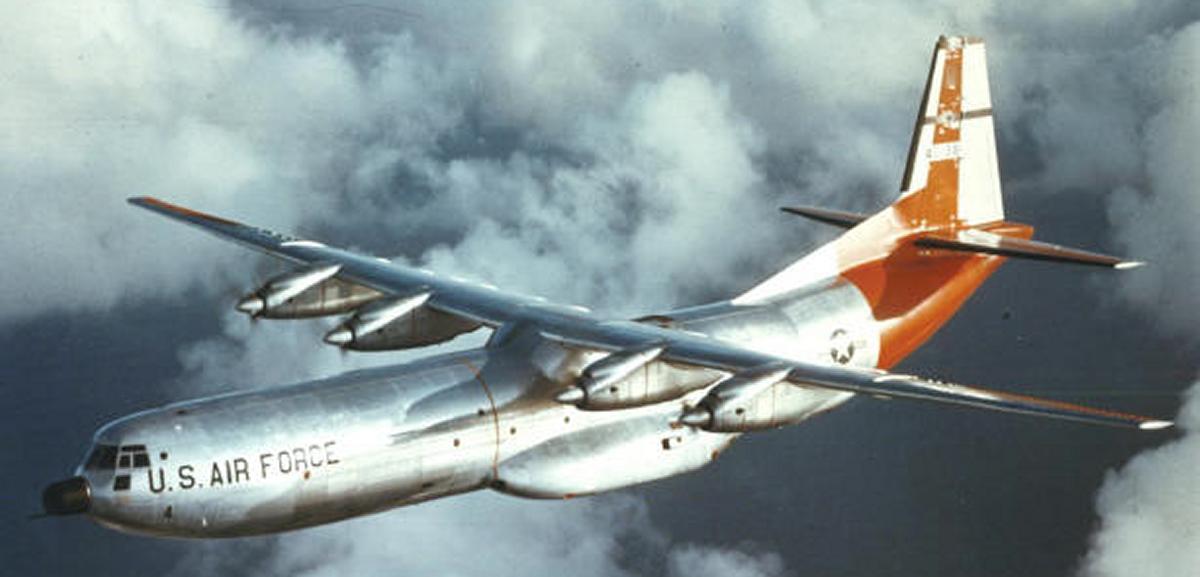
The Douglas C-133A/B heavy transport is covered in remarkable detail in the 420 page book Remembering and Unsung Giant by Cal Taylor. The book chronicles the testing, the adoption into service in 1956 carrying Titan ICBM missile assemblies, ship propellers and drive shafts, Apollo space capsules, five UH-1 Huey helicopters per load to Vietnam, and other outsize cargo for the US military. The C-133 fleet was retired from military service 15 years later. The book is very highly recommended. I never thought a transport aircraft could be so fascinating (Fig01).
This article will focus on the Curtiss CT735S (Curtiss –; Turboprop – SAE #70 spline prop shaft – 3 blade – # 5 blade shank size – Steel) series of turboelectric propellers used on the C-133. Amazingly, the final flight of a Curtiss Turboelectric propeller was in 2008, but more on that later. Since propeller performance and design are intricately linked to the power plant and the performance envelope of the aircraft, some background on the T34 is in order.
 |
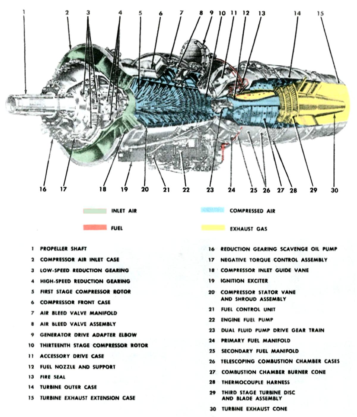 |
| Fig01. C-133A, 62014 over San Francisco, April 1959 (Cal Taylor/USAF/Douglas) | Fig02. Pratt & Whitney T34 Turboshaft Engine. The engine was 33.75 inches in diameter, 157.4 inches (13 feet) long, and weighed approximately 2,590 lb dry. |
The T34 would make fascinating article in and of itself (Fig02). It was a 157.4 inch long, 2,564 lb, single shaft engine with a 13-stage axial flow compressor that achieved a 6 to 1 compression ratio while flowing 100 lb of air per second. The compressor was mated to a 3-stage turbine with shrouded blades, which in turn drove a compound epicyclic gearbox with a reduction ration of 11 to 1. The engine started out at 5,700 ESHP (equivalent shaft horsepower, which is the sum of shaft horsepower plus residual exhaust thrust mathematically converted to power), and eventually 6,500 to 7,500 (wet) ESHP. The engine never quite achieved the power that was expected in the C-133 design, and this produced an avalanche of changes to the airframe that would come back to complicate the working life of the aircraft. The engine, once early reduction gear problems due to aeration of the lubricating oil were partially corrected, was well behaved and quite reliable in service.
While the engineering required to efficiently convert 3200+ hp from a piston R-4360 into thrust are considerable, it is significantly more complex to control the 6500+ hp of the T34. The power characteristics of the turboshaft engine are very different from reciprocating engines. For efficiency and to enable rapid changes in power without delays due to “spooling up” of the power turbine, turboshaft engines are run at constant speed and within a very narrow rpm window. Fabulously complex fuel controls (Fig03) are integrated with rapid-acting propeller pitch controls to maintain turbine speed within a 3% to 6% range, regardless of power. This was still the age of aneroids, bellcranks, cams, levers, diaphragms, balance tubes, pilot valves, gear trains, lead screws, and analog wizardry.
In flight, the T34 turbine speeds were maintained between 10,670 rpm (97.7%) and 11,000 rpm (100%), resulting in prop speeds of 970 to 1,000 rpm. One thousand one hundred two rpm was considered propeller overspeed. Fuel flow for each engine was between 700 and 4,250 lb/hr (approximately 108 to 654 gallons/hour), and the aircraft held an astonishing 118,534 lb of fuel (18,236 gallons). Oil capacity was 15 gallons per engine, however oil consumption was a paltry 0.5 lb (approximately 9 fluid ounces) per hour per engine.
The narrow rpm range in flight is required because if the turbine speed sags too low, engine power and temperatures can fall outside the desired limits and cause potentially unrecoverable power loss, damage to the engine, and jeopardize flight safety. Allowing the RPM to exceed the upper limits can result in catastrophic failure (thrown blades) of the propeller or power turbine assemblies, both of which operate very near the limits of the metallurgic science of their times.
Flight conditions and the constant-speed nature of the turboshaft engine demands precise, rapid control of the propeller and fuel into the engine. If descending flight caused the prop to start to drive the turbine, a redundant negative torque control (NTC) system would kick in at 102.3% rpm to increase the pitch of the blades, reducing the windmilling effect, and get the rpms back to 100%. Remember, when the prop increases one rpm, the turbine will increase 11 rpm, a ratio that can rapidly put the turbine blades at risk of failure. The permissible exhaust gas temperature range was 400°C (752°F) to 505°C (941°F) for continuous power, not to exceed 760°C (1,400°F).
The NTC signal is generated by the reduction ring gear at the front of the engine. When the engine is driving the propeller, the angled teeth on the ring gear move the gear aft, and this movement is detected and quantified by the torquemeter to measure power output. When the propeller tries to drive the engine, the ring gear slides forward, mechanically driving a plunger rod that activates a switch to energize the Increase Pitch clutch. Once the engine returns to driving the propeller, the plunger rod retracts, and propeller control goes back to the normal governing circuit (Fig 3a).
For the T34 in the C-133, “low idle” on the ground was 6,000 rpm (55.5%) to decrease noise, and “high idle” was 10,000 rpm (90.9%) to allow taxiing. The engines actually ran hotter internally at Low Ground Idle than at High Ground Idle, so 2 minutes of the latter was required before shutting down to prevent turbine blade rubbing. Of interest is the diagram from the C-133 pilot’s manual showing the prop/jet blast from the C-133 at Low Ground Idle and full power, as well as the Danger Zones for “turbine disintegration and propellers”. Even at Low Ground Idle, a wind of 84 knots at 250° F occurs just aft of the wing. And that doesn’t count the port side Ground Turbine Unit (GTU) exhaust of 175 knots at 350°F! Everything about this plane was big (Fig04).
 |
 |
 |
| Fig03. Fuel control for the T34 turboshaft engine used in the Douglas C-133. | Fig03a. Negative Torque Control (NTC) actuator on the T34 nose case. When the propeller starts to drive the engine, the ring gear translates forward on the spline, driving the plunger rod forward, which energizes the Increase Pitch clutch. | Fig04. Danger Area diagram specifying downstream temperature, wind speed, and component failure threats from the C-133 aircraft during ground operations. |
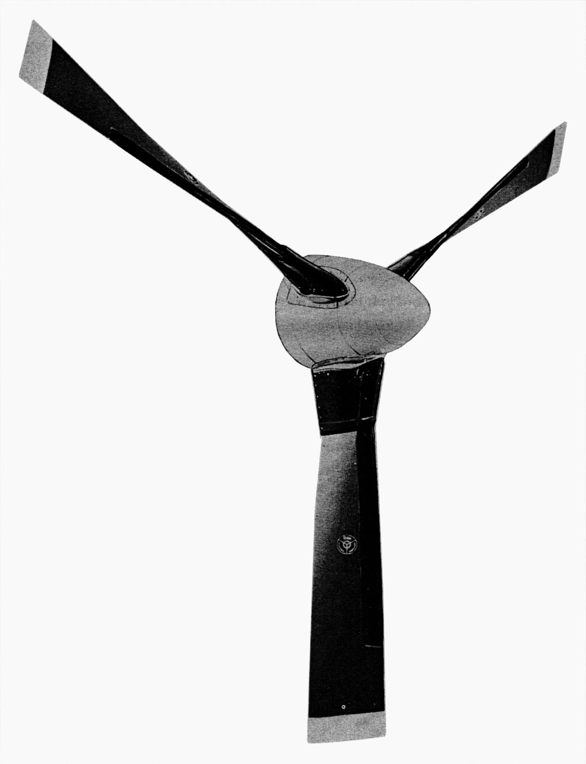
The 3 blade CT735S-B319 Turboelectric propellers were 18 feet in diameter and weighed 1,325 lb per unit (Fig05). The 1060-20C5-12 blades were formed from extruded steel by a proprietary Curtiss process, resulting in a hollow blade with dual span-wise spars and a tip chord of 16.75 inches and a tip thickness of 0.687 inches. Aerodynamic blade root cuffs “resistant to a sledgehammer” were bolted to the roots and the blade angles were indexed to +/- 0.5° of each other. The three blades per propeller were “aerodynamically balanced” by micro-indexing to equalize thrust due to small manufacturing differences in the shaping of individual blades.
The propeller control and pitch changing system consisted of two main assembles; the power section that housed the gearing for changing pitch, and the rear housing, which contained the pitch change clutches, oil filter, and oil pump. The propeller control system was electrical, incorporating reverse pitch, blade angle follow up with system with fuel control for ground operation, negative torque control, manual feathering, synchrophasing, and electrical deicing of the spinner, the leading edges of the blade cuff, and a portion of the leading edge of the blade. The blade angle control system was powered by 28 volt DC current, while deicing of the blades and spinner assembly was powered by a timer assembly and 115/200 volt, 400 cycle alternating current. Electrical power for deicing was transferred to the prop via a 4 lane brush block assembly (Fig06).
 |
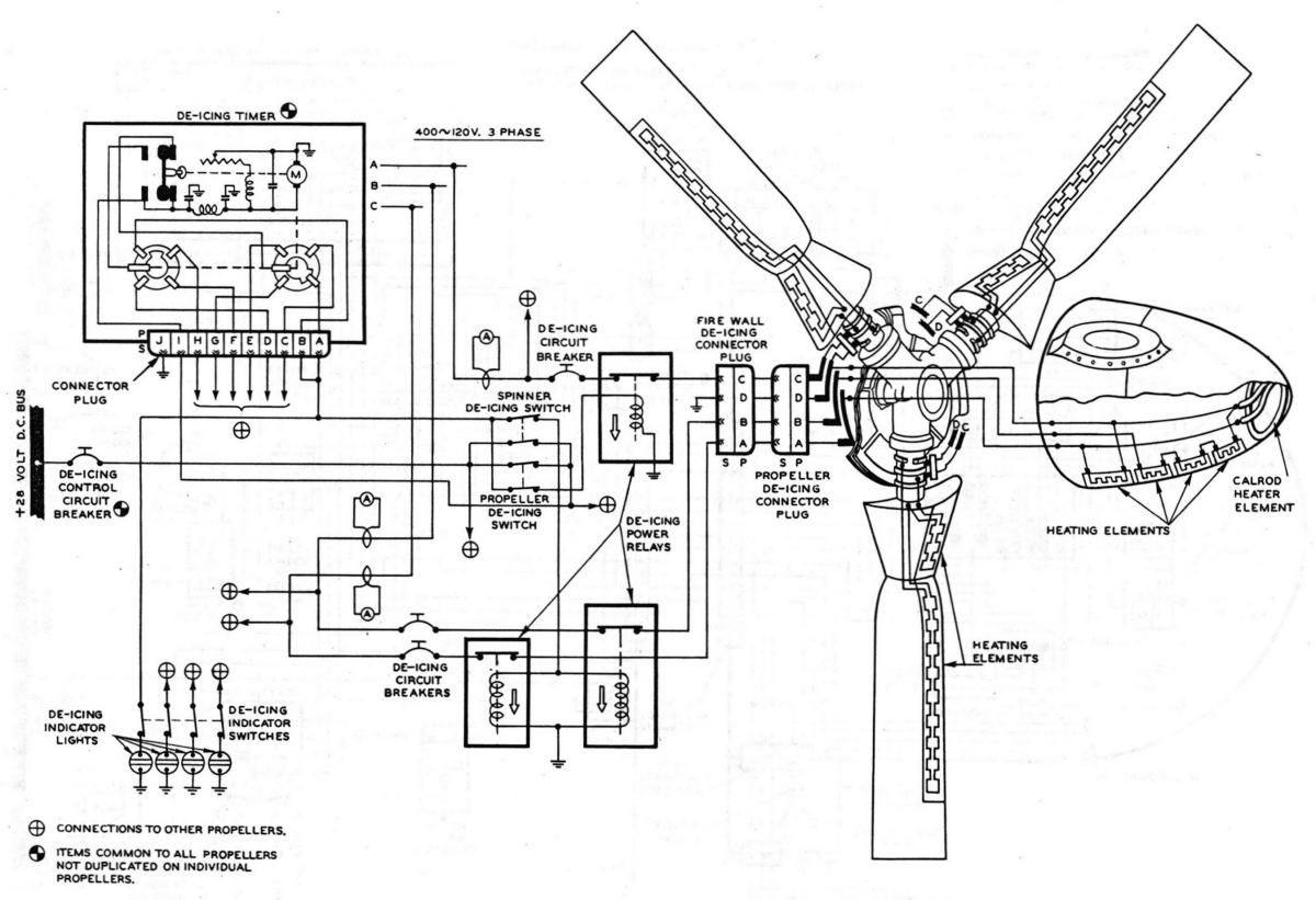 |
| Fig05. Curtiss Electric CT735S-B102 Turboelectric Propeller. | Fig06. Schematic for electrical deicing of the Curtiss CT735S Turboelectric Propeller. |
Curtiss had long experience with electrically-actuated pitch change mechanisms that amplified torque from the modestly-sized electric motors via gear trains with very large reduction gear ratios. Because of these large reduction ratios, pitch change rate was generally slower than hydraulically-actuated propellers.
Before discussing the Turboelectric propeller further, it was my great fortune to make contact with Robert “Bob” Stegner who spent 13.5 years in the USAF and is an expert on the Curtiss Turboelectric system. Bob kindly shared numerous documents on the C-133 propulsion system, as well as his experiences with the finicky engineering masterpiece. Bob commented that it “took the average smarty pants” about 3 years to reach total proficiency on the complex T34/Curtiss Turboelectric propulsion system. After reviewing his remarkable documents, reading about the C-133 and the CT7535S-B102 propeller, I think 3 years to infinity might be a more appropriate answer. As such, I will not delve into the myriad detailed complexities of this propulsion system. I will try instead to explain the basics and hopefully leave a feeling for what Bob’s troubleshooting career must have been like.
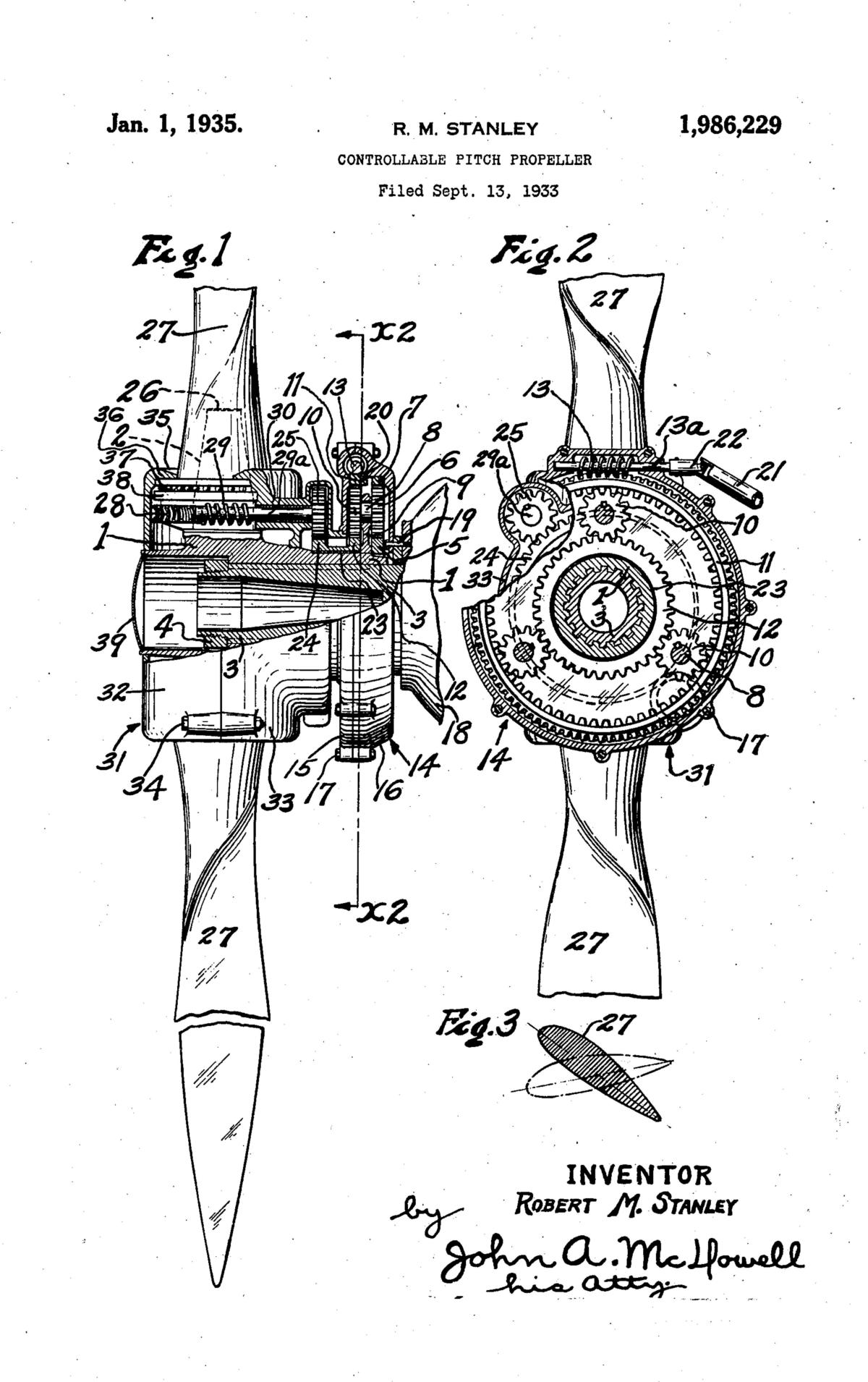
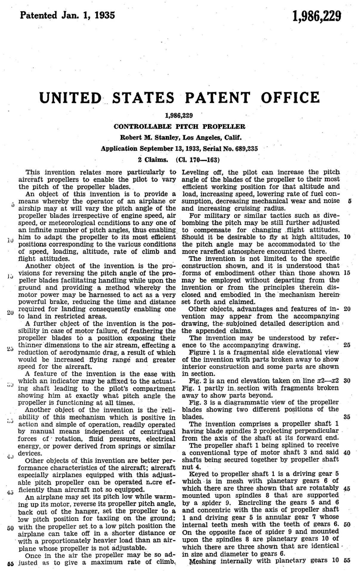
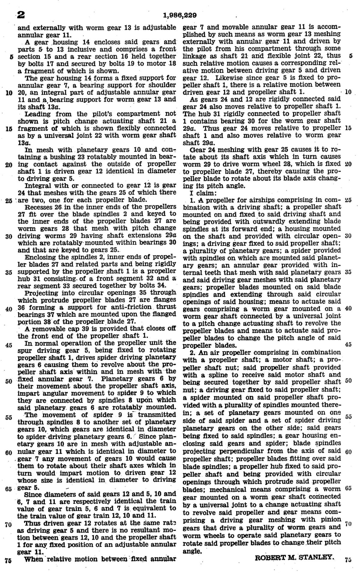
The design of the gear train used in the Curtiss Turboelectric propeller goes back perhaps to a patent filed in 1933 by Robert M. Stanley and granted in September of 1935 (Fig07, Fig08, Fig09).The patent describes the use of a worm drive to “re-index” dual concentric planetary gear trains with mismatches in gear diameters (tooth number) of the pinions that traverse in the gears sets in two places. The result is that one set of planetary gears wants accelerate in speed (advance index compared to prop shaft speed), while the following set of planetary gears wants to decelerate (retard index) compared to the prop shaft speed. When the pitch change worm gear is held stationary, the pinions can be thought to “run place” with no net relative movement between the prop shaft drive gear 5 and pitch change gear 24, thus no pitch change. However, when a pitch change signal is transmitted to the annular gear 11, gear 11 changes its index. This change is transferred to pinion gear 6/10, which re-indexes the second annular gear (23/24). The annular gear 23/24 is connected to the base of the blades via a pinion gear-drive shaft-worm gear that turns the blade on its own axis. Once the pitch change input gear becomes stationary, the gears sets go back to “running in place”.
The German Vereinigte Deutsche Metallwerke (VDM) propeller of WWII used the exact same mechanism for pitch change on their propeller; however there is no record of licensing between VDM and Robert Stanley. Perhaps it was coincidental invention by Stanley and Dr. Hans Ebert of VDM. I suggest the reader grasp the basics of the conceptual schematic of the VDM propeller (Fig10), and once understood the actuation principles are the same for the Curtiss Turboelectric with one exception: the source of the primary motive power source for pitch change.</sidebar>
 |
 |
 |
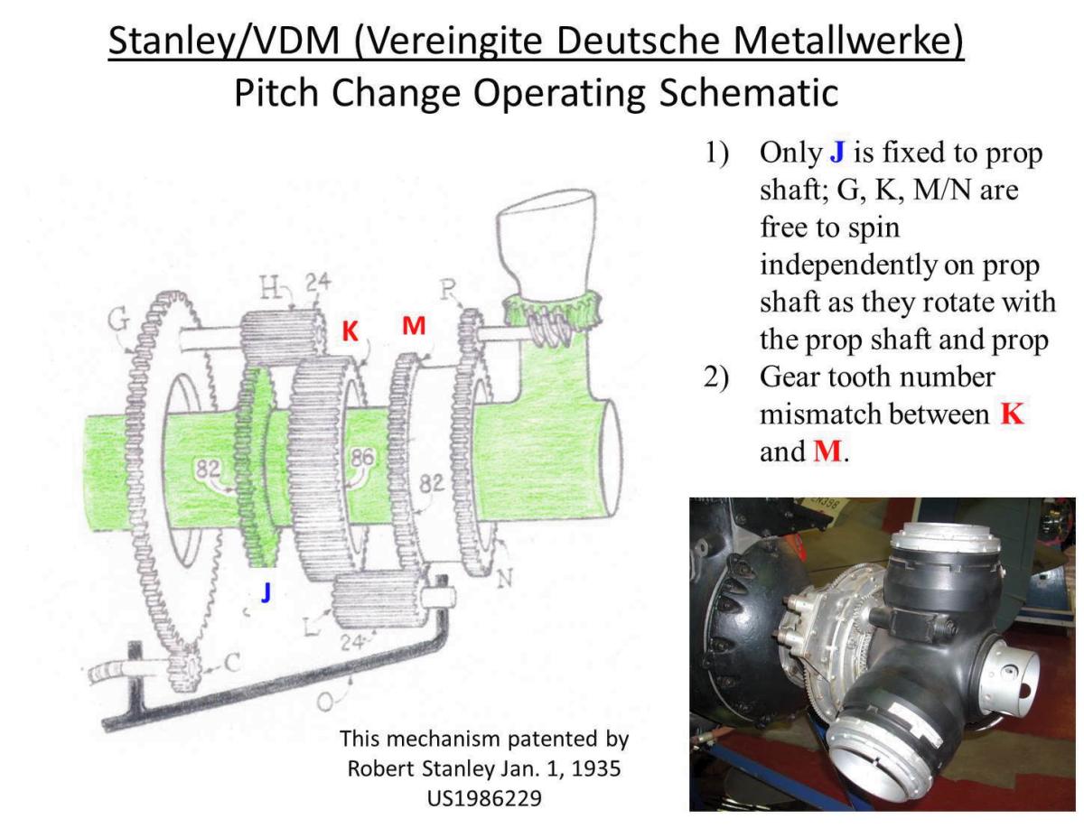 |
| Fig07, 08, 09. Robert M. Stanley‘s novel propeller pitch change mechanism, US patent 1,986,229 granted on 1 January 1935. | Fig10. Operational schematic of the VDM electric propeller as used on 90% of the German aircraft in WWII. | ||
The power required to adjust the pitch of an almost 9 foot long Turboelectric propeller blade absorbing 2,200 horsepower is staggering. To execute such a feat, Curtiss chose to tap the motive power for pitch change directly from the propeller shaft. The control and actuation system needed to be able to adjust propeller pitch for positive pitch in flight, neutral thrust for engine starting, reverse thrust (-9° pitch) for reducing the landing roll, and feathering for inflight shut down of an engine. Because of the massive power source available for pitch change, Curtiss could do away with the torque-multiplying reduction gear sets of the WWII props, resulting in a much faster pitch change rate required for turbine applications. The CT735S propeller had a flight pitch change rate of 20° per second while the feathering system could produce 5° of pitch change per second.
The schematic diagram for the Curtiss Turboelectric propeller is complicated (Fig11). In Figure 12, the assemblies in green are “hard” connected to the propeller shaft and thus spin with the propeller shaft. The components shown in red are assemblies that are not “hard” connected to the prop shaft and thus may orbit, rotate, or be indexed with respect to each other and/or the prop shaft as pitch signals are executed. An Increase Pitch signal is shown in Figure 12.
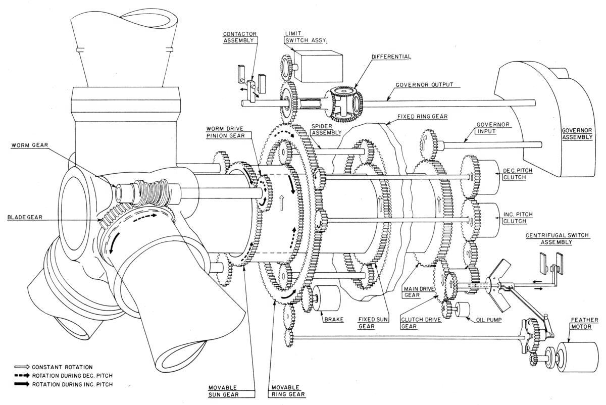 |
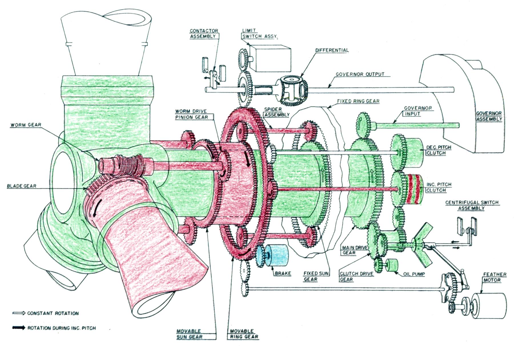 |
| Fig11. Operational schematic of the Curtiss CT735S Turboelectric propeller. Note the shaping of the worm gear at the base of the propeller blade. This spool-shaped design maximized tooth contact area and minimized the tooth loading for this highly stressed component. (T.O. 3E3-2-11). | Fig12. Operational schematic of the Turboelectric propeller using green to denote assemblies “hard” linked to the propeller shaft. Assemblies shown in red either rotate or orbit freely around the propeller shaft, or are under active control by the pitch change mechanism. The Increase Pitch clutch is engaged. |
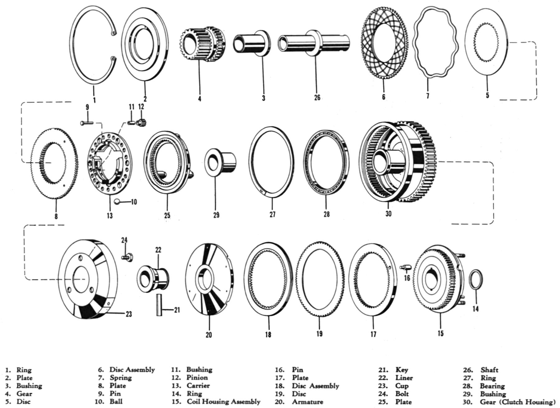
Since the input power from the rotating engine/propeller shaft for pitch change was always “on” when the engine was turning, there were electronically activated friction clutches geared to the movable ring gear. One clutch for positive pitch change, another geared to spin in the opposite direction for negative pitch change. These clutches were about six inches in diameter, about four inches thick, with multiple interleaved discs, and used a coil to activate a drag clutch ball ramp force multiplier to compress the discs together (Fig13). These clutches ran in oil. The Increase Pitch clutch had to overcome the powerful centrifugal twisting moment and aerodynamic forces that try to force the blade to flat pitch, while the Decrease Pitch clutch had a lesser workload.
When propeller pitch/engine speed was “onspeed”, both pitch change clutches were disengaged and a brake circuit, colored blue on Fig12 (8 disc pairs; dry type) was activated, holding the Movable Ring Gear, and through the gear train, the Movable Sun Gear in place and allowing the pinions to orbit freely. Upon appropriate electrical command, say for increased pitch, the brake would be deactivated, the Increase Pitch Clutch (only) would be activated, and motive power would be transferred from the propeller shaft though the clutch, to the Moveable Ring Gear to “re-index” the system and increase the pitch of the propeller blade. To decrease pitch, the brake would be deactivated, the Decrease Pitch clutch would be activated, and the Increase Pitch clutch deactivated (open). There was also a “dead man” solenoid-operated, mechanical ratchet pitch-locking system in the forward section of the propeller spinner that would lock the blades in place in response to certain system failures. Interestingly, blade pitch could still be increased, but not decreased, when the pitch lock was activated.
The easiest way to get a grip on the Curtiss gear system is to imagine the propeller is at rest and follow the Feathering Motor gear train. Once that is understood, just replace the Feathering Motor drive with the Increase Pitch clutch that harnesses power from the propeller shaft to rotate the moveable ring gear.
Gearing taken off the propeller shaft drove the driving side of the pitch change clutches, the propeller governor input, an oil pump, and a centrifugally driven switch that toggled the propeller into Beta Mode and engaging the feathering motor for control of propeller pitch when prop speed was below 25% of rated speed such as during start up and taxiing. Once prop rpm was greater than 25% of rated speed, the centrifugal switch disengaged Beta Mode and activated the propeller governor control of the propeller. Pitch limit switches were geared to the Moveable Ring Gear.
The Governor Assembly drove the Contactor Assembly that was responsible for opening and closing the circuits to drive the appropriate pitch change clutches, and this operation was modulated by a Differential assembly geared to the Moveable Ring Gear.
So if the propeller pitch change system used power from the rotating propeller shaft, how could a stationary propeller be unfeathered? That is where the feather motor comes into play. When activated by the flyweights that detect low engine speed, the electric feather motor gets clutched in to drive a gear train meshed to the Movable Ring Gear, thus turning the blades.
The propulsion control system consisted of “a constant speed governor, assembly mounted in the power unit rear housing, a synchronizer assembly mounted in the aircraft, two Beta units (ground operation) coordinator assemblies mounted in the aircraft, a propeller coordinator mounted on the fuel control unit of each turbine, a negative torque switch assembly mounted on each turbine nose section, and the necessary control circuit breakers and switches.”
Propeller control is effected by two separate control systems that are actuated by the pilot’s power lever. The first system is the flight regime that operates through the propeller synchronizer/governor. The second system is Beta Mode for ground operations when the power lever is below flight idle gate and a coordinated blade angle control system is energized. The “simplified” diagram and explanation are shown in Figure 14.
 |
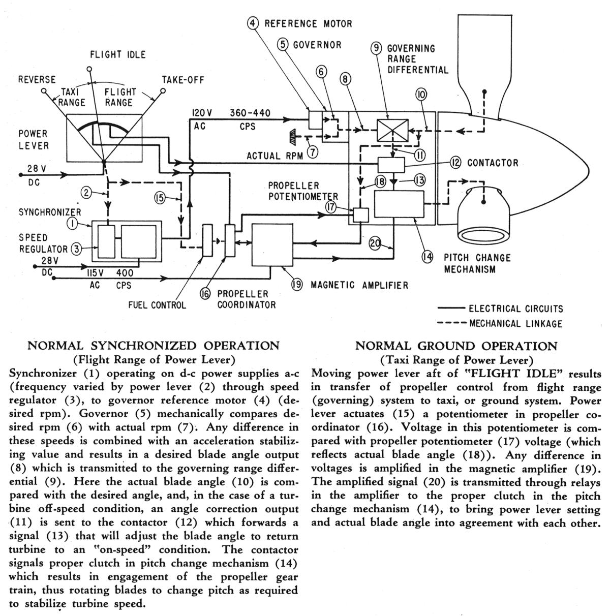 |
| Fig13. Exploded diagram of the Decrease Pitch clutch. When the coil is electrically energized, a ball ramp torque multiplier (xx) pressed the discs together, rotating the pinion and indexing the movable Ring Gear to a decrease pitch via the rotating gear train. | Fig14. Simplified control schematic of the propeller and control assemblies. “Simplified” should not be confused with “simple”. |
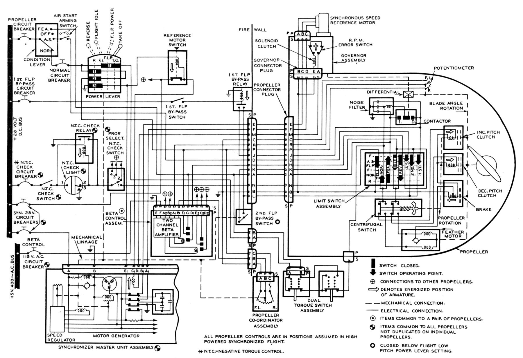
The propeller governor system is complicated beyond what I can fully understand much less explain (Fig15, Fig16). Suffice it to say that it is exquisitely sensitive to rpm changes and is able to “lead’ changes in pitch setting via sensors, potentiometers, and balance circuits to keep the engine/propeller within the specified rpm range (Fig17).
Bob passed along several interesting bits of information on the Turboelectric propeller. Some of the early troubles were caused by disintegrating Increase Pitch clutches. The torque was so great that a 1/4 inch thick snap ring (# 14 in Fig13) that held the clutch pack together couldn’t withstand the load, disintegrating the clutch and causing an emergency pitch lock response, typically followed by an emergency landing. A 3/8 inch snap ring remedied that issue.
 |
 |
 |
| Fig15. Mechanical schematic of the propeller governor assembly. The traditional flyweights and speeder spring are present, but are highly modulated by assemblies that increase the precision and response rate of pitch change. | Fig16. The electrical schematic for propeller control. The numerous wires and cannon plugs were adversely affected by the vibration caused by such large propellers, and in the case of the C-133, with fatal consequences. | Fig17. Photograph of the case-less Governor. This precision electromechanical clockwork, along with the fuel control, are responsible for safely regulating 6,000+ horsepower. |
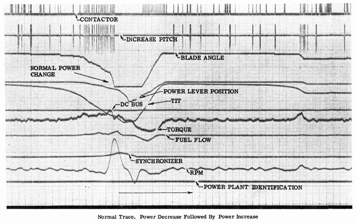
Late in the career of the C-133, Honeywell and Curtiss Wright developed an onboard analyzer tailored for troubleshooting the T34/Turboelectric propeller propulsion system. The analyzer monitored fourteen parameters on each engine making traces similar to heart rhythm EKGs, on light-sensitive paper (Fig18, Fig19). The analyzer would monitor one engine for one minute, rest for six minutes while crew read the squiggles, then move on to analyze engine #2, etc.
One anomaly detected by the analyzer was that the Increase Pitch clutch circuitry was overly sensitive such that the energize/de-energize cycle was so frequent and of such short duration that very little pitch change was occurring. This caused excessive wear on the clutch, and was eventually remedied with the use of desensitizing circuitry.
 |
 |
| Fig18. A Power Plant Analyzer System trace showing normal function during a power reduction and subsequent power increase. Time is along the bottom axis and the Analyzer could be adjusted to expand or compress the tracings. The paper itself was the only record of the Analyzer output. | Fig19. A Power Plant Analyzer System trace showing “pending” failure of the propeller. Even though the contactor was quite active signaling a need to change propeller pitch, little pitch change was achieved. It must have been terrifying to see such a trace over the northern wilderness or Pacific Ocean, far from home. |
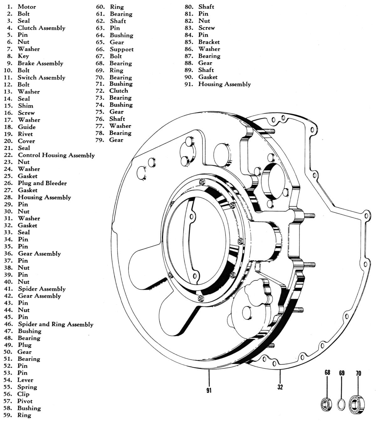
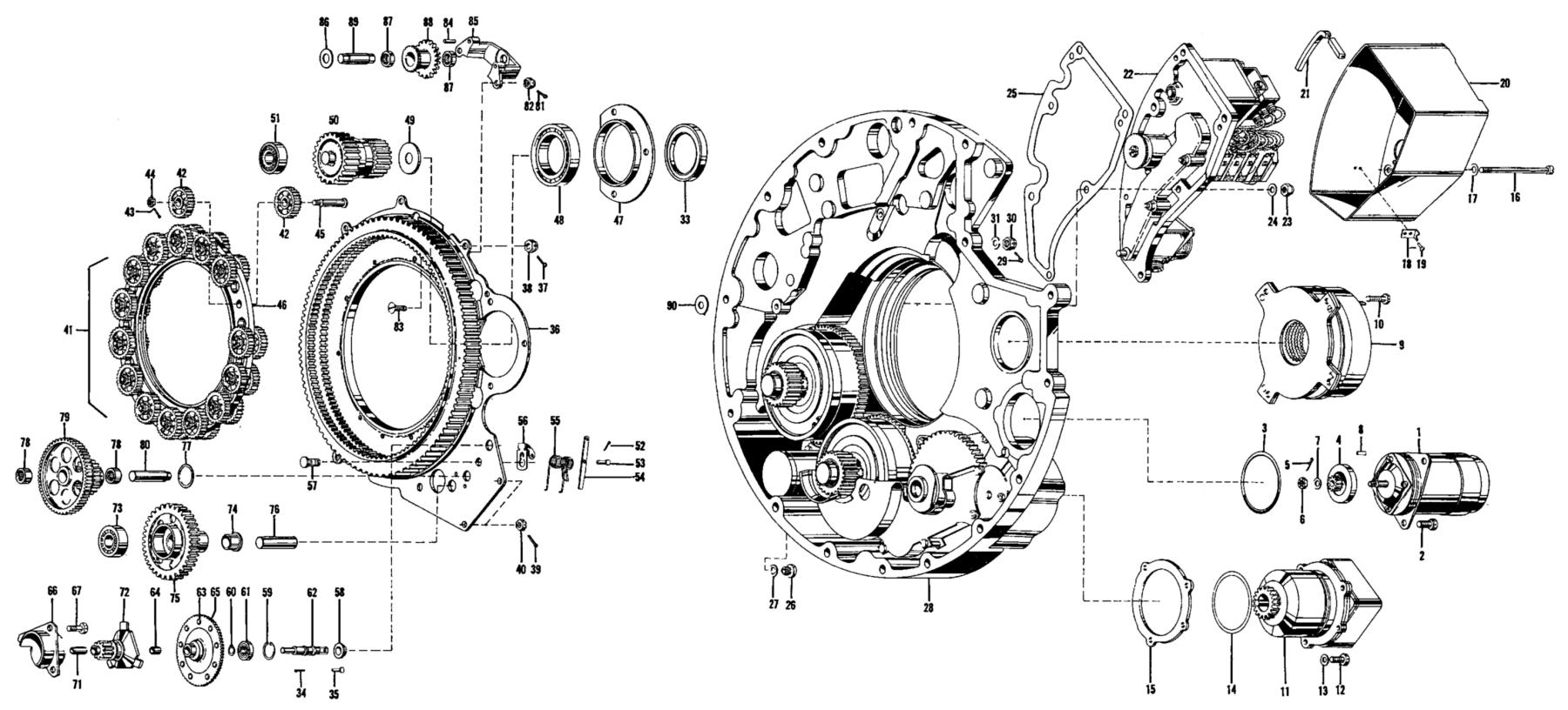
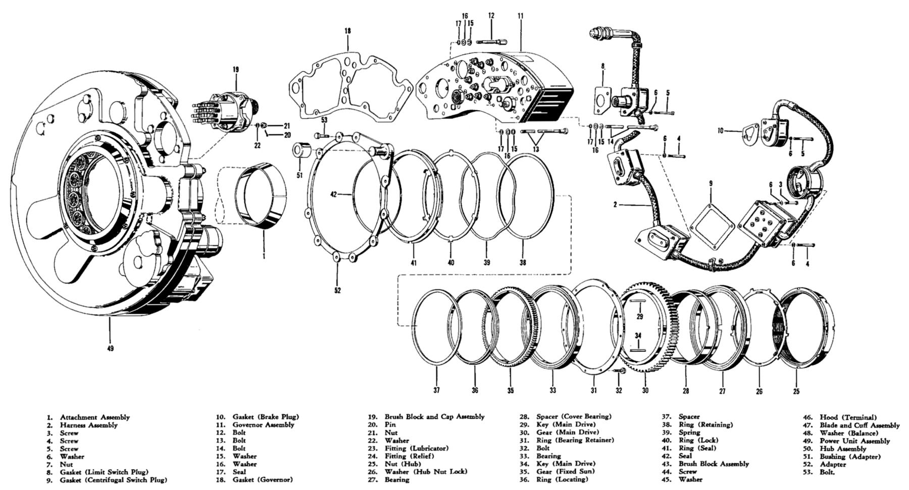
Exploded diagrams of the propeller hub, front cover, power unit, propeller assembly, and rear housing section are included to once again show the complex nature of these assemblies and the machining skill required to execute the design (Fig20, Fig21, Fig22, Fig23, Fig24).
 |
 |
 |
 |
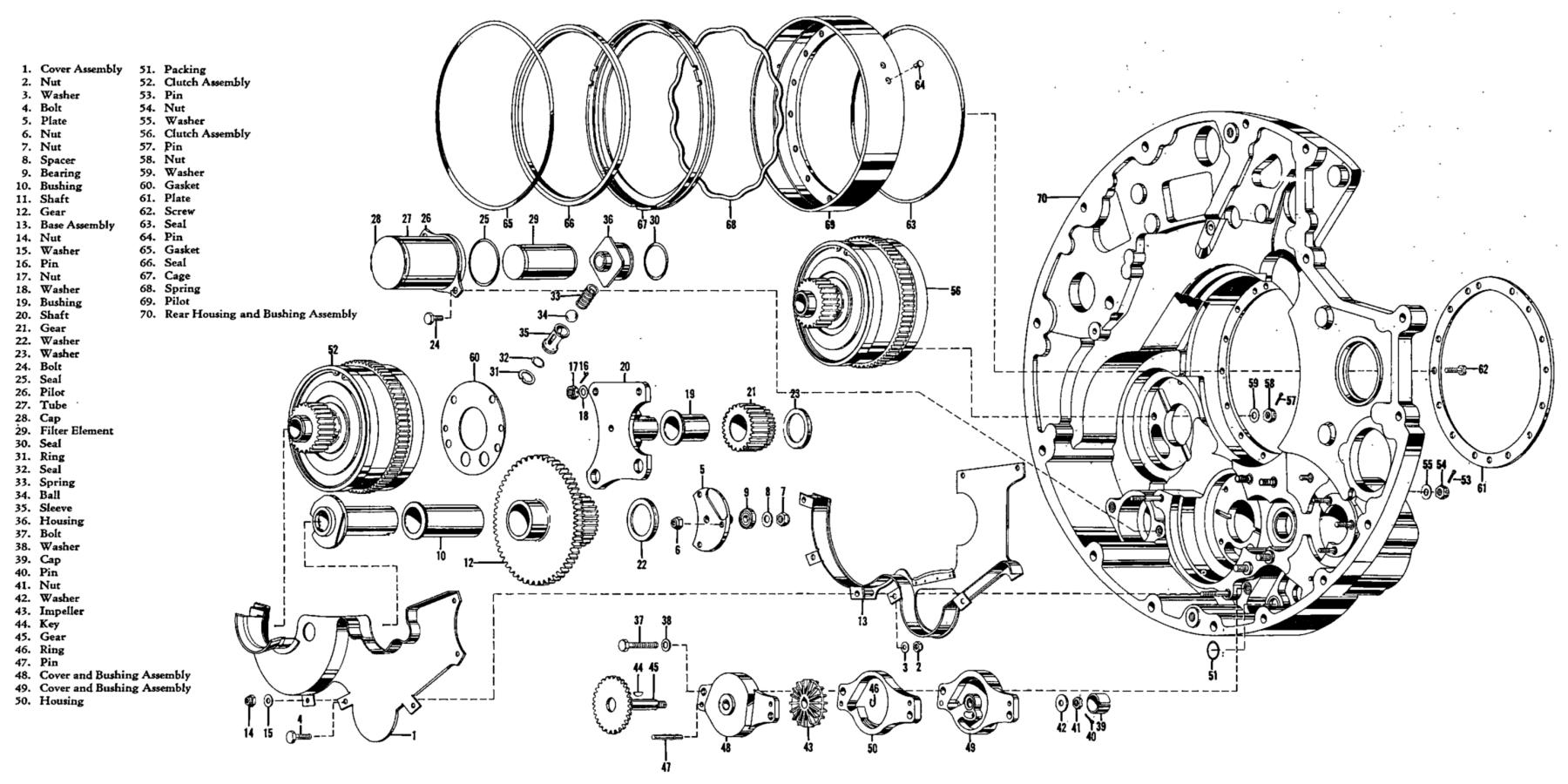 |
| Fig20. The propeller hub and propeller blade root. The cylindrical housing parallel to the axis of the prop shaft, nestled between the hub sockets, houses the shaft and worm gear from the pitch change gears. The socket insert (1) mates securely with the end of the propeller blade. The peripheral exterior teeth on the insert engage the worm dive. | Fig21. Front cover housing with number key for Fig22. | Fig22. The Power Unit Assembly. The internally and externally toothed Moveable Ring Gear is shown in the middle with pinion spider assembly (9) to left of the Moveable Ring Gear. The two pitch change clutches seated in the housing and their central output gears will mesh with the outside teeth of the Movable Ring Gear. The Feathering Motor is (1) and Brake Assembly is (9). | >Fig23. Propeller Assembly. The Power Unit containing the clutches (49) is at left. The propeller Governor Assembly (11) is at top. | Fig24. Rear Housing Assembly showing the clutches (52, 56) and exploded oil pump (37 through 50) that lubricated the propeller pitch change gear trains. The rear housing (70) is a machined work of art. |
There were also practical challenges to maintenance of the propulsion system on the C-133. The outboard engines were seventeen feet eight inches off the ground, and the propellers weighed 1,300 lb. A special propeller hoist (Pier ST1641) and work stands were designed for the C-133 by Douglas and allowed an experienced crew to change a propeller in about 4 hours (Fig25, Fig26). The propeller alone required 96 Special Tools and 31 different Technical Order manuals to maintain and repair.
 |
 |
| Fig25. The Douglas-designed propeller ST1641 pier and work stand used for propeller maintenance and removal. It appears the propeller stub mount on the pier can be rotated 180°, and then moved off the stub and into place via the overhead crane. The propeller assembly weighed 1,325 lb. (Cal Taylor/USAF) | Fig26. The propeller on right reveals the aft end (engine side) of the propeller assembly filled with electromechanical devices. The propeller on the left may be having its propeller nut torqued down with a hydraulic torque wrench. The propeller nut requires at least 2,300, and no more than 2,500 pound-feet of torque to secure. (Cal Taylor/USAF) |
The life of the C-133, and the propellers especially, is a history of tragedy. Fifty C-133 aircraft were built, nine aircraft had crashed and one was destroyed on the ground during the 15 years of active duty. Unending electrical problems affecting propeller control, propeller imbalance and synchrophasing issues caused vibration so severe a person or tool boxes would skitter across the cargo floor like electric football players and dangerously fatigue humans as well as the airframe. Underperforming engines required controversial airframe weight reduction to meet performance goals, external fuselage hoop bands to reinforce the lightened airframe, and a myriad of other issues made for a troubled life. Add into that mix the challenging operational environments and the pressing demands of the Cold War summed to wreak havoc on the airplane and the men who flew and maintained her. All of these challenges are well documented in Cal Taylor’s excellent book.
As a side note, Curtiss Wright succeeded in putting their CT634S Turboelectric propellers on the early Lockheed C-130 Hercules aircraft, but the propeller was once again dogged by problems. Curtiss was also in competition for their Turboelectrics to drive the Lockheed L-188 Electra, which first flew in December of 1957. When the President of Eastern Airlines, Eddie Rickenbacker, examined the disassembly of the Curtiss Turboelectric propeller, he infamously quipped “It looks like Rube Goldberg lives in there”. Eastern did not select the Curtiss propellers, choosing instead the Aeroproducts A6441FN-606 propellers.
The Last Flying Curtiss Turboelectric Propellers
Amazingly, Douglas C-133B, serial 56-1999, registered N199AB, continued to fly as a private commercial transport aircraft carrying outsized cargo in Alaska long after the USAF retired their C-133 fleet in August of 1971. Owned by Maurice Carlson, it is N199AB that had the last flying Curtiss Turboelectric propellers, making her final flight from Alaska to Travis Air Force base on August 30, 2008. A gentleman named Ken Kozlowski was responsible for keeping this complex aircraft flying for 37 years beyond its retirement from the military.
The final flight is documented with an excellent photo mosaic with interesting technical detail by Mark M.
Some spectacular documentary video of the final flight and an amateur video of the landing (the sound is incredible) has been made available.
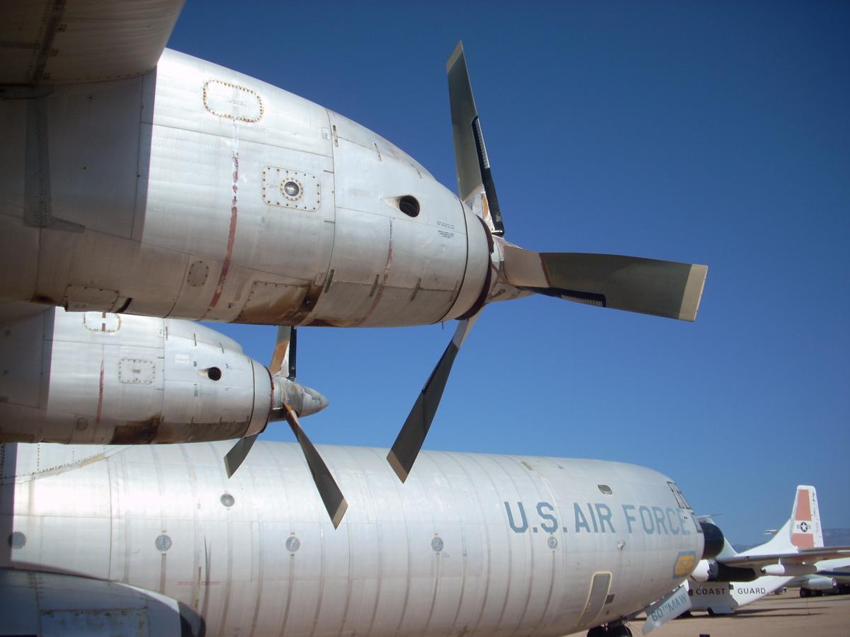
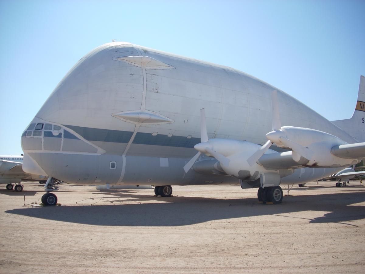
There are several C-133 aircraft preserved in museums: NMUSAF, Dayton, Ohio; Pima Air and Space Museum, Tucson, Arizona; Air Mobility Museum, Dover AFB, Dover, Maryland; Travis AFB Museum near Fairfield, California (Fig27, Fig28). Additionally, the T34/Curtiss Turboelectric propeller YC-97J (52-2693) that was converted to the NASA Turbo Super Guppy survives at the Pima Air and Space Museum Tucson, Arizona (Fig29).
When the AEHS Convention #3 visited the back lot of the New England Air Museum in 2006, I noticed a massive propeller hub moldering in the weeds. There is little doubt this forlorn artifact was one of the Curtiss Turboelectric propellers on C-133B, 59-0529 destroyed by a tornado on 3 Oct 1979 (Fig30).
 |
|
 |
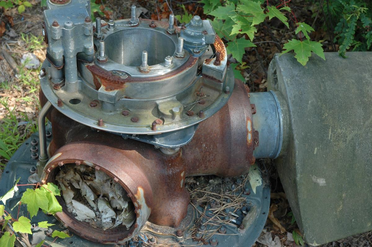 |
| Fig27. Douglas C-133B, 59-0527, in residence at the Pima Air and Space Museum, Tucson, AZ, USA. (Fey) | Fig28. Vertical blade shows the fiberglass reinforcement delaminating from the ageing cuff. Douglas C-133B, 59-0527. (Fey) | Fig29. Boeing YC-97J (52-2693) converted to the NASA Turbo Super Guppy rocket component transport that is powered by T34/Curtiss Turboelectric propeller system. Aircraft is shown cocooned in outdoor storage at the Pima Air and Space Museum, October 2017. (Fey) | Fig30. The distinctive Curtiss Turboelectric hub, likely off C-133B (59-0529), destroyed by tornado at the New England Air Museum on 3 Oct 1979. Photo taken July 2006. (Fey) |
Acknowledgements
I’d like to thank Bob Stenger for generously sharing his knowledge and treasure trove of technical documents with me, Cal Taylor for writing the masterful, definitive work on the C-133, and AEHS member Bruce Vander Mark for the C-133A/B manual.
References
Remembering and Unsung Giant by Cal Taylor, First Fleet Publishers, 2005.
C-133A and C-133B Flight Manual, T.O. 1C-133A-1, 15 June 1961.
Handbook Overhaul Instructions, Turboelectric Propeller Model CT735S-B102, T.O. 3E3-2-13, 10 March 1955.
Handbook Operation and Service Instructions, CT735S-B102 Turboelectric Propellers and Propeller Controls, T.O. 3E3-2-11, 15 January 1955.
Power Plant Analyzer System, Technical Manual Part Number ST4235, T.O. 33D4-6-247-1, 1 July 1965.
The Curtiss X-Planes by Francis H. Dean, Schiffer Military History, 2001.
Send mail to
![]() with questions or comments about this web site.
with questions or comments about this web site.
![]()