The Curtiss Electric Contra-Rotating Propeller System
by Tom Fey
Published 21 Apr 2021; Revised 4 Apr 2023
|
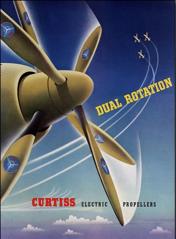
Previous AEHS articles or Convention presentations have described the theory, benefits, and disadvantages of dual rotation propellers. In brief, they offered the potential to absorb several thousand horsepower with reasonable propeller diameters, blade loadings, and tip speeds as well as simplifying the landing gear design requirements to accommodate large diameter propellers. Dual rotation propellers also had the potential to improve propulsion efficiency by 3 to 8% due to the recovery of swirl energy, and improve aircraft handling, especially at low airspeeds, by the elimination of torque. Coaxial propellers, defined as having independent drive and pitch control of two coaxially-located propeller discs, offered twin engine safety with centerline thrust, or enhanced loiter capability using just one engine/propeller. The disadvantages of dual rotation propellers included weight, complexity, noise, vibration, destabilizing side area ahead of the cg in tractor configurations, and specialized production of opposite-rotation components. Previous AEHS publications have covered the design and operation of the de Havilland (2005), Rotol (2008), Aeroproducts (2009), and Hamilton Standard Superhydromatic (2018) contra-rotating propeller (CRP) systems as well as the Curtiss coaxial propeller system (2011). |
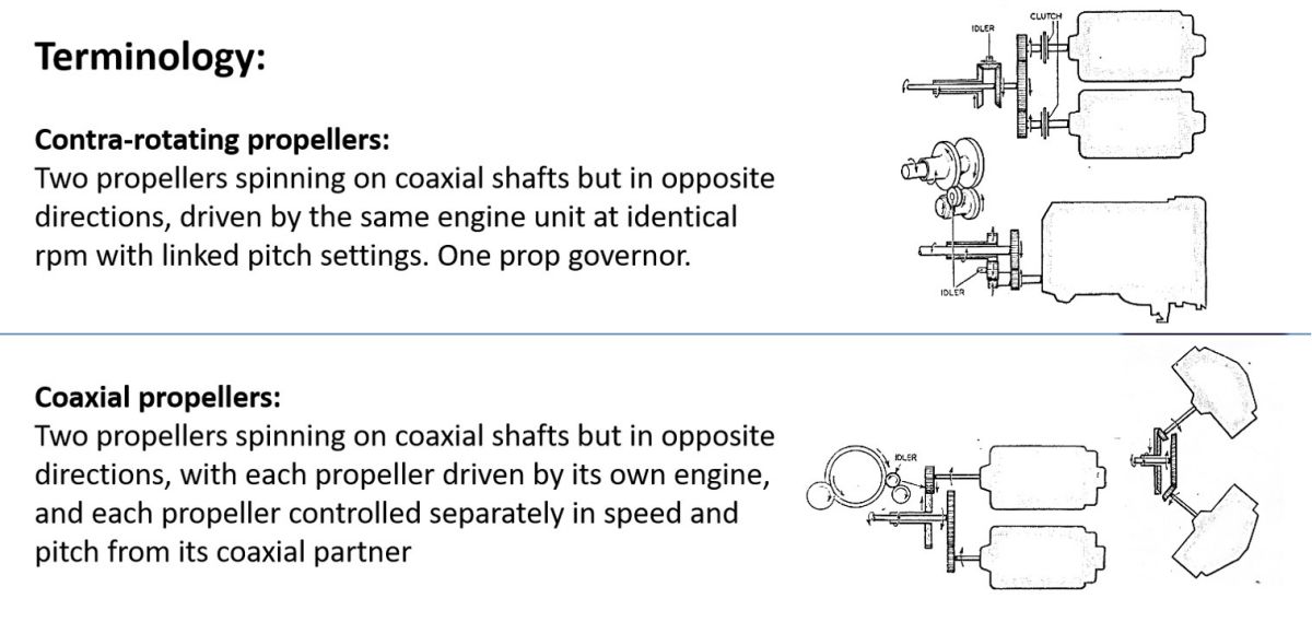 |
| Fig. 1. The control of propeller pitch for both discs is linked for contra-rotating propellers, but independent for coaxial propellers. |
Like Rotol Airscrews of Great Britain, the Propeller Division of the Curtiss-Wright Corporation, Caldwell, New Jersey, produced both coaxial propeller systems (Douglas XB-42) as well as contra-rotating (one power source drives both propellers with linked pitch control and a single propeller governor) propeller systems (Northrop XP-56, Convair XFY-1). (Fig. 1) And again, like Rotol, Curtiss produced CRP units for both piston-powered as well as turboshaft-powered aircraft. The latter systems were incredibly complex units that had to manage 5,000+ horsepower engines running at a constant speed tamed only by integrated fuel controls and propeller pitch change mechanisms. These systems were tasked with keeping engine/propeller speed variations within a few percent (± 8 rpm), regardless of load, accomplished in the bell crank-electro-hydro-mechanical age that preceded Full Authority Digital Engine Control (FADEC). They were masterpieces of engineering.
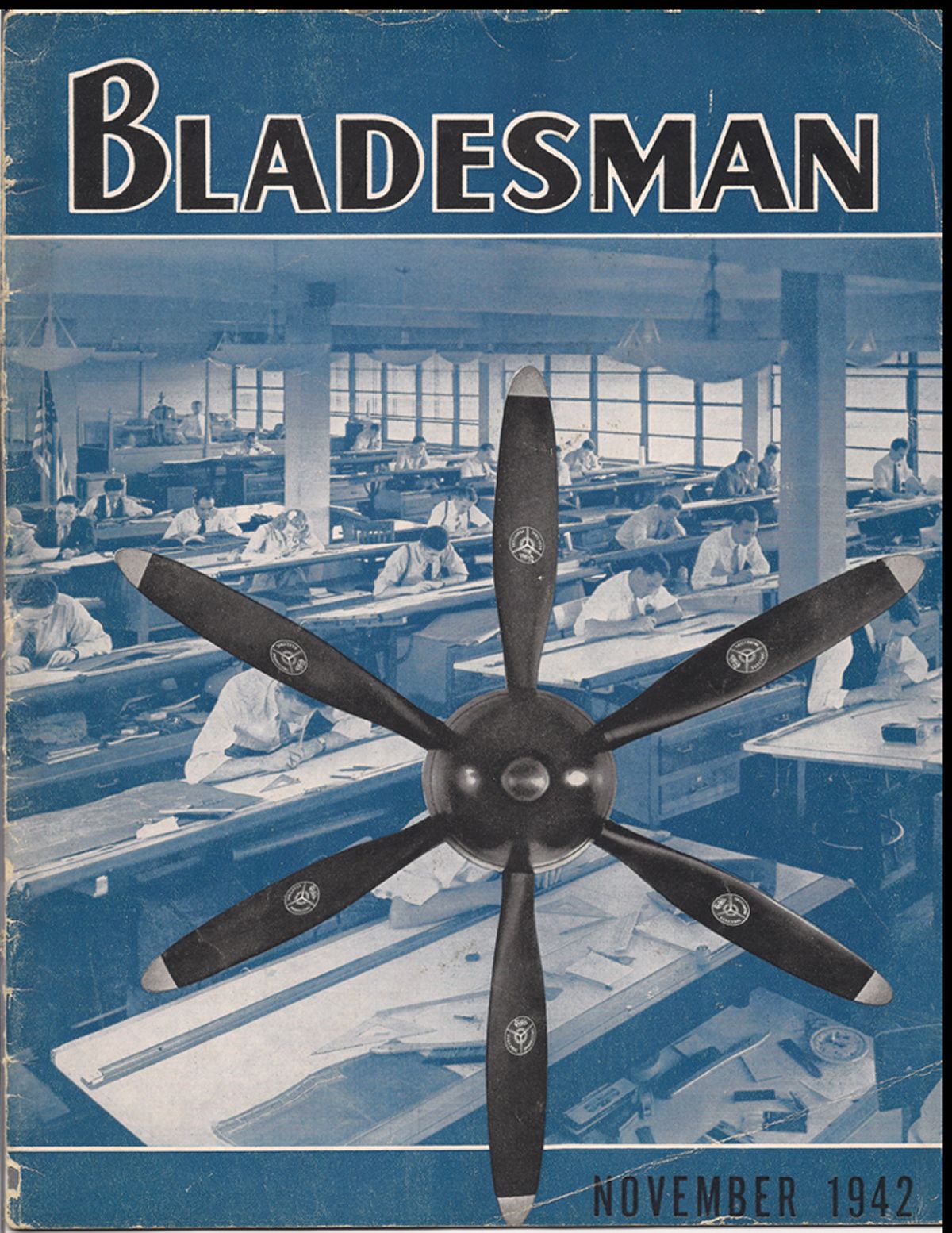
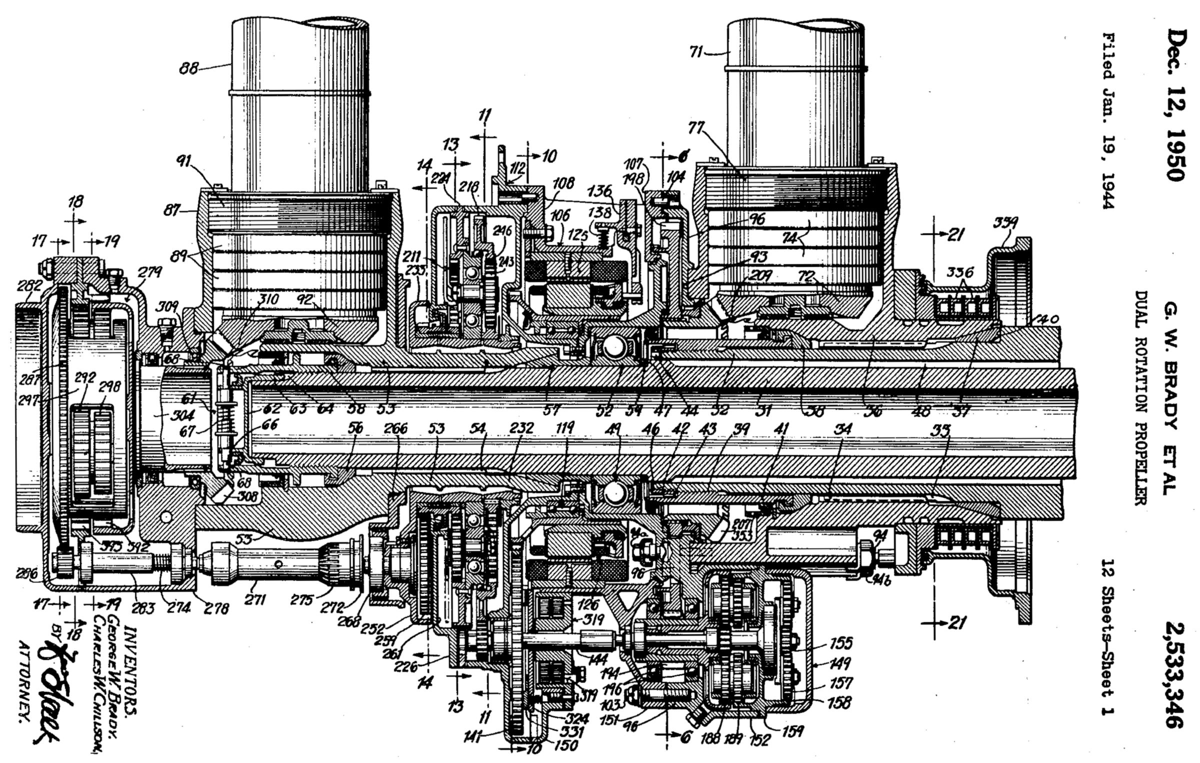
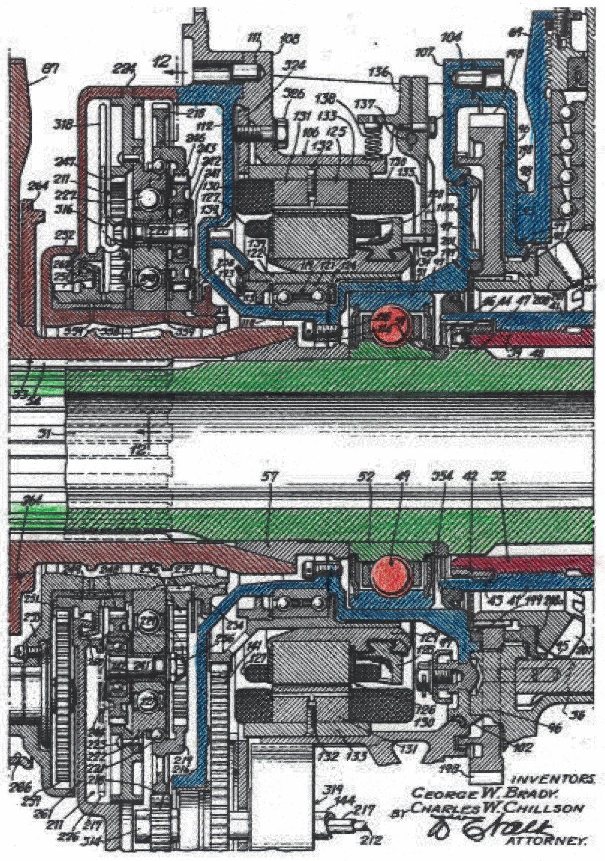
The Curtiss Electric CRP for piston engines was publicly introduced on October 15, 1942 and USAAF whirl testing began shortly thereafter. (Fig. 2) The Chief Engineer of the Curtiss Propeller Division was George W. Brady who filed a patent for the CRP design in January 1944, granted in December 1950. (Fig. 2a)
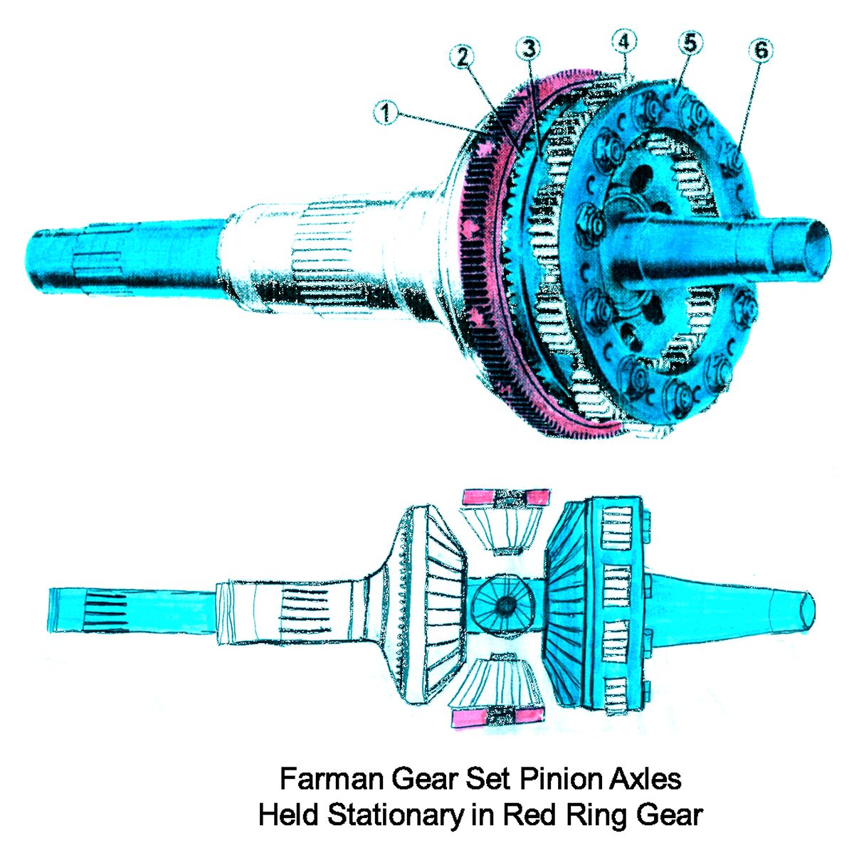
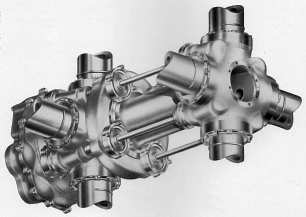
To achieve contra-rotating shafts in a geared radial engine, Pratt & Whitney developed a compact assembly that added a Farman bevel gear to the outboard side of the typical planetary gear reduction system. This reversed the rotation of the inboard component but maintained the same rpm on both propeller shafts. (Fig. 3)
The first requirement for a dual-rotation propeller system, either coaxial or contra-rotating, is that the center of the propeller hubs must be hollow to allow the extended shaft that drives the outboard propeller to pass through the center of the inboard propeller hub. For the Allies during WWII, both Curtiss and Aeroproducts produced open-bore propeller systems that were used on the Bell P-39 Airacobra where a 20 mm or 37 mm cannon to fire through the hub of the propeller. This gave these companies a head start on designing dual rotation propeller systems since the actuation system for a hollow-hub propeller was already well established. (Fig. 4)
 |
 |
 |
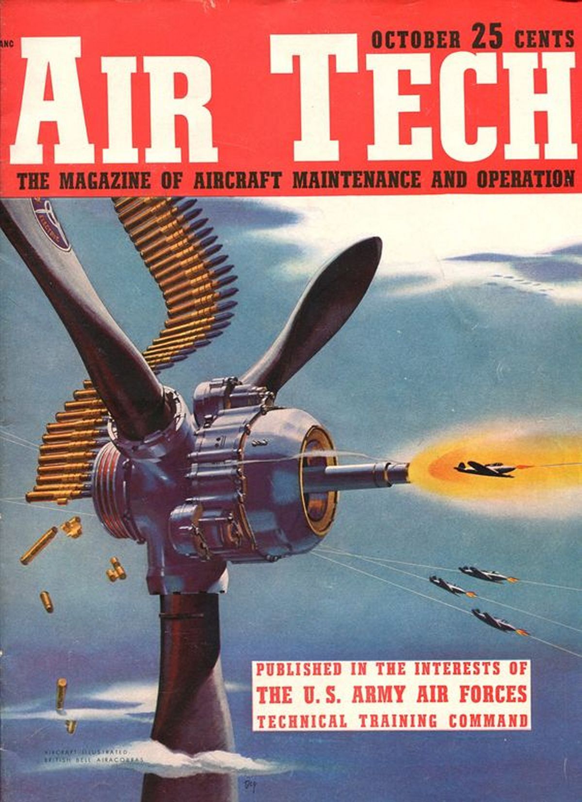 |
| Fig. 2. November 1942 issue of Bladesman, a monthly publication of the Curtiss-Wright Corporation Propeller Division, announcing the October 15, 1942 introduction of the Curtiss Electric contra-rotating propeller. | Fig. 2a. US Patent 2,533,346 for the Dual Rotation Propeller granted to George W. Brady and Charles W. Chillson of Curtiss-Wright Corporation on December 12, 1950. Extensive precision machining and a very high parts count. | Fig. 3. Pratt & Whitney Dual Rotation Reduction Gear. The contra-rotating gearbox developed by Pratt &Whitney for use on radial engines used a Farman bevel gear set on the front of a typical planetary reduction gear train. This reversed the direction of rotation of the aft component but maintained the same rpm on each shaft. Engine input is via the sun gear, and this design was used in remote gearboxes for the Northrop XP-56 and XB-35 aircraft. | Fig. 4. October 1943 Air Tech Magazine Cover, a USAAF publication, with the Curtiss Electric Model C6315SH hollow bore propeller as used on the P-39 Airacobra. |
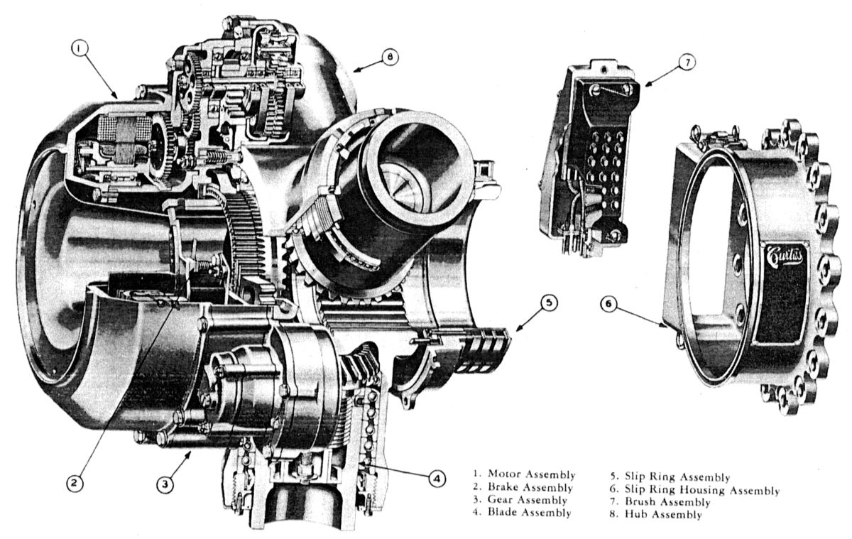
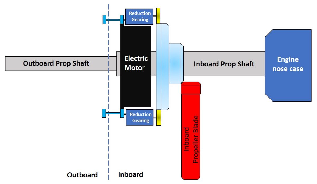
There were two key mechanical elements to the Curtiss Electric CRP system. The first was the donut-shaped, hollow bore electric motor that provided the motive force for the pitch change system, and second was the Stanley/VDM system of planetary gears that operated with the mandatory open bore and provided the mechanical transmission of a pitch change command from one propeller to a second coaxial propeller rotating in the opposite direction. This system will be described in due course.
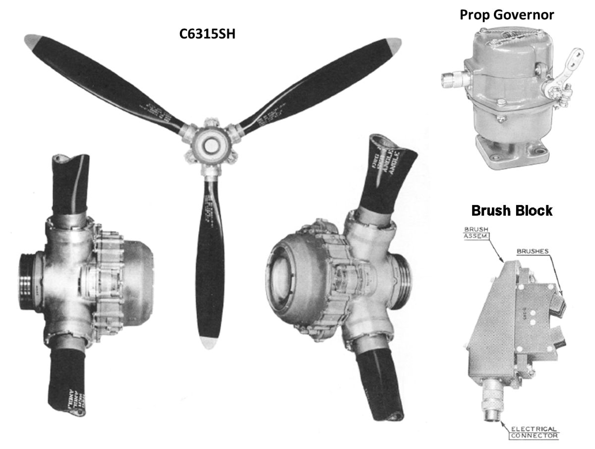
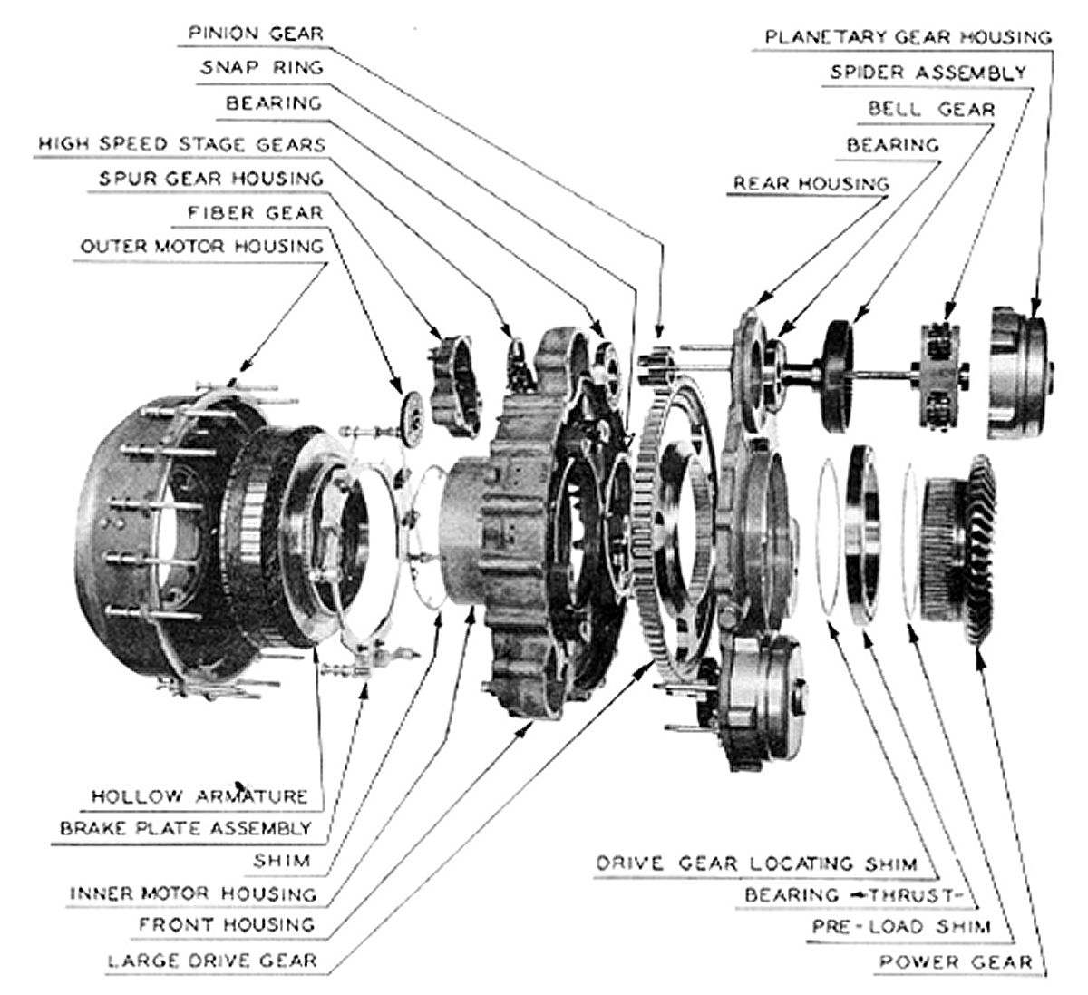
The single rotation Curtiss Electric C6315SH (Curtiss; 60 spline prop shaft size; 3 blade; 15 = 1.5 blade socket size; Steel blades, Hollow bore) used on the P-39C,-D, -L, and -M used slip rings connected to insulated brass pins situated in hollow hub mounting bolts to transmit either 12 volts (32 amp max) or 24 volts (17 amp max) current to a donut-shaped, 0.5 horsepower, reversible electric motor mounted on the front of the forged steel propeller hub. (Fig. 5) Wired in series with the motor circuit was a solenoid (12V, 35 amp max or 24V, 20 amp max) that withdrew the spring-loaded brake pad from the motor face whenever current was fed to the electric motor. This brake system locked the blade pitch in place when no current was flowing to the propeller; essentially a dead man’s switch. In contrast to the VDM propeller that used creep-resistant worm gears to rotate the base of the propeller blades, Curtiss used spur, planetary, and bevel gear trains in their propellers at the time, thus the need for a propeller brake to keep the blades from migrating back to low pitch by centrifugal twisting moment. Cam-activated low pitch stop and high pitch stop switches were incorporated in the gear train to stop the motor at the opposing ends of the pitch range. (Fig. 6) The pitch change motor used a sequence of spur and planetary gears mounted on the periphery of the hub to generate the torque required to change the pitch of the highly-loaded blades. The considerable torque generated by the relatively large diameter of the electric motor was multiplied further by the 2,298 to 1 gear reduction ratio. The motor had to spin 191 revolutions to achieve the full 30° range of blade pitch change. The entire reduction gear train is mounted in ball bearings, sealed, and immersed in lubricating oil. (Fig. 7)
The actual reduction gear train is illustrated in Figure 8 The motor spur gear in blue meshes with the red-to-green-to-yellow series of spur gears. The gear on the opposite end of the yellow shaft acts as the sun gear that drives blue planet gears that drives the red bell gear. And finally, the spur gear atop the bell gear drives the periphery of the green power ring gear. The beveled gear surface of the power gear drives all three blade segment gears in synchrony. Needless to say, there is a lot of precision machine work in the Curtiss assembly.
 |
 |
 |
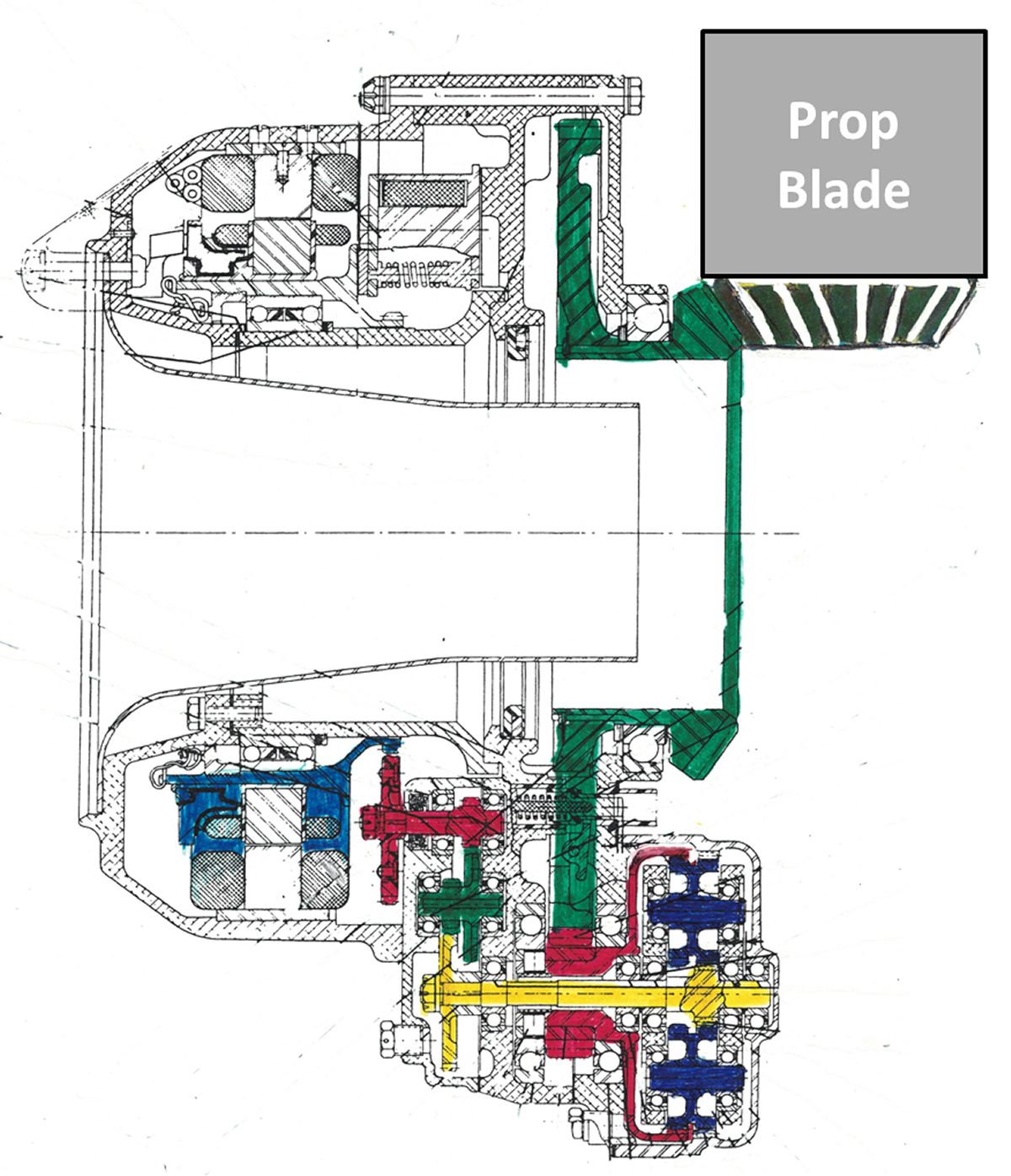 |
| Fig. 5. The Curtiss Electric hollow bore electric propeller Model C6315SH showing the constant speed propeller governor and brush block that transfers electrical signals to the propeller via hub-mounted slip rings. | Fig. 6. Cutaway of the Curtiss electric C6315SH propeller. This propeller provided the basic design for the inboard component of the Curtiss contra-rotating propeller units. | Fig. 7. Exploded photograph of the electric motor and concentric reduction gearing elements for the Curtiss C6315SH hollow bore propeller. Reduction ratio was 2,298 motor revolutions per to 1 revolution of the propeller blade in the hub socket. However, maximum pitch travel is 30°. | Fig. 8. Colorized side view of the Curtiss C6315SH propeller gear reduction path. The motor drives three sequential sets of spur gears to a planetary bell gear system that drives the Power gear. The Power gear meshes with segment gears on the three propeller blades to effect pitch change. |
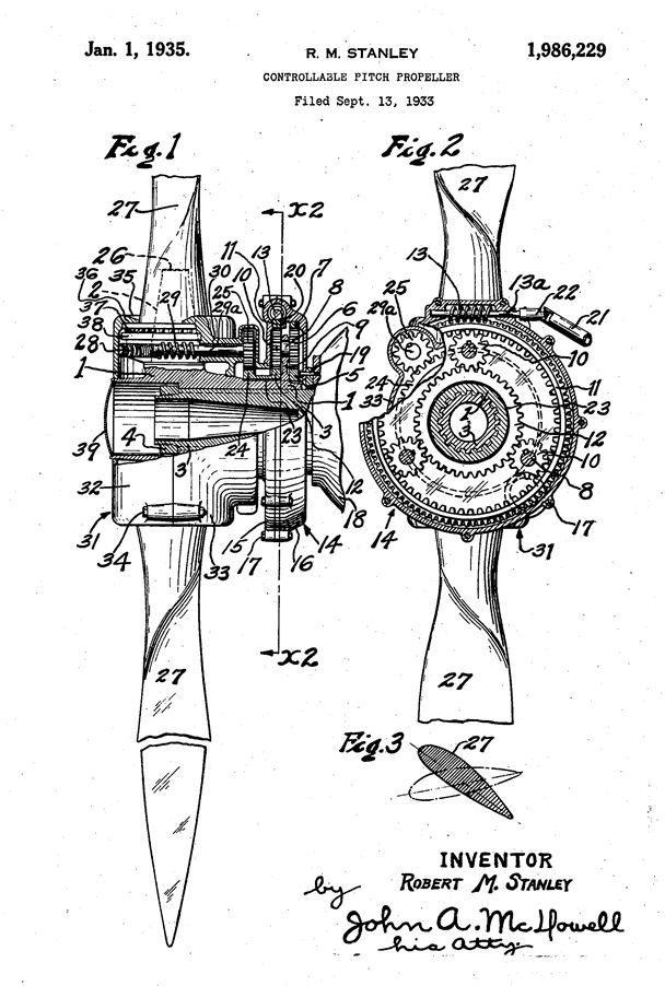 |
| Fig. 9. The Robert M. Stanley US patent 1,962,289 granted January 1, 1935, describing a planetary gear system for changing the pitch on a rotating aircraft propeller. |
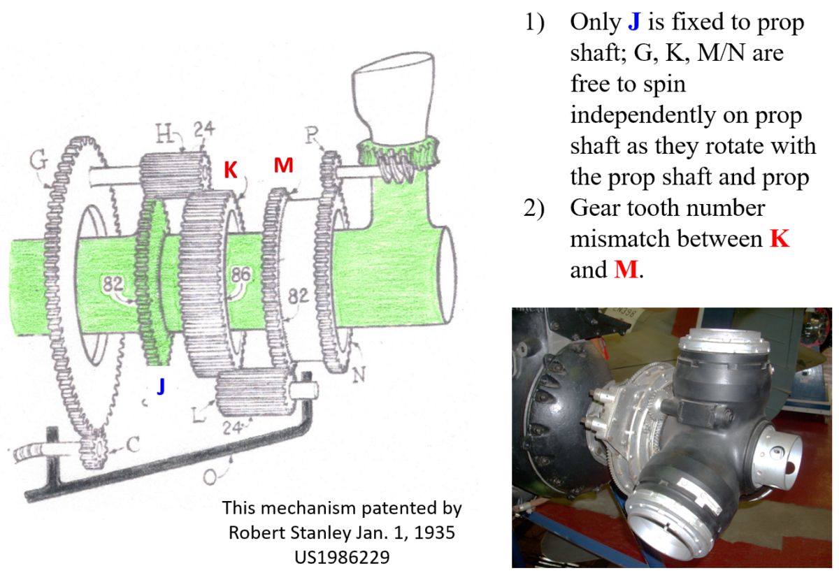 |
| Fig. 10. Stanley/VDM (Vereinigte Deutsche Metallwerke) pitch change operating schematic of the planetary gearing system used in the German hollow bore VDM propeller. Briefly, an electric motor drives pinion C to rotate gear G that re-indexes the planetary gear train. This results in gear N turning gear P that rotates a worm gear at the base of the blade to effect pitch change. A VDM propeller hub is shown in the photograph at the bottom right. |
The Curtiss Model C(57)615SP-A contra-rotating propeller utilizes the basic design of the P-39’s C6315SH single rotation propeller for the inboard component of the CRP but with a few modifications. To minimize the distance between the blade discs and improve braking efficiency, the friction surfaces of the pitch brake has been moved from the back of the motor on the P-39 prop to friction faces attached to the three reduction pinions on the CRP power unit. Eighteen springs closed the brake and three solenoids opened it. The pitch of the outboard propeller is mechanically slaved in lock-step to the inboard component via a system of planetary gears patented for single rotation propellers by American Robert M. Stanley in 1935 (Fig. 9). This planetary gear system was used by VDM in their hollow-bore electric propeller that was used on great majority of the German aircraft in WWII, including the Messerschmitt Bf-109, Focke-Wulf Fw-190, Dornier Do-217, and Heinkel He-177.
The operational schematic of the Stanley system is illustrated in Figure 10. Importantly, only gear J is firmly attached to the propeller shaft. Shafts holding gears L and C are stationary, held by the engine housing; C is the pitch change input gear and L is free to spin on its own axis, but does not orbit. All the other gears are free to both spin on their own axis as well as orbit on their carriers. The mismatch in gear tooth number between J-H-K is returned back to neutral by the identical gear tooth number mismatch between K-L-M, thus the gears can be thought to “run in place” with no indexing change, or load, occurring until a pitch change is commanded. The movement of G “re-indexes” the downstream gears in the train, ultimately causing N to rotate P, which drives the blade pitch worm gear.
As already described, the gear reduction train to change the pitch of inboard propeller blades of the C(57)615SP-A CRP is essentially identical to the open-bore Curtiss C6315SH used on the P-39 and shown schematic form in Figure 11.
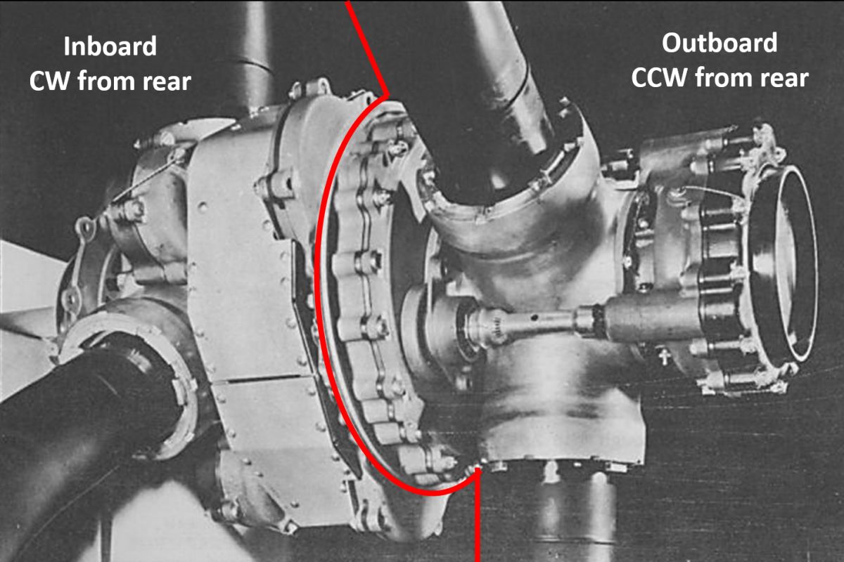
Now considering the outboard component of the Curtiss CRP, the mechanical power for changing the pitch on the outboard propeller is taken off a spur gear connected directly to the electric motor of the inboard component. Three torsion shafts that transmit the pitch change from the inboard to the outboard component. This means the outboard component must deliver the same 2,298 to 1 reduction ratio as the inboard prop for the blade discs to remain in lock step. This reduction is achieved by the Stanley gears and the speed reducer attached to the center of the outboard prop hub. The two components of the C(57)615SP-A CRP are delineated in Figure 12, and the complete propeller shown on the electric whirl test stand in Figure 13.
 |
 |
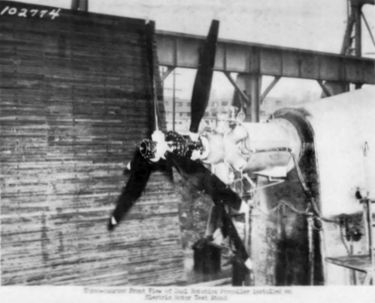 |
| Fig. 11. Curtiss C(57)615SP-A Inboard Pitch Change Gear Train. A donut shaped electric motor drives reduction gear trains that rotate the Power ring gear, thereby changing the pitch on all three propeller blades via segment gears on the blade bases. | Fig. 12. A Curtiss contra-rotating propeller assembly mounted on an aircraft. As demarcated by the red line, the inboard component containing the electric motor rotates clockwise while the outboard component that contains the Stanley gears rotates counter clockwise as viewed from the rear. | Fig. 13. Curtiss C(57)615SP-A contra-rotating propeller is shown on the electric whirl test stand. What looks to be a radial engine is the special CRP gearbox. This testing provides data for thrust and blade deflections at various settings of pitch, horsepower, and rpm. Endurance testing and overspeed to 130% and horsepower levels exceeding 160% of rated power were performed. A maximum static thrust of 6,760 lb was achieved at 1,386 rpm on 2,832 horsepower, or 2.4 pounds of thrust per horsepower. |
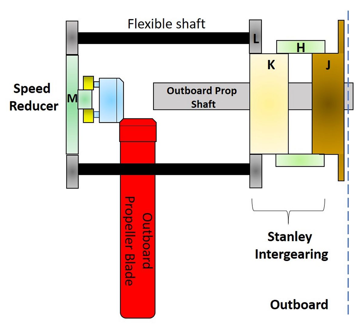
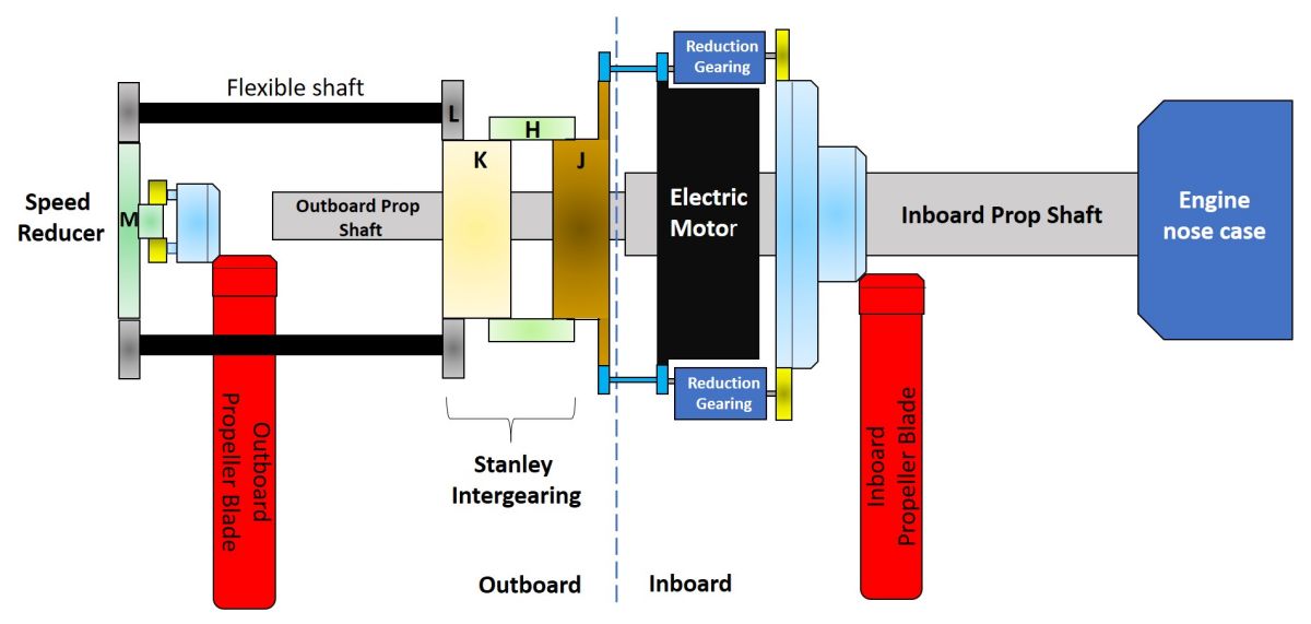
Shown schematically in Figure 14, the sun gear of the Stanley gear train is driven via spur gear and torsion shaft off the motor of the inboard component, fulfilling the function of the Gear J in the Stanley/VDM schematic in Figure 8. This sun gear drives the rest of the Stanley gear train that is housed entirely in the outboard component. There are three flexible drive shafts (L) to share the loads coming from the Stanley gear train up to the speed reducer assembly mounted on the center of the outboard hub. These three flexible transfer shafts, as well as the three torsion shafts bridging the inboard and outboard components, are flexible to compensate for induced misalignments and inertia of the numerous precision gear train components whirling on overhung propeller shafts in opposite directions. The pinions of the flexible shafts engage the perimeter of a central spur gear in the speed reducer. This spur gear in turn drives a single stage planetary gear, and the planet gear carrier is splined to a spiral bevel gear that meshes with the segment gears on the base of the blades. (Fig. 15) The presence of Zerk fittings indicates the outboard speed reducer runs in grease.
 |
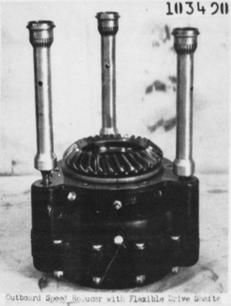 |
| Fig.14. Curtiss Outboard Pitch Change Gear Train. Gears are represented by the shaded rectangular boxes and the letter designations refer to the functionally equivalent gears in Figure 8. Drawing is not to scale. | Fig. 15. Speed reducer assembly for the outboard propeller of the Curtiss C(57)615SP-A CRP. The three shafts run from the Stanley gears up to the spur and planetary reduction gear sets in the speed reducer. The central spiral bevel gear engages the segment gears on the base of the propeller blades. |
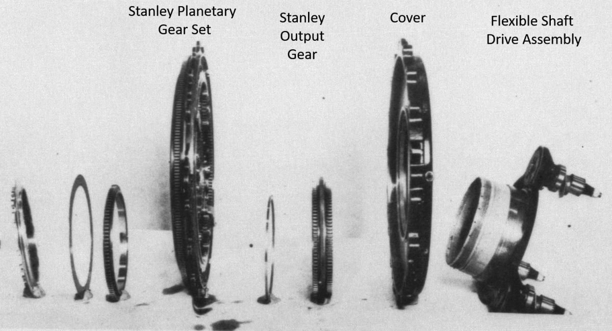
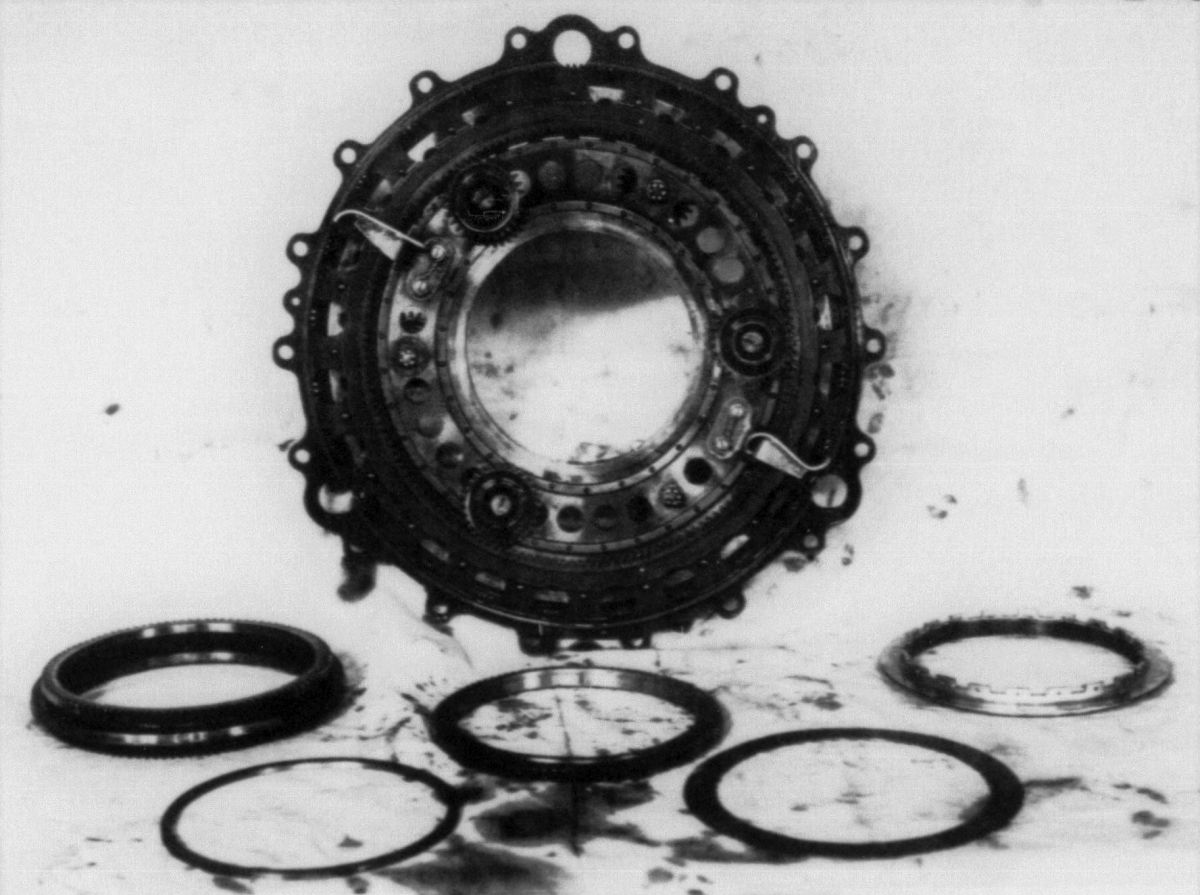
The inboard and outboard reduction gear trains of the C(57)615SP-A CRP are shown schematically in Figure 16. The actual Stanley gear train components are shown in Figures 16a, 16b, 16c, and 16d. The unit ran immersed in oil.
 |
 |
 |
 |
 |
| Fig. 16. Curtiss C(57)615SP-A Contra-Rotating Propeller Pitch Change Gear Train. Motive power supplied by an electric motor on the inboard component. Reduction gearing contained in both the inboard and outboard components provides the torque to change the pitch of the six total blades in synchrony. Gears are represented by the shaded rectangular boxes and the letter designations refer to the functionally equivalent gears in Figure 8. Drawing is not to scale. | Fig 16a. Components of the Stanley gear train in assembly sequence, left to right, inboard to outboard. | Fig 16b. Inboard face of the Stanley gear set. Coupler from the electric motor acts as the sun gear for this assembly. | Fig 16c. Outboard face of the Stanley gear set. These gears ultimately drive the three pinions of the flexible shafts that run to the speed reducer. | Fig 16d. Underside of the Flexible Shaft Assembly. The pinions are driven by the Stanley gear set and rotate the flexible shafts. |
 |
| Fig. 17. Intershaft bearing #49 is shown in orange. The inner race seats on the outboard propeller shaft (green) while the outer race is located on the inboard propeller hub (blue). The inboard propeller shaft is shown in dark red and the outboard propeller hub to the left in brown. |
Common to all dual rotation propeller systems, whether coaxial or contra-rotating, an intershaft bearing was used take up the radial loads placed on the overhung coaxial shafts by the propellers during operation. The inner race of bearing sat on the outboard propeller shaft while the outer race engaged a relief on inboard hub. (Fig. 17) The contra-rotating C(57)615SP-A propeller unit weighs 739 pounds.
There is a complicated art and science to selecting blade diameters, blade area, blade pitch distributions, and relative blade pitch to best match the leading and trailing propeller discs to reduce vibration and noise, maximize efficiency, and equitably distribute blade loadings. Because of the swirl coming off the leading propeller disc, the trailing propeller disc sees an accelerated airflow as well as a modified angle of attack of the incoming airstream. Because of this, it is most common to have the blades of the trailing propeller indexed 0.5 to 2 degrees finer (lower pitch) than the blades of the leading propeller disc. It seems counterintuitive, but CRP manuals from Rotol, Aeroproducts, and Curtiss, as well as USAAF whirl testing reports, confirm this pitch differential. Indexing Curtiss propeller blades in 0.3° increments was made possible by a fine-tooth spline coupling between the final reduction gear and the power gear. Indexing of individual blades in the hub was not possible in this design, rather blades were carefully indexed, component-matched, and pinned to their segment gears at the factory.
Prop shaft spline sizes are indicated by the numbers in the parentheses of the Curtiss model number. The inboard prop hub for Curtiss C(57)615SP-A contra-rotating propeller used on the R-3350 powered Curtiss XP-62, and the R-4360-14 powered Curtiss XBTC-1, was a 70 spline; the outboard hub was a 50 spline. The Curtiss C(46)615SP-C1 propeller used in the pusher configuration for the R-2800-29 powered XP-56 had a 60 spline hub inboard and a 40 spline hub outboard. American turboshaft CRP’s typically used 80 spline shafts inboard and 60 spline shafts outboard.
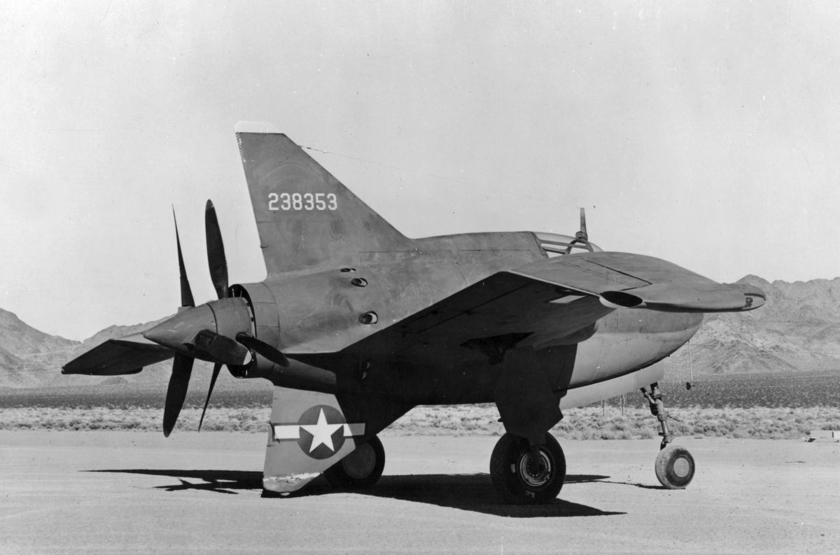
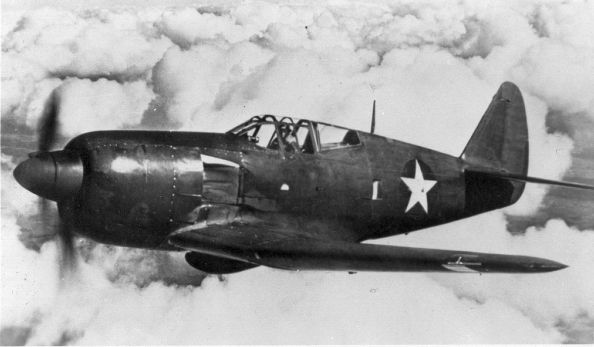
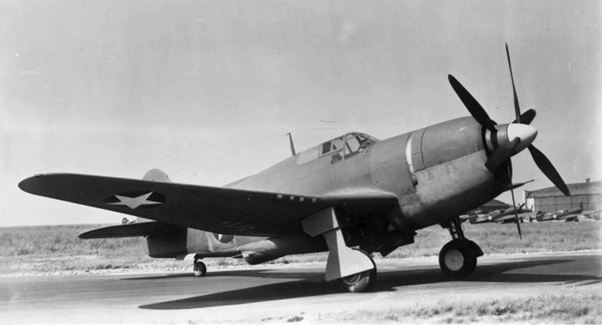
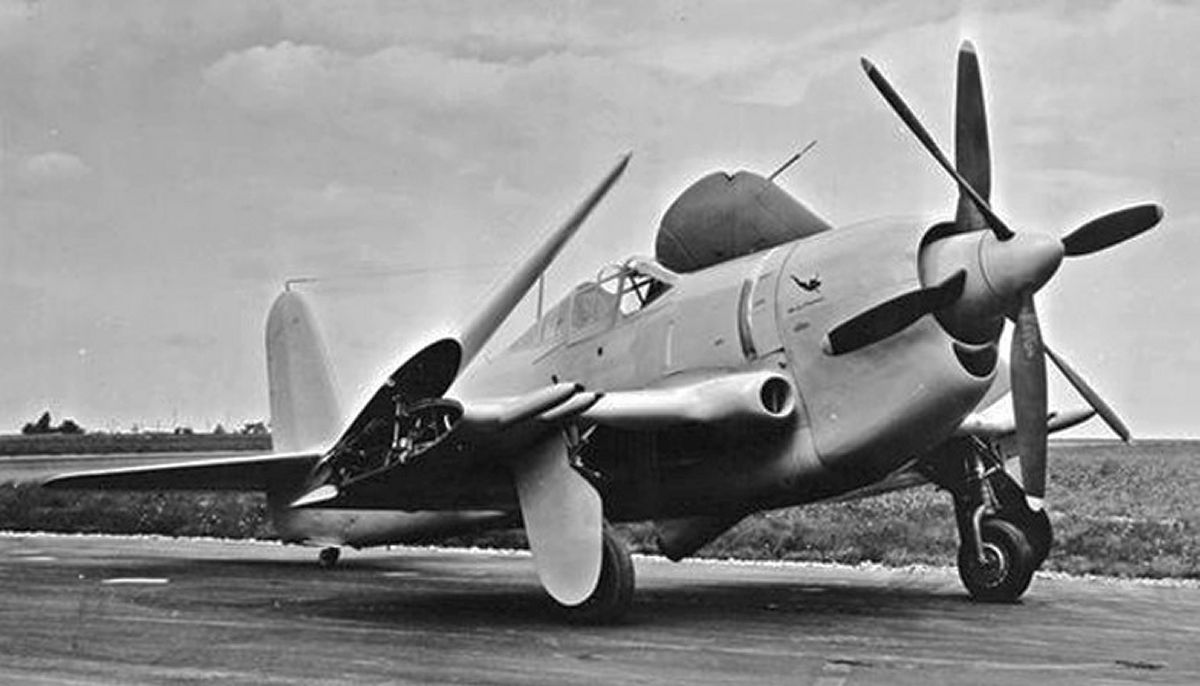
The Curtiss CRP units for piston-powered aircraft were used on the XP-56, XP-60C, XP-62, XF14C-2, and XBTC-1. (Figs 18, 19, 20, 21, 22) Notably, all but the XP-56 were Curtiss-Wright designs.
The pusher Curtiss CRP in the Northrop XP-56 flying wing suffered from vibration issues and repeated breakage of the torsion shafts that transmitted pitch change to the outboard component, but this was perhaps due to the unique propulsion system (R-2800 + cooling fan + long drive shaft + remote contra-rotating reduction gearbox + contra-rotating propellers) and not necessarily the CRP design. The Curtiss CRP flown in the R-4360-powered XBTC-1 proved harmonically incompatible with the engine and airframe, necessitating a change to an Aeroproducts AD7562 CRP. In fairness, the Curtiss XP-60C was an aircraft of many compromises, delays, and design changes, but flew and performed quite well with the Curtiss CRP. Alas, by 1943 the modest improvement in performance with the CRP didn’t justify a war time investment in the P-60 design.
In stark contrast to the Rotol and Aeroproducts CRP systems, all Curtiss CRP systems remained experimental and never entered production or military service, before, during, or after WWII.
 |
 |
 |
 |
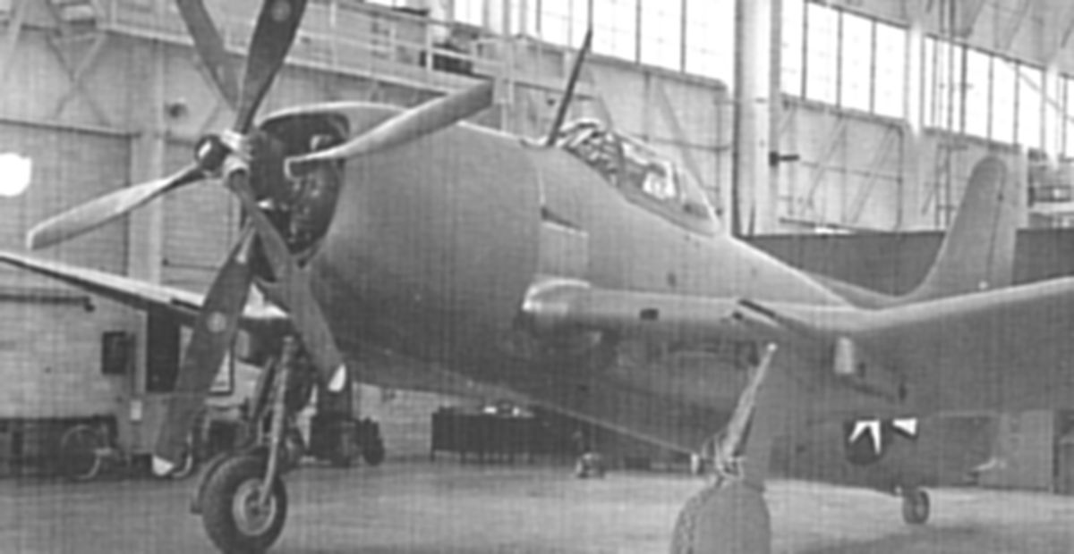 |
| Fig. 18. Northrop XP-56 propelled by the Pratt & Whitney R-2800-29 radial engine and Curtiss Model C(46)615SP-C1 contra-rotating propellers. Inboard propeller is 9 ft 7 5/8 in diameter; outboard propeller is 9 ft 6 in diameter. Aircraft was constructed of welded magnesium and propellers were jettisonable for emergency egress in flight. | Fig. 19. Curtiss-Wright XP-60C propelled by the Pratt & Whitney R-2800-53 radial engine and Curtiss Model C(46)615S-C contra-rotating propeller of 12 ft 2 in diameter. | Fig. 20. Curtiss-Wright XP-62 propelled by the Wright R-3350-17 turbocharged radial engine and Curtiss Model C(57)615S-B contra-rotating propeller diameters of 13 ft 11/16 in (fore) and 13 ft 2 1/2 in (aft). The cockpit was pressurized. | Fig. 21. Curtiss-Wright XF14C-2 for the US Navy, propelled by the Wright XR-3350-16 turbocharged radial engine and Curtiss Model C(57)615S series contra-rotating propeller approximately 12 ft 10 in diameter. | Fig. 22. Curtiss-Wright XBTC-1 for the US Navy, propelled by the Pratt & Whitney R-4360-8a radial engine and initially used Curtiss Model C(57)615S series contra-rotating propeller of 14 ft 2 in diameter. Subsequent test flying was done with an Aeroproducts AD7562-X14 CRP 13.5 ft in diameter. Two protypes were built. |
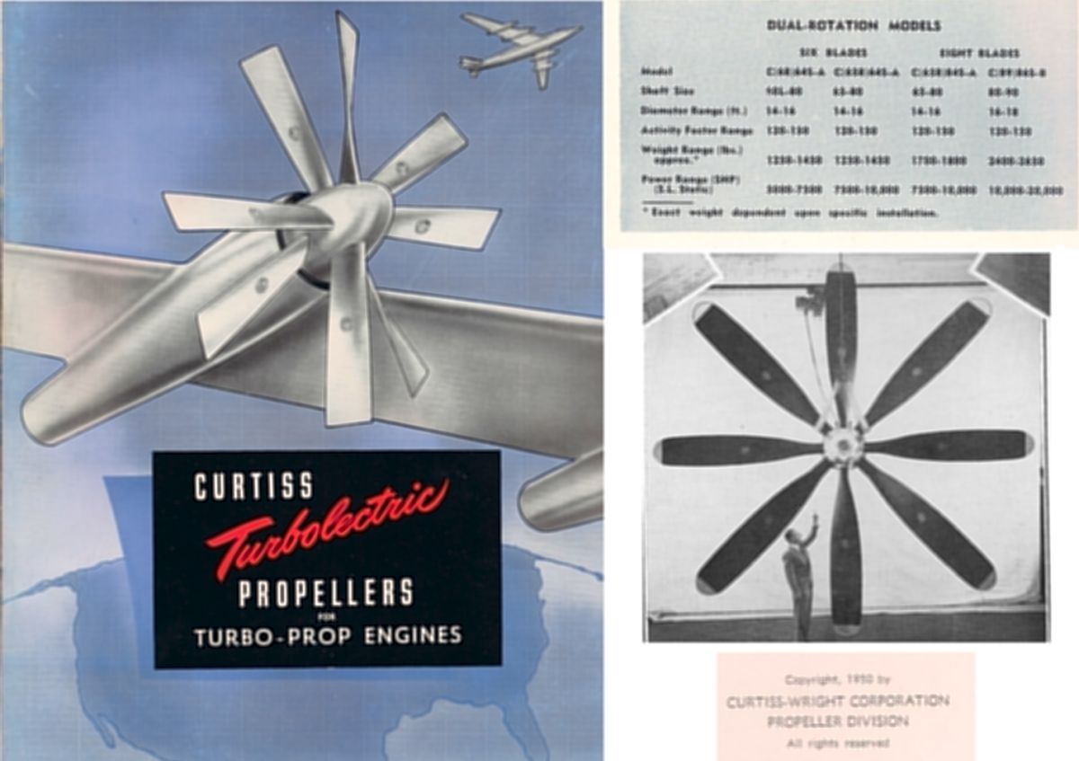
As the jet age emerged towards the end of WWII, aviation nations began to investigate turbine-driven propellers as a more efficient technology compared to the fuel guzzling, range limited, and long take off characteristics of the early turbojets. Rapid progress in the turbine field had soon production turboshaft engines generating 5,000 horsepower by 1949, and 14,000 horsepower by 1952. Harnessing this immense power, plus the unique characteristics of the turboshaft engine to both prefer constant engine speed and detest being driven by the propeller, was an incredible challenge for the propeller technology of the time. Curtiss Electric Propeller Division was a firm believer that contra-props were the future and invested heavily in designing building six and eight bladed contra-rotating turboelectric propellers of up to 19 ft in diameter. (Fig. 23).
Remarkably, the operating scheme of the Curtiss Turboelectric CRP is identical to the mechanism used for the piston-powered CRP described above except for the source of motive power and the complexity of the propeller governor. Because of the gargantuan centrifugal twisting moments of large and heavy blades compelling the blades towards low pitch, electric motors were nearing the practical limits of their ability to drive the pitch change mechanism. And more importantly, the large reduction ratios required to produce the necessary torque via electric motors, as well as the inertia in the system, meant that these propellers were rather slow acting, which was a huge disadvantage when trying to control the rpm of a screaming turbine to within a few percentage units using primarily changes in propeller pitch.
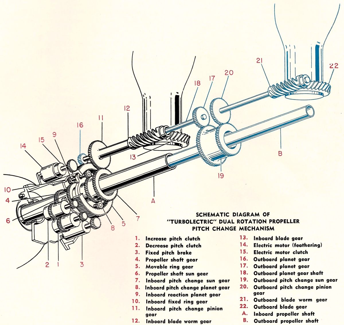
The Curtiss solution was to use the vast power of the propeller drive shaft itself as the power source for pitch change. (Fig. 24) This was accomplished by having a spur gear sleeved to the prop shaft that would act through a gear machined in the body of an electrically-operated clutch pack. The central shaft exiting the clutch pack would act through a pinion to operate the planetary gears of the Stanley pitch-change mechanism. (Fig. 25) There were separate clutch assemblies for increase pitch, decrease pitch, propeller brake, and feathering motor. Like a master pianist, the propeller governor would activate and deactivate the various clutches at the appropriate times to maintain the proper engine/propeller speeds via pitch change. It was an extremely demanding service for the clutches, but they provided the rapid pitch change rates required by the application. It took some time to design and schedule the propeller governor to minimize actuation delays, manage the inertia/momentum in the system, and hunting due to switching hyperactivity.
 |
 |
 |
 |
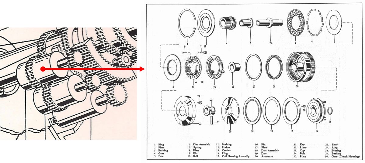
| Fig. 23. Curtiss-Wright Propeller Division brochure from 1950 showing an 8 blade, 19 ft diameter Turboelectric CRP as well as descriptive information for six and eight blade CRP units capable of handling up to 20,000 horsepower. | Fig. 24. Schematic diagram showing the pitch change system for the contra-rotating Curtiss Turboelectric propeller. Motive power for was extracted from the propeller shaft via electronically activated clutches. In contrast to the Curtiss CRP’s used in piston-powered applications, the Turboelectric propellers used on turboshaft engines utilized worm gears at the base of the blade to change pitch. | Fig. 25. Exploded parts diagram of a Curtiss pitch change clutch unit used on the single rotation CT35S Turboelectric propeller on the Douglas C-133. The when energized, the coil (15) retarded a rotating armature (20) that, through a spur-type planetary gear system (17.18.19), turned a ball ramp force multiplier (13,25) to compress the clutch plates (5,6) axially together and engage the clutch to drive the output pinion gear (4). The pitch change clutches ran in oil; the brake clutch ran dry. | Fig. 26. Drawing of the eight blade Curtiss Turboelectric contra-rotating propeller. |
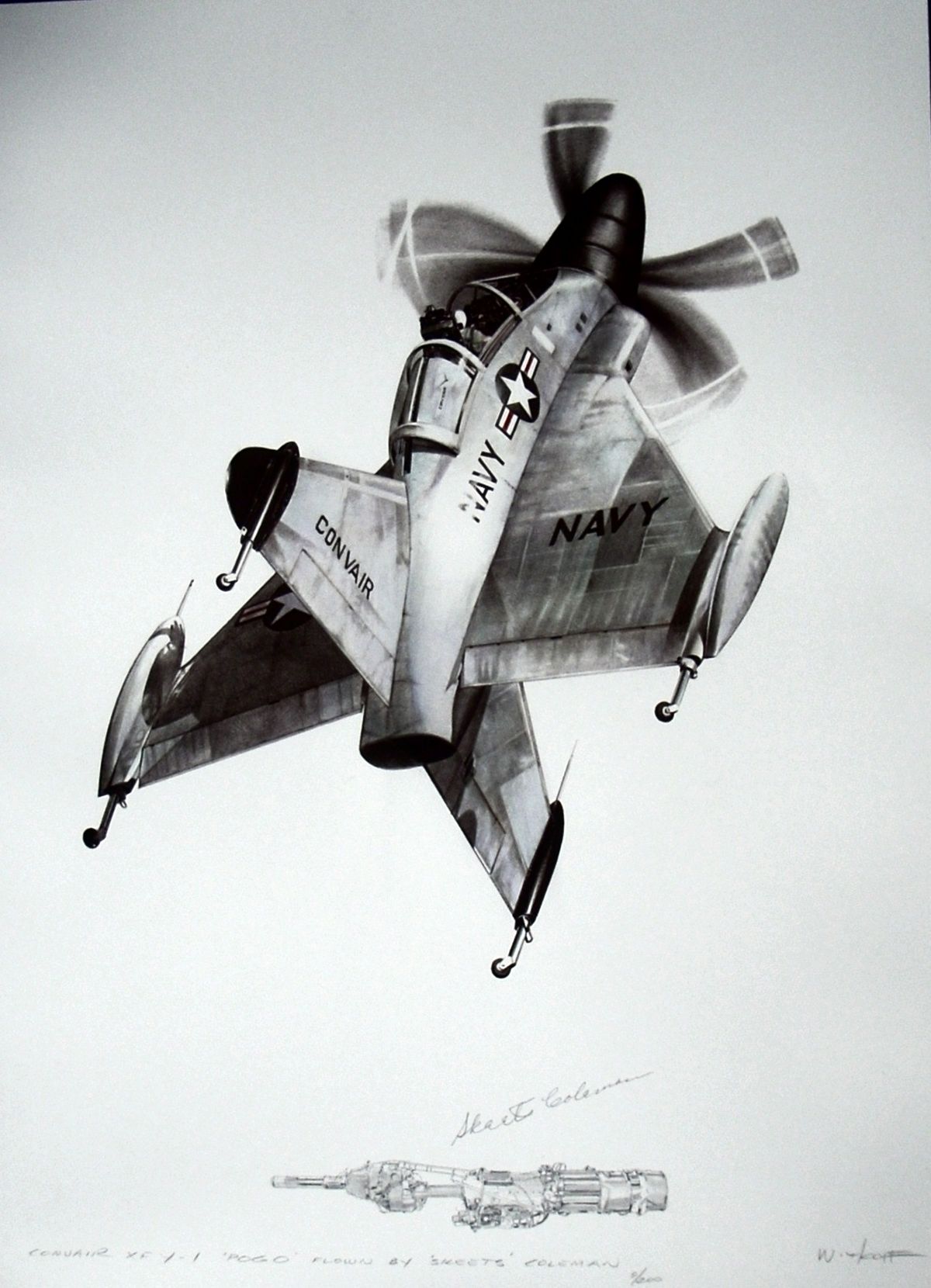
Perhaps the crowning achievement of precision propeller control was the contra-rotating Curtiss Electric C(6L8)64S-A propeller used in the Convair XFY-1 and Lockheed XFV-1 “Pogo” aircraft during the early 1950’s. (Fig. 26, 27, 28) These aircraft were designed as vertical takeoff and landing point defense fighters and were powered by the Allison T40-A14 turboprop engine of 5,830 equivalent shaft horsepower. (Fig. 29). To accommodate the horsepower, an 80 spline hub was used on the inboard component and a 60 spline hub on the outboard propeller. The propulsion system generated in excess of 17,000 pounds of static thrust. (Fig. 30) The XFY-1 demonstrated hovering capability with full transition flight occurring on November 4, 1954. This could only be achieved by CRP’s as torque from a single rotation propeller could not otherwise be managed.
The ability to modulate engine power while at a constant engine speed via propeller pitch and fuel control with a finesse that allowed not only hovering flight, but fine and yet rapid control of descent rate was an astonishing accomplishment in the very demanding, zero airspeed environment. This flight regime required a highly skilled pilot, and only one pilot, aeronautical engineer, Marine reservist, and Convair test pilot James “Skeets” Coleman, achieved transitional flight. While the Allison T40 with Aeroproducts CRP units had terminal problems in typical aircraft applications (Douglas A2D Skyshark; Convair R3Y Tradewind; North American XA2J-1 Super Savage), it should be noted that the T40 with the Curtiss CRP performed without accident or loss of life during the XFY-1, XFV-1, and Hiller X-18 programs.
As turbojets evolved to more efficient turbofans, the need for very large propeller driven aircraft waned, sounding the death knell for American contra-rotating propeller systems. Curtiss Electric’s last CRP effort was an eight bladed behemoth 18 ft 3 inches diameter for potential use in the unbuilt, four engine Douglas XC-132 tanker/transport powered by the Pratt & Whitney T57 turboshaft engine of 15,000 horsepower. (Fig. 31) The T57 was flown in a test bed but used a single rotation propeller.
 |
 |
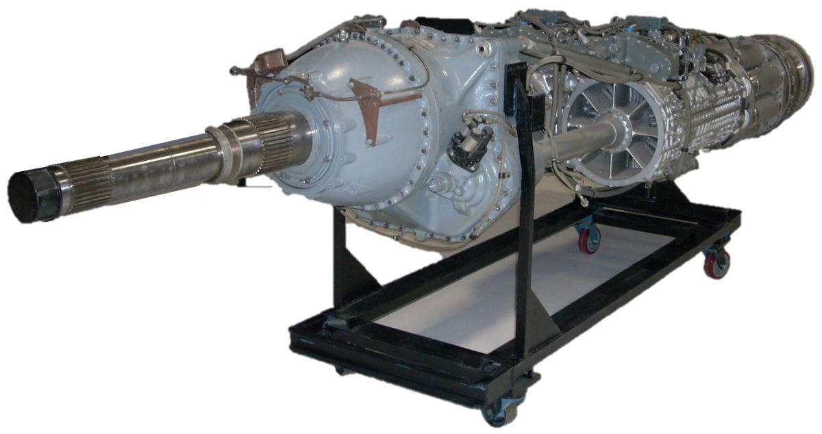 |
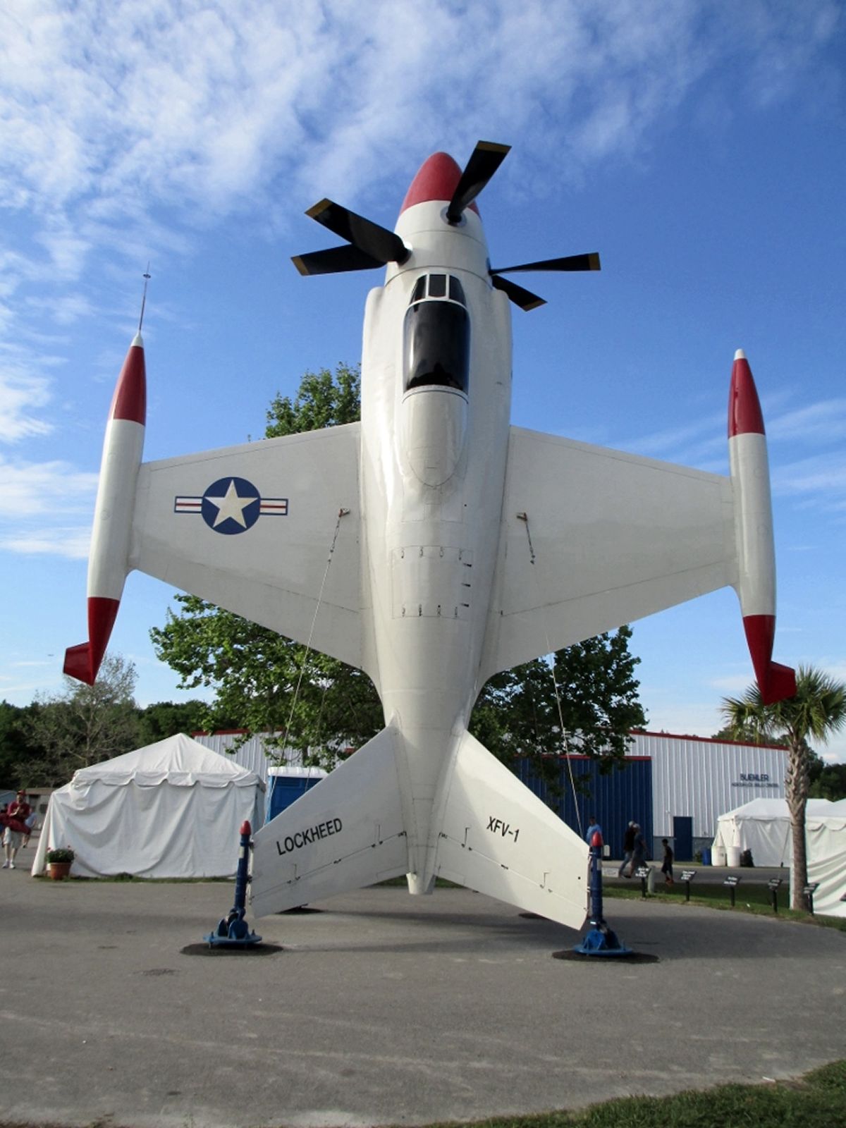
| Fig. 27. Drawing of the XFY-1 in hovering flight by Dan Witkoff, signed by pilot Skeets Coleman. Artwork is in the collection of the Rolls-Royce Heritage Trust Allison Branch, Indianapolis, Indiana, USA. | Fig. 28. Lockheed XFV-1 located at the Florida Air Museum, Lakeland, Florida, USA. Flight testing of the XFV-1 utilized a jury-rigged landing gear for standard horizontal takeoff and landing. While near-hovering flight of 80° was achieved during flight test, the XFV-1 never took off or landed vertically. | Fig. 29. Allison T40-A10 turboshaft engine in the collection of the Rolls-Royce Heritage Trust Allison Branch, Indianapolis, Indiana, USA. This particular version has the accessories on the top of the engine while the T40A-14 used in the XFY-1/XFV-2 had the accessories on the bottom for serviceability. |
 |
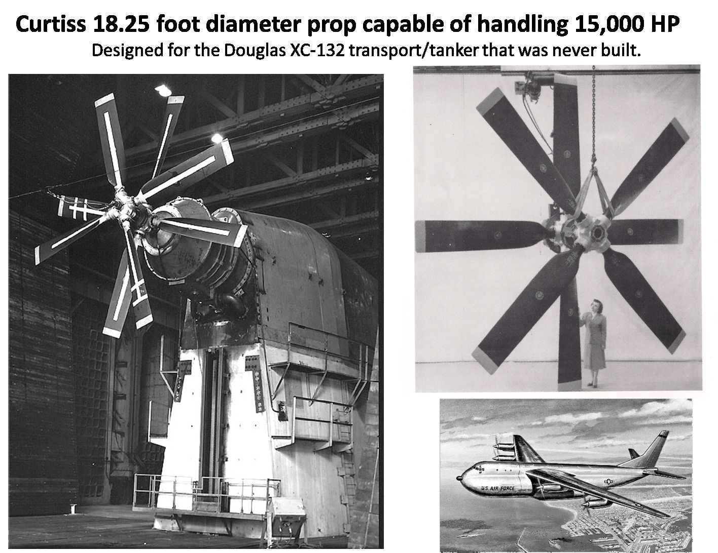 |
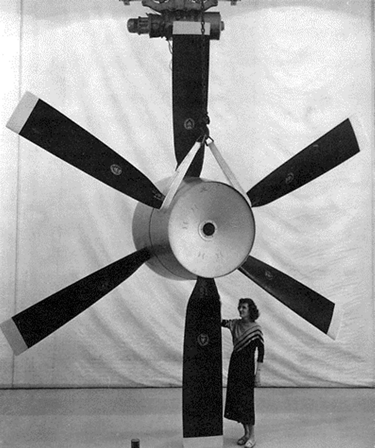
| Fig. 30. The Curtiss Turboelectric C(6L8)64S-A propeller used on the Convair XFY-1 and Lockheed XFV-1 was 16 ft in diameter. | Fig. 31. The proposed Douglas XC-132 heavy transport was to be powered by the Pratt & Whitney T57 turboshaft engine and either Hamilton Standard Model B48P6A single rotation propellers 20 ft in diameter or eight bladed Curtiss Turboelectric contra-rotating propellers 18 ft 3 inches in diameter. The aircraft was never built. |
Curtiss lost out to Aeroproducts and Hamilton Standard on supplying propellers for the Lockheed C-130 and the Lockheed L-188 Electra. Curtiss Electric’s final single rotation Turboelectric propeller was used on the fifty, four engine Douglas C-133 Cargomaster heavy transport aircraft that flew from 1956 to 1971. Curtiss soon faded away as a propeller company.
The Russians have persisted to the present time with their remarkable Tu-95 and An-22 aircraft using CRP units. And in the 1980’s, as well as the 2017 first run of the SAFRAN Open Rotor, there has been intermittent revival of dual rotation propeller sets, albeit they are technically and more rightly designated Propfans, Ultra High Bypass (UHB), Unducted Fans (UDF), or presently, Open Rotors. And that is topic for another time.
 |
 |
 |
 |
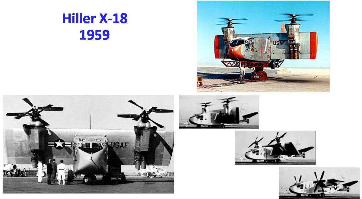 |
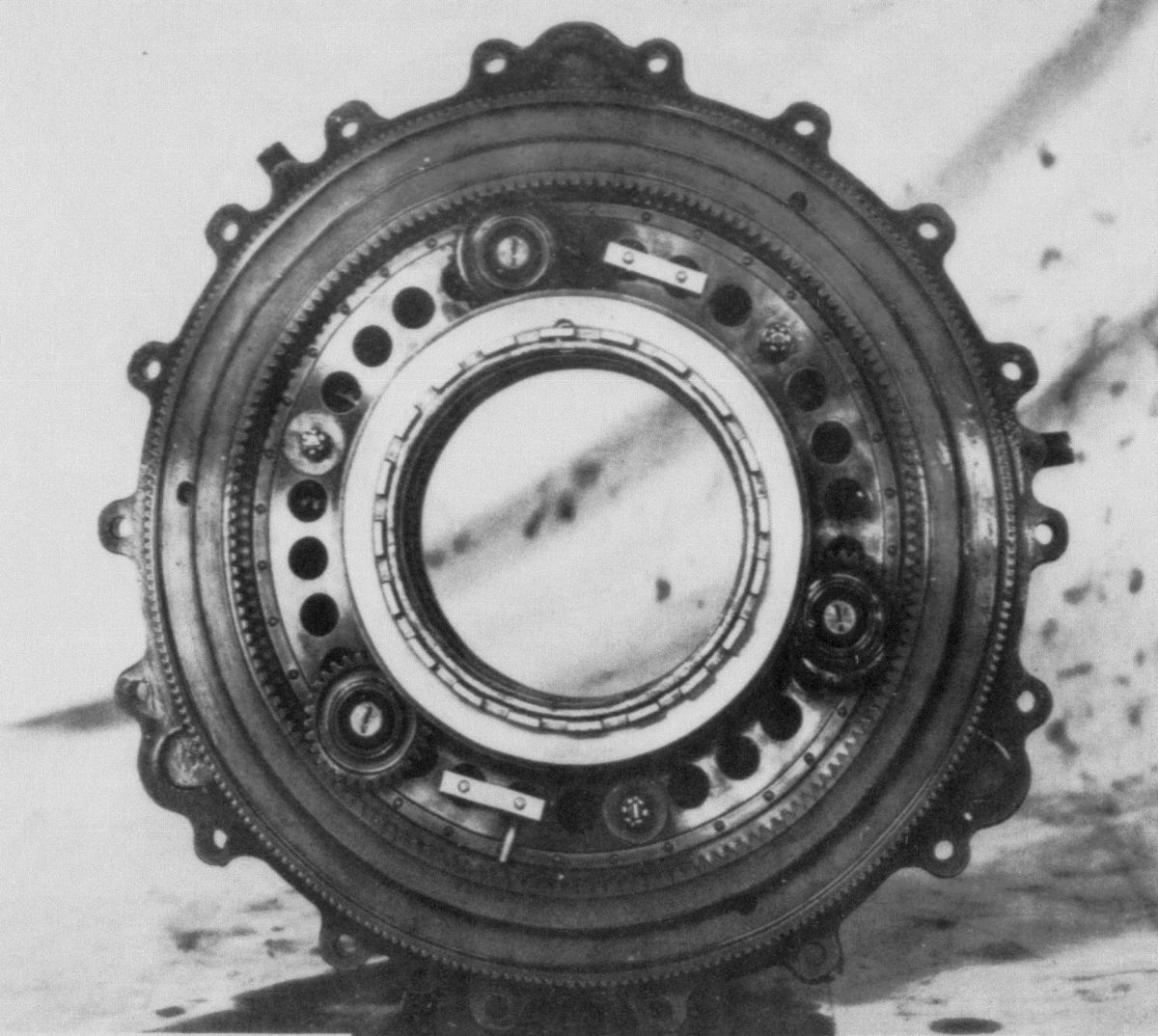
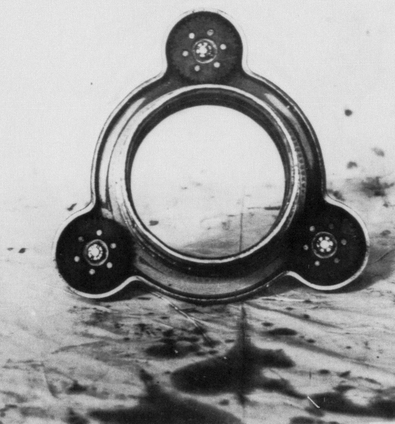
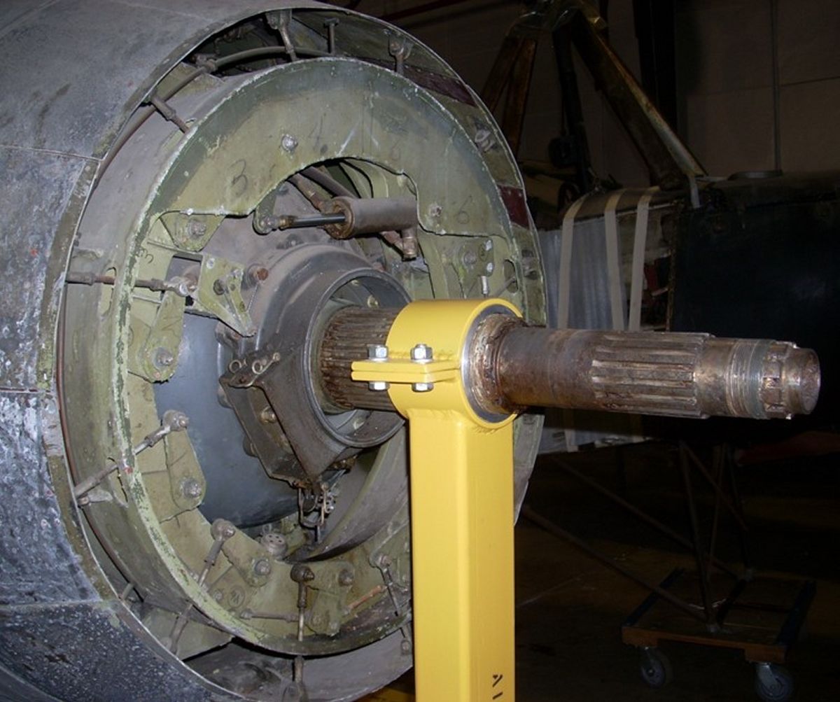
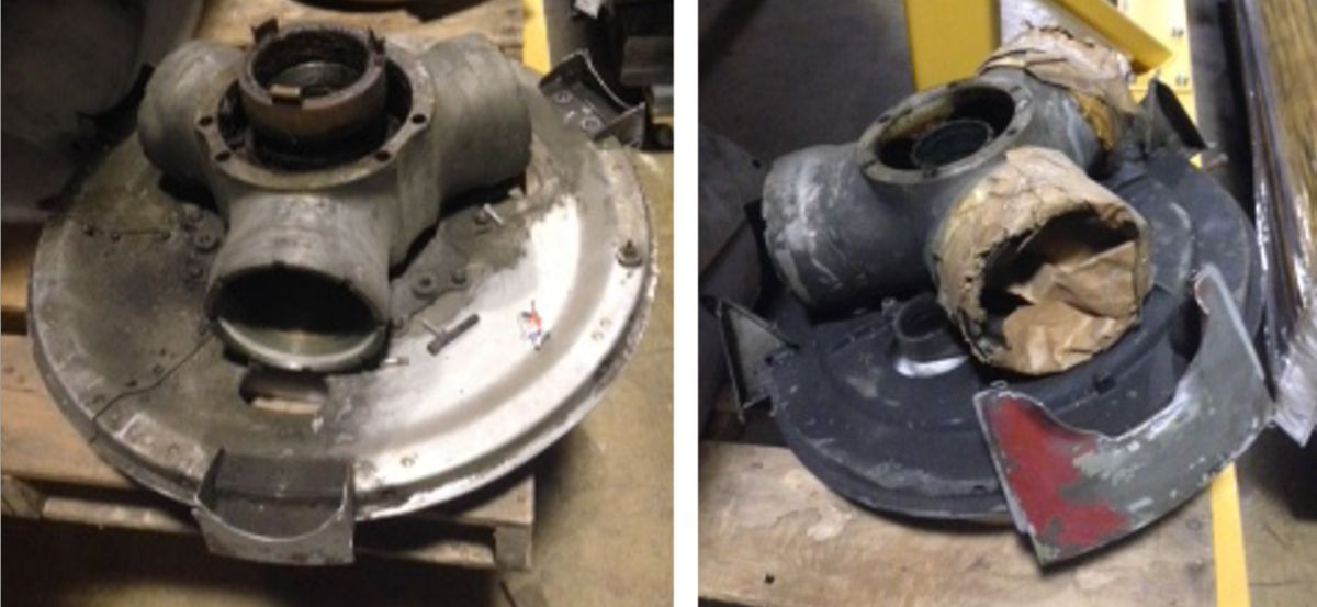
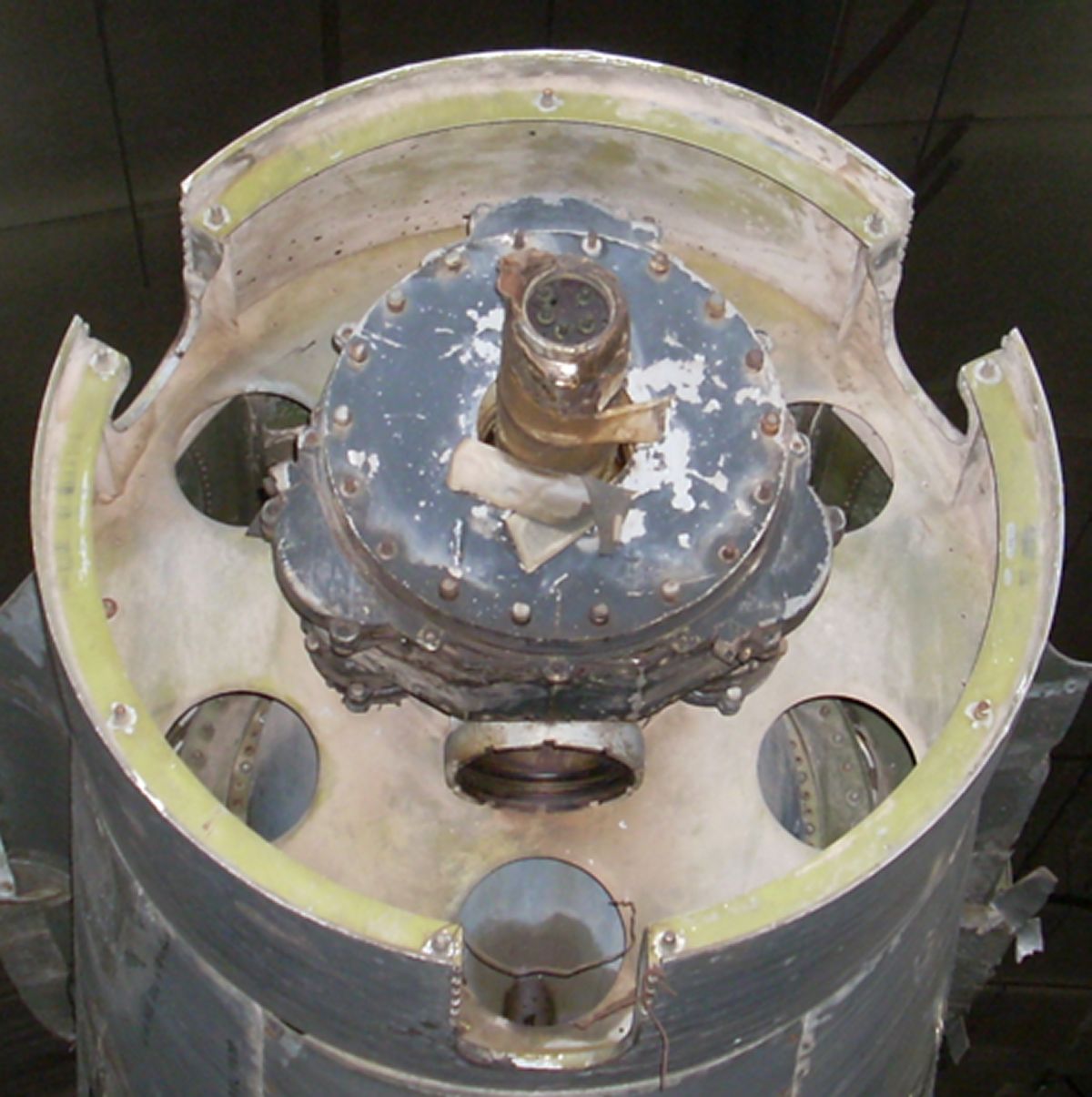
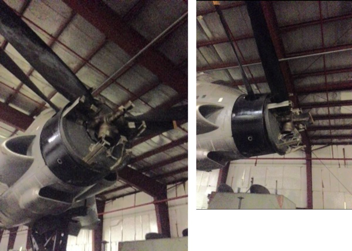
| Tail end of Northrop XP-56 showing the contra-rotating propeller shafts. Inboard shaft is 60 spline, which has 32 spline teeth. Outboard shaft is 40 spline with 16 teeth. Encircling the inboard prop shaft is the brush block retainer with the rectangular opening for the brush block at 8 o’clock. Cooling flaps and linkages with master actuator at 12 o’clock. NASM Garber Facility, May 2010. | Inboard (left) and outboard (right) prop hubs with spinner backplates for Curtiss Electric C(46)615SP-C1 from the XP-56. Note the holes in the backplate between the blade sockets in the outboard hub through which the flexible shafts run to the speed reducer. NASM Garber Facility, May 2016. | Rear view of the inboard component of the Curtiss Electric coaxial propeller on the Douglas XB-42A. The outboard propeller and components have been removed. Note the electrical posts in the bore of the outboard propeller shaft that controlled the electric pitch change mechanism in the outboard propeller. NASM Garber Facility, May 2010. | Partially disassembled outboard propeller on the Convair XFY-1. Aircraft is sitting horizontal on its dedicated tilting transporter. The 6 o’clock blade has been removed to remedy corrosion in the extruded hollow steel blade. NASM Garber Facility, May 2016. | The Hiller X-18 was an experimental vertical lift aircraft that utilized the Allison T40/Curtiss C(6L8)64S-A CRP propulsion systems from the cancelled XFY-1 and XFV-1 programs with a jet engine in the aft fuselage for maneuvering thrust. It never achieved vertical takeoff or hovering flight. |
References
Handbook of Operating and Maintenance Instructions Curtiss Hollow Shaft Electric Propeller, Technical Order Number T.O. 03-20BG-4, April 15, 1943.
Handbook of Instructions and Parts Catalog Hollow Shaft (Three Blade) Propeller Model C6315SH, AN 03-20BG-1, A.P. 2110A, 20 January 1944.
Type Test of Curtiss Dual Rotation Propeller Model C(57)615SP-A with Blades of Design Nos. 614-1C1.5-6 and 615-1C1.5-6, Army Air Forces Technical Report 5212, Whirl Test No. 1677, 26 March 1945.
Type Test of a Curtiss Dual Rotation Propeller Model Number C(57)615S-B with Curtiss Design Number 726-1C1.5-0 and 727-1C1.5-0 Blades for Use on an XP-62 Airplane Powered with an R-3350-17 Engine, Army Air Forces Technical Report 5377, Whirl Test No. 1689, 28 November 1945.
Type Test of a Curtiss Dual Rotation Propeller 9 Ft. 6 In. Diameter Model Number C(46)615SP-C1 with Blades of Design Nos. 512-4C1.5-18 and an Aircraftsman AC-104 Spinner, Army Air Forces Technical Report 5247, Whirl Test No. 1697, 26 July 1945.
Final Report on Inspection, Performance, and Acceptance of Curtiss-Wright XP-60A, C, and E Airplanes, Air Corps Technical Report 5286, 1945.
Final Report on Development, Procurement, and Acceptance of the XP-56 Airplane, Air Corps Technical Report 5714, 1948.
Curtiss Turboelectric and Turbo-Prop Engines Brochure, Copyright 1950, Curtiss-Wright Corporation Propeller Division.
Bladesman, publication of the Curtiss-Wright Corporation Propeller Division, November 1942.
The Design and Operation of Hollow-Shafted Constant Speed Propellers Part 2: The Curtiss Electric Propeller by Tom Fey. Torque Meter, Vol, 2, Number 2, Spring 2003.
US Patent 1,986,229 for a Controllable Pitch Propeller granted to Robert M. Stanley, 1 January 1935.
US Patent 2,533,346 for a Dual Rotation Propeller granted to George W. Bray and Charles W. Chillson, 12 January 1950.
XP-56 flight video: https://www.youtube.com/watch?v=MPMUnVeCBXw
XFY-1 Flight video with Skeets Coleman interview: https://www.youtube.com/watch?v=--0sYuheoPU
Send mail to
![]() with questions or comments about this web site.
with questions or comments about this web site.
![]()