
http://www.ctie.monash.edu.au/hargrave/rpav_radioplane3.html

where it meets the drive flange.
An Analysis of the Contra-Rotating Propellers
on the 1943 Radioplane OQ-2 Gunnery Target Drone
by Tom Fey
| The Radioplane OQ-2 (designated TDD-1 for the US Navy) gunnery target drone was a fascinating, radio-controlled, catapult launched, and parachute-recovered marvel that was privately developed in the late 1930s and entered military service in 1942. Three thousand eight hundred sixty five OQ-2s were built for the US Army, US Navy, and British allies during WWII. The pilot operated a joy stick which moved either the elevator or the rudder, only one surface in one direction at a time, while the unthrottled, 6 horsepower Righter 2-GS-17 engine ran wide open until disabled by gunfire or stopped by either the absence of a radio signal for 1 second, or the transmission of a “cut” radio signal, at which time the parachute was deployed. The aircraft weighed 108 pounds with 1.2 gallons of fuel and flew at 85 mph. Because of the simple airframe design and rudimentary radio control systems of the day, engine torque had a serious effect on handling, especially in the roll axis at low airspeed during launch. Thus engine designer Walter Righter incorporated contra-rotating propellers to eliminate engine torque. The 2-GS-17 engine was manufactured by Righter Manufacturing in Burbank, California as well as Herkimer Tool and Model Works in Herkimer, New York. The restoration of the 277 cc, 2 cylinder, 2-stroke, 27 pound Righter 2-GS-17 engine can be viewed by AEHS members in the Restoration section at http://www.enginehistory.org/members/index.php#Restoration, and an engine run on You Tube at: http://www.youtube.com/watch?v=HruyTW7c_4o. |
Contra-rotating propellers are an interesting subject, and the26-inch diameter props used on the 2-GS-17 offer a unique opportunity to examine the design of fixed-pitch, contra-rotating propellers at a time when contra-props were under development for full scale fighter aircraft. The interplay between blade sets due to forward airspeed, accelerated airflow from the fore prop onto the aft prop, and helical swirl from the fore blades onto the aft blades is a complicated dynamic, and designers can use airfoil shape, blade area, pitch magnitude and distribution, differing blade diameters, and in the case of co-axial props (props driven by two separate engines and independently controlled), different rotational speeds to optimize the efficiency and blade loadings of the two propellers. To add further complexity, the effect of Reynolds number (a non-dimensional factor that scales fluid flow under different conditions) means that the scale of the vehicle, in this case, target drones vs. full scale aircraft, also impacts propeller design.
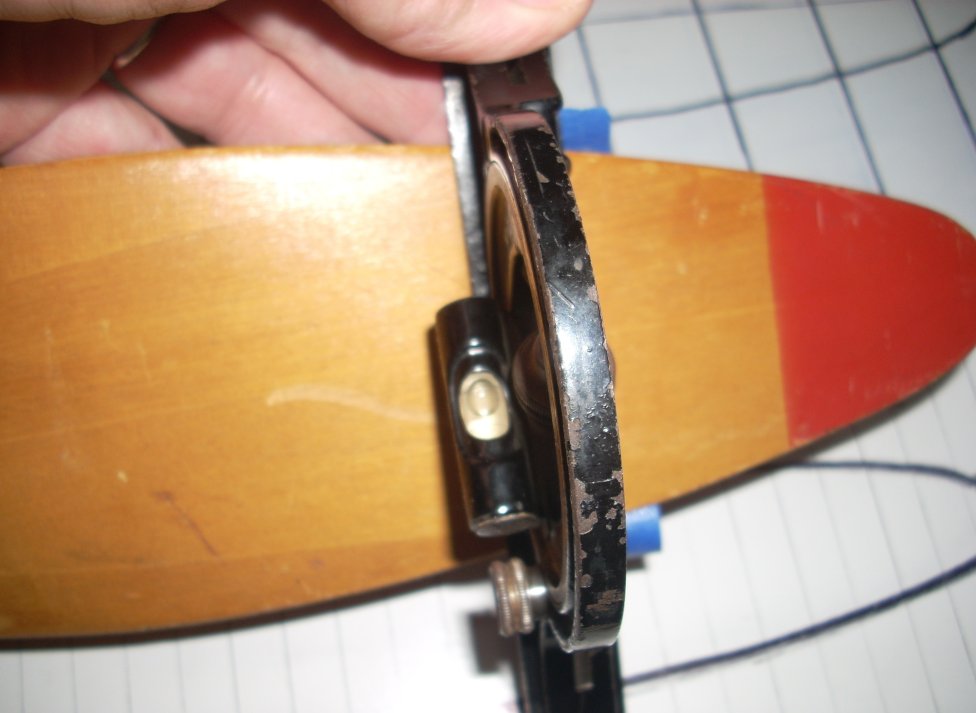
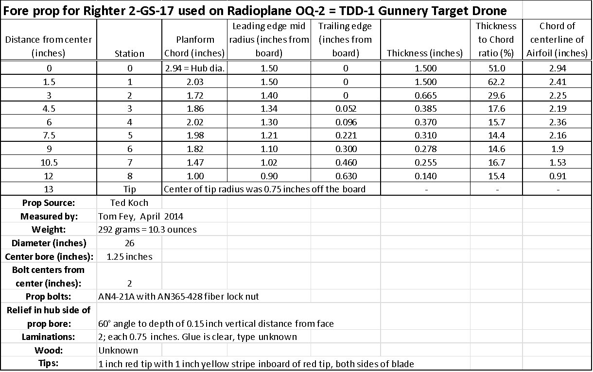
To get some insight into how an early, mass produced, and successful contra-prop blade set was designed, I was able to borrow a set of original OQ-2 propellers from AEHS member Ted Koch for measurement. Each propeller was bolted to a flat measuring board and stations were marked every 1.5 inches (11.5% increments) span wise from the center of the propeller (center = Station Zero). The vertical distance from the leading edge (LE) and trailing edge (TE) to the board surface was measured at each station, as well as the blade chord and “top view” planform of the prop. A profile gauge was used to make templates of the airfoil at each station for the camber (front) and thrust (aft) faces of the prop. On the thrust face, a bubble level accurate to 0.5° was modified with short pieces of brass rod to act as feet which touched only the TE and LE at each station, eliminating the difficulty of curved thrust surfaces and more accurate measurement of blade angle and thus pitch at various stations.
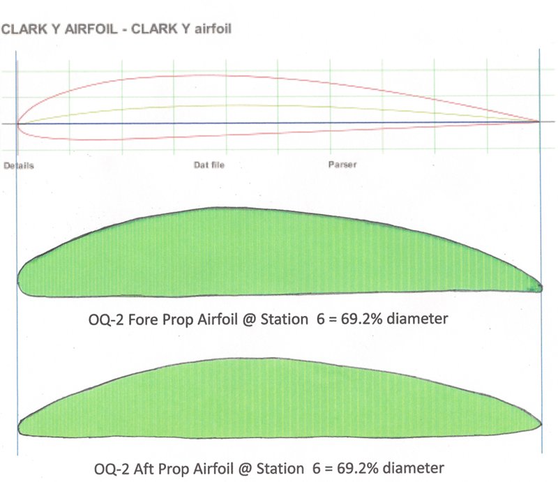
After making templates for the thrust and camber faces, I used “manual graphic methods” (photocopies, scissors, tape, and a document scanner) to overlap the templates and generate the airfoil shape for Station #6 (69% diameter) for both the fore and aft props. Propeller pitch is typically measured at the 75% diameter station. If I were a real aeronautical engineer I’d use a 3D scanner and computer systems to accurately digitize the information, but I’m an amateur fooling around in his basement.
|
|
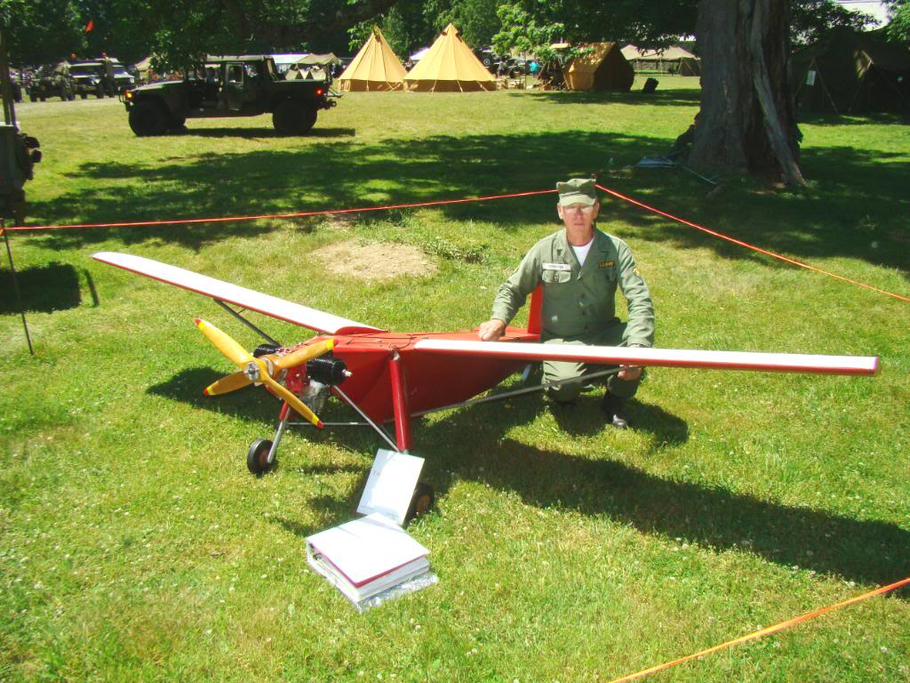
| The Radioplane OQ-2, fuselage without covering and the wing detached http://www.ctie.monash.edu.au/hargrave/rpav_radioplane3.html |
Beautifully restored OQ-2 on display at the Fort Bliss Museum, Texas |
|
|
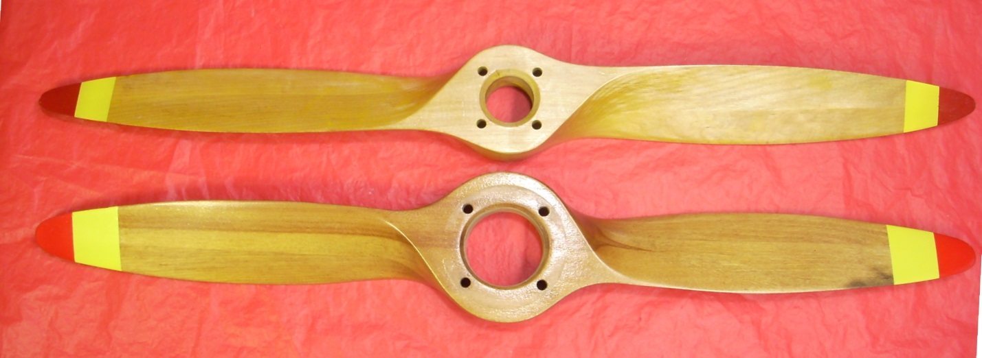
| Camber face. Center bore diameters are 1.25 inches fore prop (top) and 2.0 inches aft prop (bottom). | Thrust face. Note reliefs in the bore of each prop to accommodate the radius of the prop hub where it meets the drive flange. |
 |
 |
 |
| Two decals with slight variation from OQ-2 propellers made by Ritz Manufacturing Limited (left) and Ritz Engineering Company (right), Chicago, Illinois (Ted Koch) |
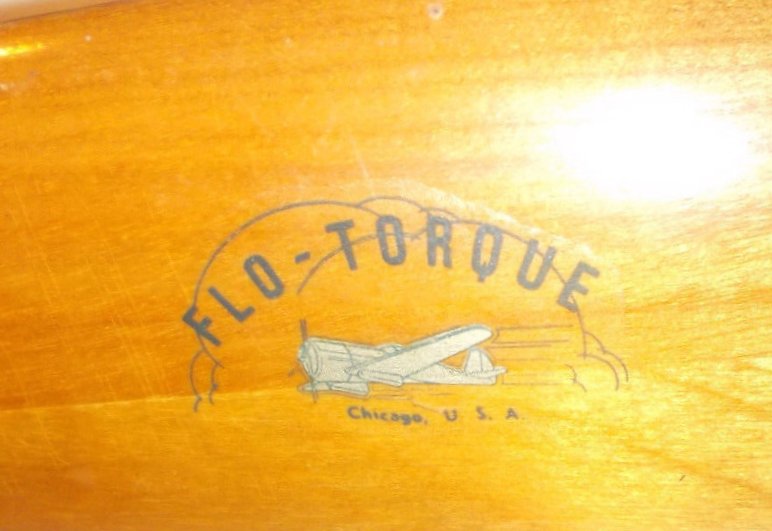
Decal from an OQ-2 propeller made by Flo-Torque, Chicago, Illinois | |
| Most original OQ-2 propellers are devoid of manufacturer marks or decals, however there are some propellers with decals indicating manufacture by Ritz and Flo-Torque, both located in Chicago, Illinois. | ||
 |
| Measuring the fore prop: TE measured using wire drill sized bits as feeler gauges shown for Station #5 on the right hand blade. |
 |
 |
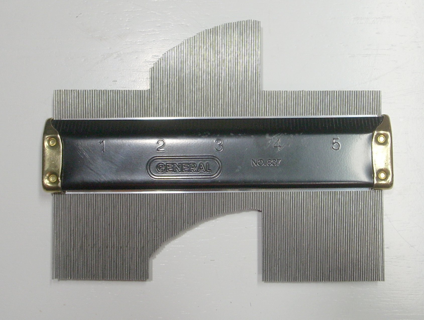 |
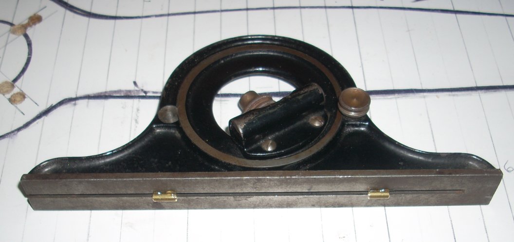
| Bubble protractor has rotating bezel with bubble level built into the opposite side. Brass feet allow measurement of non-flat thrust faces by just touching the TE and LE. | Measuring the angle of the thrust face of an OQ-14 propeller with a bubble level. Angle is read off the graduated bezel. | Profile gauge replicates profile of the airfoil, in this case Station #6, camber face of the aft prop. |
 |
| Templates on the camber face of the aft prop |
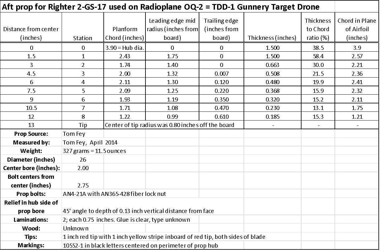
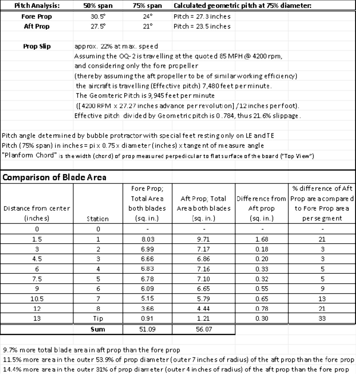
It is interesting to note that the pitch of the aft blade is a consistent 3° finer (lower pitch) than the fore propeller. This relative difference in pitch, which seems counter-intuitive, is common for many full scale contra-prop units such as Rotol and Aeroproducts, but not all of them. The reason for this difference is the helical flow off the fore propeller alters the angle of attack of the flow to the aft prop, thus “changes” the apparent pitch of the aft propeller. Depending on the scale of the propeller, prop loading, RPM, and airspeed, this difference in apparentpitch can be up to 15°. Thus the aft prop has a physically finer pitch than the fore prop, but has an apparent “working” pitch higher than the fore prop, and that optimizes the efficiency of the aft prop as it operates in the accelerated airflow from the fore prop.
As a rule of thumb, the outer 30% of the propeller diameter does 70% of the propulsive work. With this in mind, it is interesting to see the 13 to 33 % increase in blade area of the outer diameter of the aft blade compared to the fore blades. I cannot say exactly why this was done, or uncover the mathematics behind this complex phenomena, but it does go to show that the 1940s designers used all the tools at their disposal to maximize the efficiency and compatibility of the blades sets. Even for expendable gunnery target drones!
Just for fun I used the website: http://culverprops.com/CulverProps.html to calculate the desired prop pitch using the design parameters of the OQ-2: a 26 inch diameter propeller spinning at 4200 RPM flying at 85 mph. They recommended a pitch of 21 inches (no slip). Figuring in our calculated 22% slip, the recommended pitch goes to approx. 27 inches, which is the calculated geometric pitch of the OQ-2 fore propeller. I neglected the aft prop for this analysis by assuming it just added blade area to the fore prop.
Below in green are the (crude) airfoil sections from Station #6 for both the fore and aft OQ-2 props compared to the popular Clark-Y airfoil at the top. Leading edges are on the left and the sections oriented “flat” to enable easy visual comparison. Without precise measurements of the airfoil it is difficult to say exactly what airfoil section is used on the OQ-2 props, but this simple analysis tends to eliminate the Clark-Y from consideration.
Comparison of First and Current Generation R/C Aircraft Contra-Props
Since the 1942/1943 Radioplane OQ-2 was the first generation of radio-controlled (r/c) aircraft that utilized contra-props, it might be interesting to look at the current state of contra-props in r/c flying.
Contra-rotating coaxial propellers have become more common in the r/c aircraft hobby due to the power and flexibility of electric motors and controllers. Early r/c contra-prop efforts using a single motor and a gearbox to reverse the rotation of the aft prop were stymied mainly by the limited selection of opposite-handed props for use in the aft position. This greatly hindered the proper matching of the fore and aft propellers and often resulted in overloaded motors, stalled propellers, and thrust that varied significantly with airspeed. Interestingly, most modelers used aft props with pitches courser than the fore props. A further complication, which I have found difficult to quantify, is the effect of Reynolds number on the magnitude of helical flow due to the nature of the smaller diameter and more lightly blade-loaded r/c contra-props compared to full scale units.
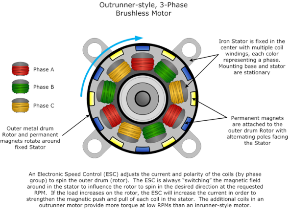
The advent of powerful brushless electric motors that can be digitally controlled to run either clockwise or counterclockwise has changed everything. The “outrunner” type of motor has the magnets epoxied into the motor casing while the stationary center stator has the windings that are switched on and off by the controller. The prop shaft is secured to the rotating motor casing. Because of the lever advantage of the larger diameter, the outrunner has greater torque than “inrunner” motors (which have the windings in the stationary casing while magnets are attached to the spinning central rotor). Outrunners are easily adapted to a coaxial configuration using two configurations of the basic outrunner motor. In the first variation, which is typically the aft motor, the central prop shaft is an extension of the spinning motor case (configured similar to a bell gear) which extends through the hollow rotor of the fore motor and drives the fore prop. A second configuration is used for the fore motor that drives the aft prop. In this situation, the shaft and rotor are fixed while the motor casing rotates around the rotor. The aft prop is then bolted to the motor case. The dual motor assembly is attached to the airplane structure by a mount situated between the motors.
Each motor has its own controller, thus these systems are actually dual rotation, coaxial propeller installations. The ability to independently vary motor speed between the prop sets coupled with ground use or even airborne electronic systems to measure RPM, volts, and amperage on each motor provides data for the builder to tailor pitch, diameter, and loading between the blade sets for best performance. The selection of opposite-turning aft props is still somewhat limited, but the ability to adjust the diameter and particularly the RPM independently allows reasonable matches to be made with the fore prop.
 |
 |
| Diagram from: http://2bfly.com/knowledgebase/powerplants/brushless-dc-motors/outrunners/ | Coaxial, dual rotation brushless electric motor unit. The rotating components are the rear bell casing (with long extension prop shaft) with the “Himax” label (drives fore prop) and the blue motor casing that has the nut on it. The stators for both motors are held stationary by the 4-point mount. Diagram from: http://www.maxxprod.com/mpi/mpi-266.html |
The performance of the r/c coaxial units are impressive, but careful integration into the airframe and trimming of the aircraft are essential. Contra-prop and coaxial units also tend to be louder than single-rotation propellers.
http://amaflightschool.org/video/keith-shaws-bugatti-racer
http://www.youtube.com/watch?feature=player_embedded&v=R9Wq4ZdQrtg
http://www.youtube.com/watch?v=md_99-WGSEA
http://www.youtube.com/watch?v=FTLLZcVC0Uk
The Bugatti 100P by Keith Shaw (circa 2004) used two inrunner brushless motors on a special gearbox with a reduction of 2.5 to 1 for the fore prop (11 inch diameter x 8 inch pitch) and 3 to 1 for the 11 x 11 prop in the aft position. The M.B.5 and Mark Rittinger’s P-51 air racer Precious Metal use the tandem outrunner motor set up. Rittinger’s P-51 uses a 12 x 8 prop in the fore position and 12 x 8.5 (cut to 11.5 in diameter) which gives an equivalent current draw by both motors under static conditions.
It is difficult to sort out a priori the 3 dimensional chess of diameter, pitch, and RPM of dual rotation propellers, but it seems these model aircraft perform best with the aft props of similar or slightly higher pitch than the fore prop. Based on the analysis of the OQ-2 props which are similar to the full-size aircraft having aft props indexed with finer pitches than the fore prop, r/c models tend to be different. And this is now something I look forward to investigating.
Tom Fey
Arlington Heights, IL
May 12, 2014
Send mail to
![]() with questions or comments about this web site.
with questions or comments about this web site.
![]()