
(Kimble D. McCutcheon)
(Kimble D. McCutcheon)
The Rolls-Royce Merlin Aero Engine
Early Development 1933 - 1937: The Ramp Head Merlin
by J. SJ. Wells
Trentham, Victoria, Australia
| The first part of this article, "The Genesis of the Merlin", was published in Torque Meter Vol. 5, No. 2 in the Spring of 2006. The "Postscriptum" appeared in early 2008, and was intended to extend the earlier material, as well as to introduce a second engine. This version is the 4th Edition, which was released in February 2010. |
|
|
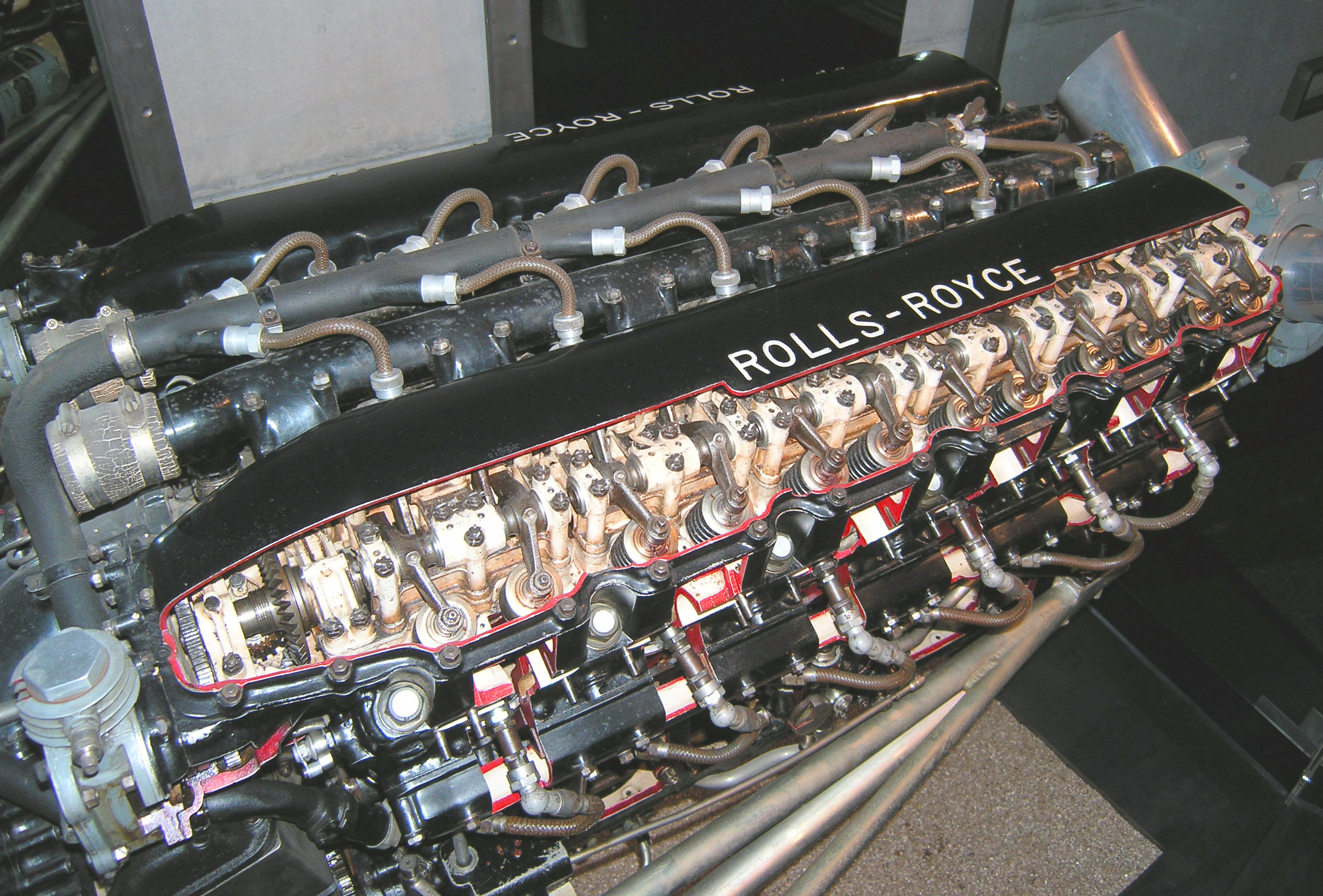
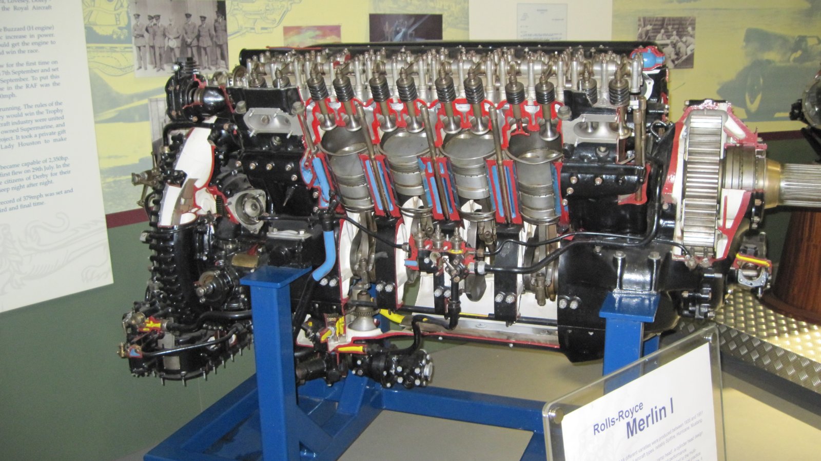
| Rolls-Royce Heritage Trust Merlin Mk 1 at Derby (Kimble D. McCutcheon) |
Rolls-Royce Heritage Trust Merlin Mk 1 at Derby (Kimble D. McCutcheon) |
The Genesis of the Merlin
In 1932, Frederick Henry Royce (F.H.R.), knight of the realm and autocratic head of Rolls-Royce Ltd, decided the time was apposite to design a new, high-power, military aero-engine.
At that point in time, F.H.R., then aged 69, must have been feeling pleased with himself given that, in recent times, a number of air and water speed records had been broken by machines powered with his company’s engines.
As far as a new engine was concerned, Royce had a number of options available to him, including:
1) development of the Kestrel,
2) development of the Buzzard,
3) detuning of the "R".
In the case of the Kestrel, there were deep-rooted problems which stemmed from the very beginning of the engine’s life. The creation of the first monoblock aero-engines of Rolls-Royce had been prompted by the appearance of the Curtiss D-12 in 1921. R-R were sent a complete example of the D-12 in 1924 (it was actually Eng. No. 252, the very last of the B-models) by the Air Ministry who suggested that F.H.R. and his team use it for "inspiration."
Displaying, it would seem, a certain amount of arrogance, R-R collectively dismissed the use of wet liners (which were such an innovative feature of the D-12) and set about designing and building a dry-liner V-12. In no time at all they found themselves up to their necks with problems of overheating and piston seizure, which they solved by switching to a wet liner design. But the damage had been done because in the dry liner scheme, the cylinder blocks were secured to the crankcase by four rows of seven bolts, i.e., effectively, four bolts per cylinder which was fine as long as the blocks bedded directly onto the crankcase thus giving plenty of stability. In the wet liner design, only the liners connected the blocks to the crankcase. Four bolts per cylinder were insufficient and in Rubbra’s words, "Undoubtedly, the worst trouble experienced on the Kestrel in service was leaking cylinder head joints. These would sometimes lead to a cylinder becoming partially filled with water on standing resulting in a failed con-rod when starting up."[1]
As a basis for a new engine, the Buzzard would have been a much better choice. From Kestrel experience, R-R had learned that each cylinder needed six cylinder head studs. This move terminated the leaking of the top joints in both the Buzzard and the highly modified "R."
As it happened, Royce and his team chose to use the experience they had gained from previous engines rather than a specific model to develop a new V-12 powerplant. The PV-12 was to have two features which would distinguish it from previous designs. First, to ensure there would be no repetition of the internal coolant leaks, separate cylinder heads would be used so that a close eye could be kept on the liner top joint. According to Rudd[2], one of Royce’s instructions to his apprentices was, "If you can’t inspect it, don’t build it." Second, to ensure maximum structural strength, the engine was to be a true monoblock design, i.e., the cylinder barrels would be completely unstressed as in the Curtiss D-12. The heads, cylinder blocks and crankcase would be assembled in close contact with each other thus giving mutual support. A third, minor difference, was that the capacity would be between that of the Kestrel and the Buzzard.
Thus the PV-12 was born — its construction consisted of three major components; the upper crankcase plus the cylinder blocks and the two cylinder heads. This kind of constrction is the simplest and strongest way of making a V-shaped engine. Millions of V-6 and V-8 aout engines attest to that.
All other components including crankshaft, pistons, and valve mechanism were carried over from the Kestrel/Buzzard. Inverted layout, evaporative cooling and herringbone reduction gears were toyed with but quickly discarded. Two PV-12s were built with factory numbers were 1 and 3 (odd numbers only for right-hand tractor engines) and, initially, the construction was funded by by Rolls-Royce Ltd. Paradoxically, of the 160,000 Merlin engines that were subsequently manufactured, only the first two were actually made as the Great Man intended. Later the government paid for the engines and the usual "A" numbers were allocated, in this case, A111,145 and A111,141.
However, much more significantly, while the two PV-12s were being built, Sir Henry Royce died (22 April 1933) and with the demise of the chief project engineer, the Merlin took a downward dive from which it never really recovered until the first separate cylinder head Merlin 28/29s began coming off the production line at the Packard motor Co. in Detroit, U.S.A. in 1941.
The Origin of the "Ramp Head"
Owing to poor health, Henry Royce spent the latter half of his life domiciled on the South coast of England, which is nearly 200 miles from the factory in Derby. To help him with his deliberations and to facilitate liaison with the main works, an engineer named Albert George Elliott was hired. By all accounts an affable fellow, Elliott got on well with F.H.R. even though he was 25 years his junior.
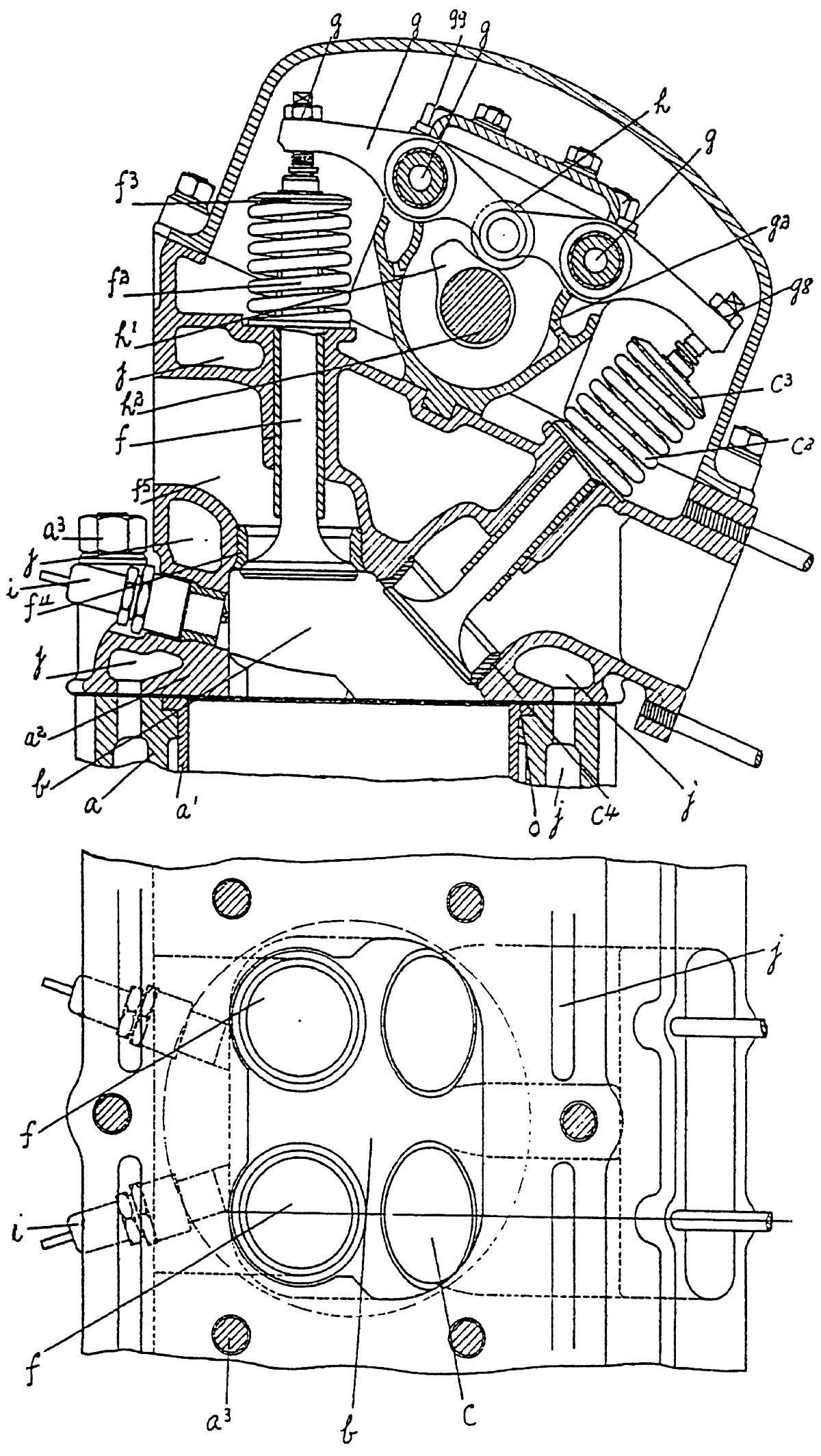
It is clear from documents penned by Elliott in the mid-1920s that this engineer held some very firm ideas as to how good combustion could be achieved in internal combustion engines. Elliott felt that the key to avoiding detonation and ensuring clean burning was turbulence of the mixture — not just turbulence due to the gases rushing past the inlet valves but extreme and violent swirling generated by the piston moving the mixture into the combustion chamber during the compression stroke. To make this happen, Elliott postulated the use of cube-shaped combustion chambers (Figs. 1 ~ 12). The sides of these chambers, when assembled on top of the cylinders formed horizontal barrier walls that the mixture had to flow around during the upward movement of the piston to, "produce violent cross-currents in the mixture" and "cause cross-currents and, ultimately a great turbulence in the explosion chamber at the moment of maximum compression."[3] Elliott was also concerned that people might confuse his invention theory with what was commonly known as "squish", i.e., where the combustion chamber was designed to incorporate corners or wedges into which the mixture could be progressively funnelled during the compression stroke. To make this distinction clear he said, "I am also aware that it has been proposed to construct a wedge shaped explosion chamber, the thin end of the wedge only being over the piston, but such an explosion chamber would not produce turbulence as efficiently as the inwardly projecting parts of the explosion chambers constructed according to this invention."
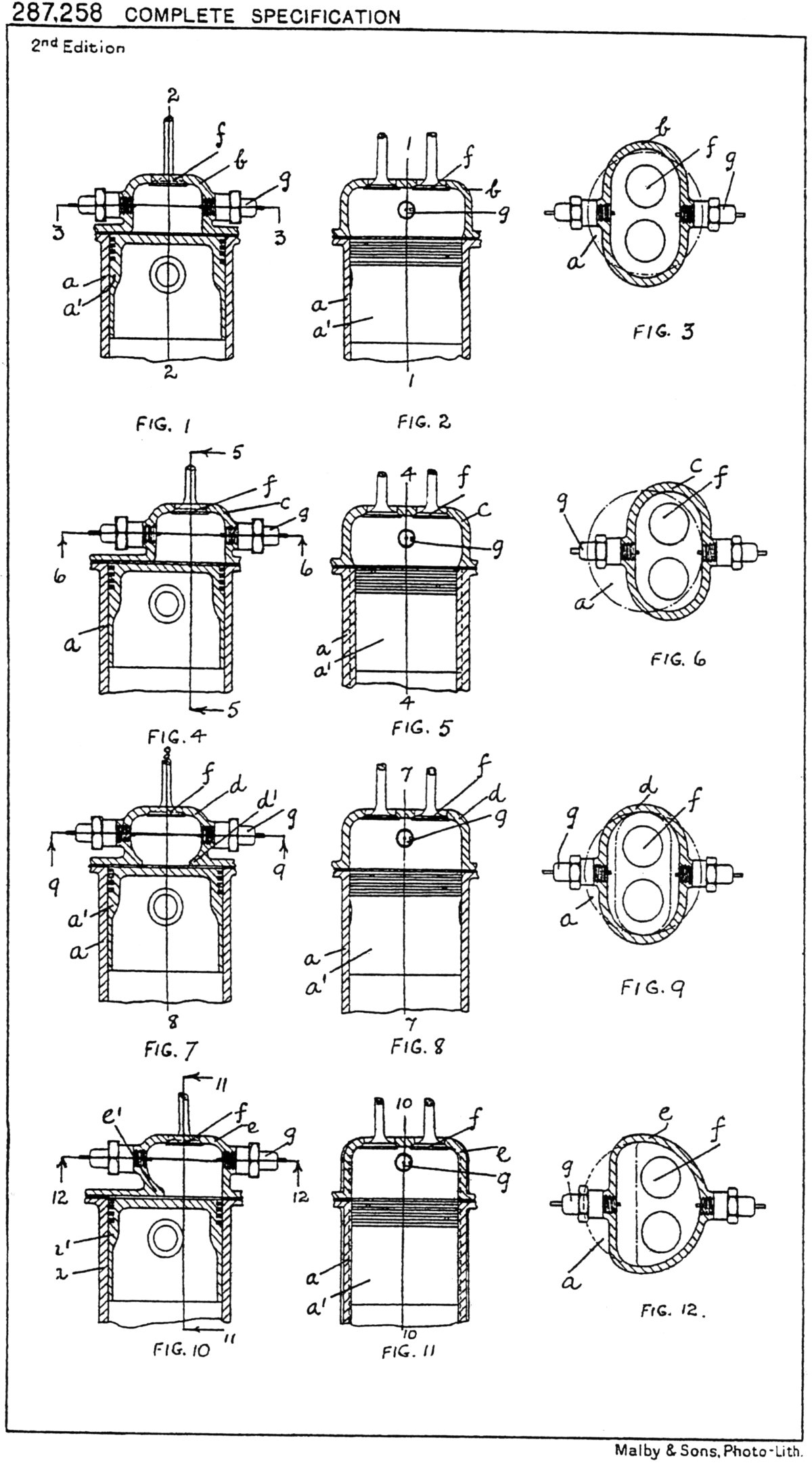 |
| Figs. 1~12. Four variations of Elliott’s cube-on-a-cylinder combustion chamber. Note that in one plane (Figs. 2, 5, 8, 11) the combustion chamber is very conventional in shape. At right angles to this, one or both sides of the chamber are squeezed in to produce shelves around which the gas must flow. |
Elliott patented his ideas in 1927 and must have discussed them at length with Henry Royce. Whatever Royce thought of the theories there is not the slightest indication that he intended to apply them to the PV-12 — the two prototypes were built with conventional, flat Kestrel-type cylinder heads.
Shortly before Royce’s death in 1933, Elliott was transferred from the coast to Derby and given the influential post of Chief Engineer. The demise of Royce presented Elliott with a golden opportunity to apply his ideas on cylinder head construction and thus stamp his mark on Rolls-Royce engines. It would seem that he wasted no time in espousing his theories to his fellow Derby engineers because even before the end of 1933, fellow R-R engineer James Denning Pearson had filed a patent "primarily for application to an engine with combustion chambers arranged as described in Letter Patent No 287,258." (i.e., Elliott’s 1927 specification).
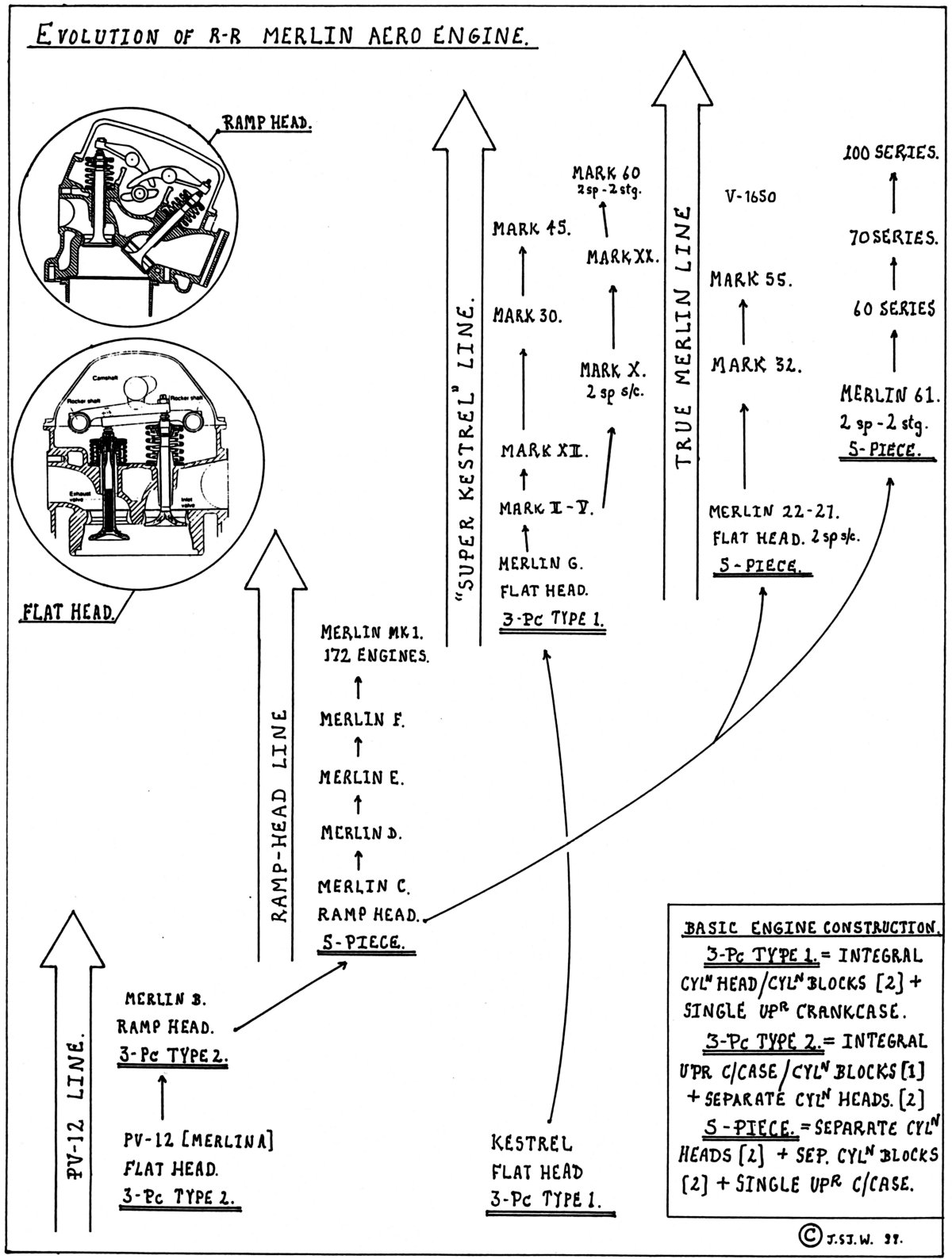 |
| Fig. 13. Four Main Merlin Development Lines According to Basic Construction. Note there is no arrow linking the Kestrel to the PV-12 — in the Kestrel the liners were an integral part of the engine structure; not so in the PV-12. Similarly, there is no linkage between the Merlin F and the Merlin G. |
Pearson’s design is illustrated in Figure 14. Clearly, it is the push-rod version of the ramp head in two-valve form, probably intended for a road vehicle. Pearson justifies the canting of the inlet valves from the vertical to the 45° position as follows, "In the arrangement described in the said Letters Patent (Elliott’s 1927 document), difficulties may be experienced owing to the proximity of the walls of the combustion chamber to the valves and particularly to the inlet valve which may cause interference with the "breathing" of the engine. This invention has for its primary object to avoid such interference. The inlet valve is set at an angle of 45 degrees, the side of the combustion chamber which forms the valve seating being also set at such an angle."[4] And so, through Pearson’s modification of Elliott’s original concept, the infamous ramp head came into being.
Most accounts in the aero-engine literature claim that the term "ramp-head" derives from the shape of the combustion chamber as seen in a sectional drawing of the cylinder head, but it is also possible that "ramp" refers to the presence and operation of the inwardly directed projections, which were, of course, the crux of the Elliott invention.
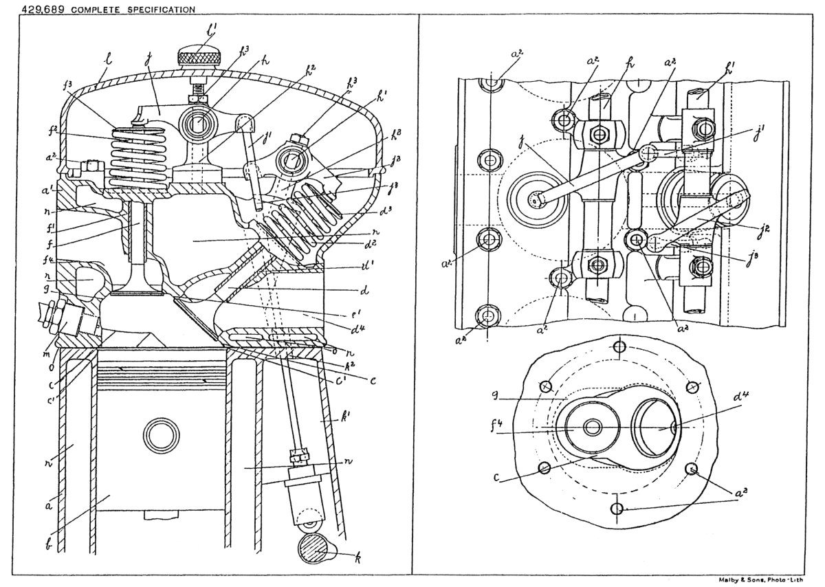 |
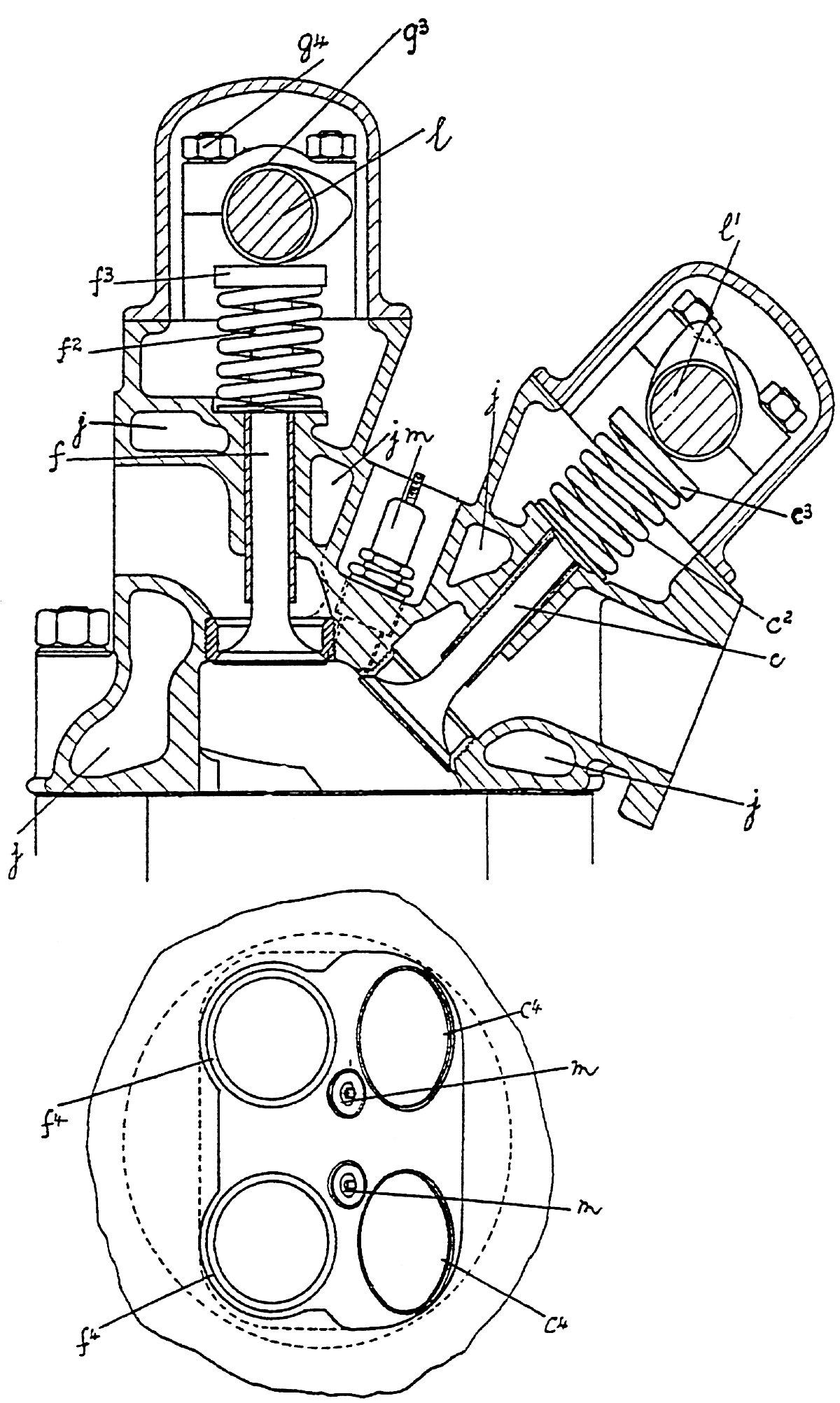
| Fig. 14. Three Views of the 2-Valve, Pushrod Version of the Ramp Head. Note the valve covers are secured by knurled nuts. This method was trialed on the prototype Griffon engines. |
An Extraordinary Decision
An indication of Elliott’s determination to apply the ramp-head to all Rolls-Royce engines is given by noting that less than a month, after Pearson’s application for a two-valve ramp-head design, Elliott and Pearson filed a patent for a four-valve per cylinder version (Fig 15).[5] This occurred on 2 January 1934, six months before Rolls-Royce managed to get a PV-12 through a less than impressive type test.
Sometime in the latter half of 1933, Elliott informed the PV-12 development team of his decision to change the engine’s cylinder heads to the ramp type. This announcement would have been greeted with astonishment, amazement and probably, dismay by the engineers involved. They already had major problems to contend with and the introduction of an untried, untested modification to a brand new engine had the potential to add significantly to their woes. The logical step to take in this situation would have been to carry out a parallel course of development using at least one engine with standard-type cylinder heads. Perhaps it was an indication of Elliott;s obsession with the ramp-head design that this did not occur.
The flat-head combustion chamber/valve arrangement had been tried proven by way of 4,700 Kestrels, 100 Buzzards and 20 highly stressed "R" engines. It was sturdy, reliable, easy to maintain, inspect and service. In a new engine it was one of the known quantities and to change it during the early stages of the Merlin’s development was an invitation to disaster.
However, Elliott got his way and two Merlins with ramp heads were built in 1934. They were designated Merlin B and the Air Ministry numbers given to them were A111,137 and A111,138. The first run of a Merlin B was February 27, 1935. The ramp heads proved to be extremely troublesome as Rubbra points out,
1. The power output was inferior to the flat-head design.
2. The detonation characteristics were worse than with normal heads.
3. There was burning of the exhaust port walls.
4. There was wear and break-up of the rocker arm pads.[1]
So, however many problems the PV-12 (retrospectively named Merlin A) had, it would be fair to say the number had been significantly increased by the presence of the ramp heads.
 |
 |
| Fig. 15. Two views show the Goshawk B version of the ramp head with both spark plugs on the exhaust side of the combustion chamber. Note that each cylinder is secured by six bolts as in the Buzzard. | Fig. 16. Alternative ramp head design with two overhead camshafts and central location of the spark plugs. |
Single-Cylinder Testing
For manufacturers of large complex engines, component testing was an obvious cost-saving strategy to employ. At R-R, experimentation and engine testing was part of the company from the time it started. In any book on R-R motor cars, there are usually as many photos of prototypes on test as there are of production vehicles! Ernest Hives (at the age of 30) was made head of the Experimental Dept. in 1916. (By 1937, after his appointment to the post of General Works Manager, he described the Experimental Department as, "too big and too expensive!")
Chris Harrison[9], a long-serving R-R engine tester says, "It is relevant to mention that an enormous amount of development was carried out on various components before they ever reached engine status. For instance, the Single-Cylinder Beds were used to trial con-rods, pistons, bearings, valves, cams and liners, etc., and superchargers were developed and calibrated on their own test rigs."
Ronnie Harker[10], an equally long-serving R-R employee says, "My first task (in 1931) was to help Bob Young in running a single-cylinder unit on the test bed. The cylinder was the same size as one of the 'R' engine ones but it was much cheaper to develop the cylinder this way than running a complete engine. The object was to extract as much power as possible from the cylinder by improving valve cooling, spark plugs, ignition timing and so on. We developed it to give 200 BHP and it made a most frightful din!"
With regard to the ramp-head single-cylinder testing, Rubbra states, "When cylinder blocks of this type were tried on the Merlin, it was found that the increase in power relative to the boost pressure obtained on the single-cylinder unit was not achieved on the main engine and although considerable investigation was put in hand to find out why this should be so, the point was never solved ...etc."
Now this takes the discussion fairly and squarely into the realms of incredulity because the notion that none of the problems listed above had become evident during the single-cylinder testing is absurd. Extensive normal running and more importantly, over-load testing would have certainly revealed the subsequent whole-engine problems.
A more likely explanation is that the unsatisfactory results were obtained but they were rationalized or even dismissed by Elliott (to whom such results would have come directly) whose faith in his invention was so blind that he was sure the problems could have been solved with a bit of development on complete 12-cylinder engines. Clearly, he was operating on the principle often followed in the performing arts arena, "It'll be all right on the night." There was a lot a stake here for Elliott at this point in time. As pointed out above, one of his first decisions as Chief Engineer was to substitute (not supplement) his ramp-head design for the usual arrangement. Ergo, he had no "fall-back" plan or position.
The Long Road Back
One of the major problems with the PV-12 was cracking of the cylinder jackets. This is hard to understand because all through the aero-engine literature, mention of Rolls-Royce expertise with metal alloys invariably occurs. Accounts of Royce’s particular interest in the subject; of the establishment of a company research unit as early as 1916; of the 65 patents taken out for R-R alloys; of the importance of new alloys in keeping the "R" competition engines in one piece abound.
Perhaps, therefore, Royce was asking too much of his engineers and metallurgists. Was the PV-12 design ahead of its time? Not a bit of it! One only has to look at the situation in Germany in the early 1930s where Daimler-Benz and Junkers were also preparing to manufacture high-powered, liquid-cooled, mono-block engines. At Junkers, the Ju 210/211 engines were, constructionally, astonishingly similar to the R-R PV-12 — same one-piece upper crankcase/cylinder block casting; same separate cylinder heads; same unstressed wet liners, etc. Even the valve gear with its single overhead camshaft (per bank) acting on cross-over lever tappets was identical to the R-R mechanism. In the context of this article, the Ju 211 engine could fairly be described as the "German PV-12". The point being that Junkers managed to manufacture 68,000 "PV-12s" in total thus proving that the technology of the day was up to the task.
The proposed remedy to the cracking was to separate the cylinder blocks from the crankcase and so the two PV-12s and the two Merlin Bs had the cylinder blocks unceremoniously sliced off the crankcases. Appropriate threaded holes were then drilled into the decapitated crankcases and new cylinder blocks were bolted on. This seemed to have help the cracking but in contrast, there were no solutions to the ramp-head problems.
Rubbra claims, "In order to obtain more experience of this type of head, it was decided to design a version to suit the Goshawk engine known as the Goshawk B and considerable satisfactory running experience was quickly obtained on an engine so converted."[1] In a photo of this engine[1], it can be clearly seen that both spark plugs for each cylinder are on the same (exhaust) side (see also Fig. 15). Elliott comments, "By placing the sparking plugs in the position shown in Figure 15, the last gas to burn will be in the coolest part of the head, i.e., that furthest away from the exhaust ports and the combustion chamber is so shaped that the section tapers away towards the end of the travel of the front of the flame which tends to suppress detonation."[5]
This puts Elliott at cross purposes with himself because the whole point of his cube-on-a-cylinder design was to generate "violent cross currents and great turbulence in the explosion chamber." If his theories were correct the position of the spark plugs should be irrelevant because the "great turbulence" would practically eliminate an even flame front.
As the sorry saga of the ramp head dragged on, Elliott and Pearson realized they had made a dreadful error and to try and rectify matters they filed another patent in August 1935 in which they acknowledged that the ramp head design, rather than decrease the possibility of detonation, was likely to promote its occurrence. In their words, "With the ignition plugs located as described in the previous specification, the mixture in this corner will be the last to be ignited and may, under certain conditions, cause detonation in the combustion chamber. According to this invention therefore an, ignition plug is located between the inlet valves."[6] Essentially, this is a polite and diplomatic way of saying that the ramp head, in both theory and practice, didn't work. It also contradicts Rubbra's glowing assessment of the Goshawk B whose cylinder head was characterized by having all the spark plugs on the outside of the cylinder banks, much like the Mercedes DB 600 engines.
A couple of the earlier prototype engines (probably C models) were fitted with redesigned cylinder heads that had the spark plugs located conventionally and such was the magnitude of the change that they were identified as Merlin Es.
The final production arrangement is shown in Figure 17 with the inlet side spark plug located at the bottom of a long tube. Getting it in and out of the head must have been very difficult as would keeping it cool when the engine was operating.
The new spark plug arrangement didn’t help much and at this point the Merlin project virtually ground to a halt. All through 1935, C-models were tested without much success. In June, Engine No. 5 was sent to Supermarine’s at Eastleigh for installation checks in the prototype Spitfire and, similarly, No 7 to Hawker’s at Kingston for the prototype Hurricane. The Air ministry, quite understandably, were not particularly happy about having expensive prototype aircraft powered by suspect engines.
The ramp head Merlins went through D-stage, E-stage and F-stage programmes all aimed at getting the engine to pass the standard 100-hour military qualification test but no ramp head Merlin ever achieved this.
With war clouds gathering, it would be an understatement to say that a fair degree of panic set in at both the British Air Ministry and at Rolls-Royce headquarters. The Air ministry, under this pressure, made what might be called a "Dragonfly decision", i.e., they ordered an unqualified engine into production. Most of the 170 Merlins that were manufactured ended up at Fairey Co. for installation in "Battle" aircraft.
 |
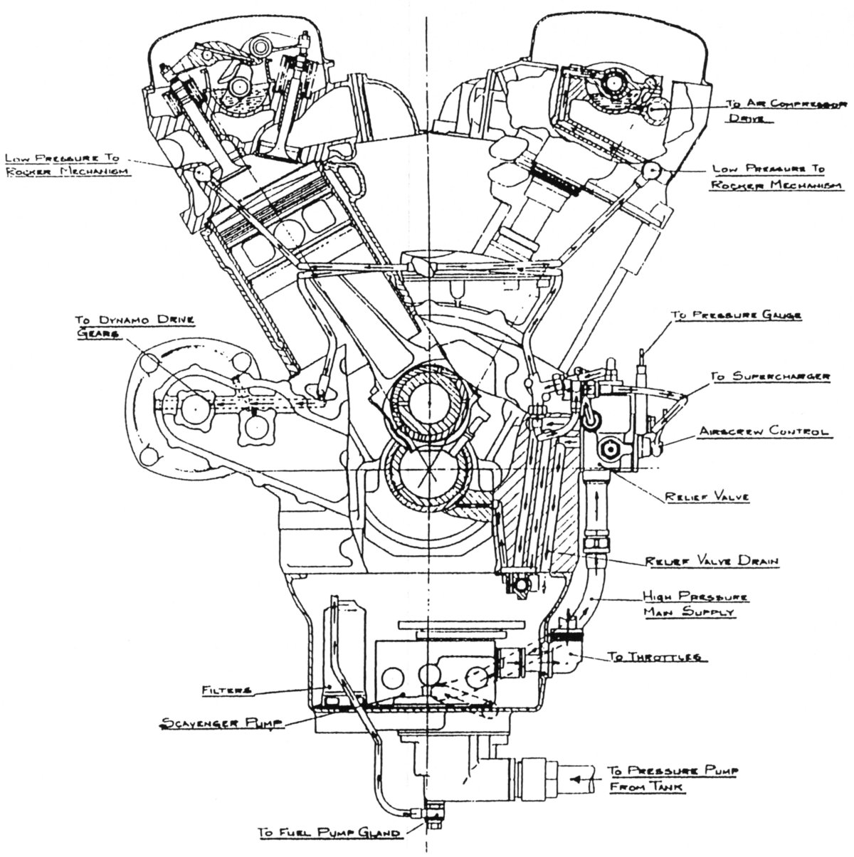 |
| Fig. 17. Production version of the ramp head with opposite spark plugs. Note the reversion to four bolts per cylinder. | Fig. 18. Production Ramp Head — the Merlin Mk 1. Transverse section of the engine showing the lubrication system layout also provieds good detail of the valve gear and cylinder head. (The Merlin Mk 1 Overhaul Manual) |
 |
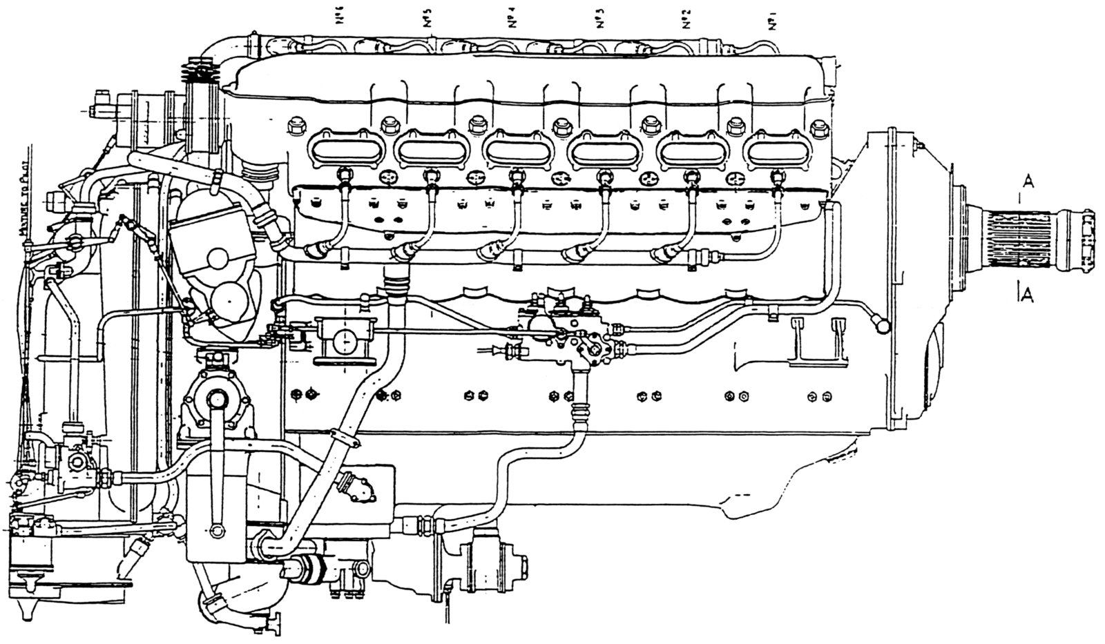 |
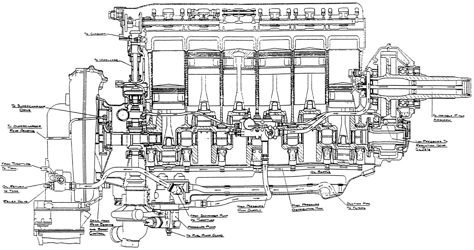
| Fig. 19. Merlin Mk 1 Longitudinal Section Showing Oil Pathways. Note fully counterweighted crankshaft and low position of the camshaft. (The Merlin Mk 1 Overhaul Manual) | Fig. 20. Merlin Mk 1 side view shows the low-provile valve covers, which cover the tops of the cylinder head bolts on the inside of the Vee, but leaves them exposed on the outside of each bank. (The Merlin Mk 1 Overhaul Manual) |
At Rolls-Royce, instead of taking off their jackets and sorting the Merlin problems out, they chose to simply dust off the old Kestrel, enlarge the capacity to 27 litres and put it back into production using the spurious title, Merlin II. The continuation of the name "Merlin" was a complete misnomer because if there was one characteristic that defined the Merlin and distinguished it from all other previous Rolls-Royce V-12s, it was the presence of a separate cylinder head. A more appropriate name for the Merlin II would have been "Kestrel Major", "Super Kestrel" or "Buzzard Junior" because in terms of construction, that’s all it was. However, to have dropped the name "Merlin" would have been a public admission of failure.
As mentioned earlier, the Kestrel was not a completely sound design as evidenced by the coolant leaks. With the introduction of glycol in place of water plus a requirement for the engine to overate at 3,000 rpm, to quote Tony Rudd, "One of my first experiences in the defect investigation department of Rolls-Royce (known as the Agard Street Irregulars) was with Merlin IIIs, Xs and XXs and the dreaded internal coolant leak, which was probably the most prolific Merlin defect during the Battle of Britain and into the year 1941."[2] This indicates fairly clearly that the resurrection of the Kestrel was a desperate measure.
L.J.K. Setright sums up Rolls-Royce engineering as, "A triumph of development over design"[7]. Well, not always. Over a period of 15 years production and through 20 different marks, development never triumphed over leaky liner joints! The only answer was to abandon the design; for the ramp head, the answer was the same.
As has been well documented, a flat-head, separate cylinder head version of the Merlin was designed and tested in 1938. It was later put into production at Packard in 1941 and in Britain in 1942 and it was only then that the true-Merlin line was reestablished.
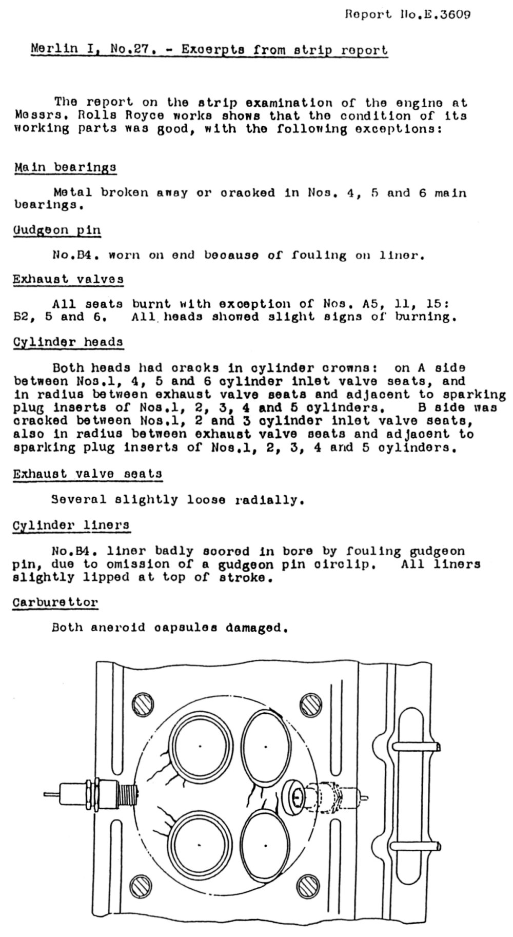 |
Testing the Ramp-Head Merlin Once the decision to series-produce the troublesome Merlin F had been taken, a pre-production batch of seven engines was built by the Experimental Department at Derby. The Works numbers for these units were 23, 25, 27, 29, 31 and 33 (Air Ministry Nos. A 112330 - 336). The first one was dispatched to Fairey Aviation; the second to Hawkers and the third, No. 27, was sent to R-R Hucknall for installation in one of their Hawker Horsley 2-seat, bi-plane, test bed aircraft. After fitting and checking, the Horsley was flown to Farnborough and handed over to the staff of the Royal Aircraft Establishment for an extended flight-test programme totalling 200 hours. The results were subsequently published in Report No. E 3609 (left). For the greater part of the period, the flight tests consisted of climbs at maximum permissible boost (+6 lb) followed by 5-minute full-throttle level speed checks at the full-throttle height. Endurance flights at different power outputs were also carried out. These tests took about five months to complete (November 1936 - April 1937) and at the completion of the programme, the Horsley was returned to Hucknall where the engine was removed. It was subsequently examined and analysed at the Derby works. In the R.A.E.'s hands, the engine performed quite well with very little maintenance being required although the carburettor had to be re-jetted to overcome a weak mixture problem before the testing proper could begin. The engine was run on DTD 230 fuel (87 octane + 5.5 cc/gal T.E.L.) which allowed +6 lb (gauge) of boost to be used quite safely. Thermostats for controlling the coolant (pure glycol) temperature without affecting the rate of circulation through the engine were trialled. There were two of these in the cooling system but the R.A.E. report does not say where each one was located. The initial devices failed to maintain the coolant temperature at sufficiently high values during glides so a second pair was fitted and these kept the engine outlet temperature at about 96°C, which was regarded as being satisfactory. Four sets of KLG spark plugs were used during the four months of the test. It was found that the inlet plugs needed to be cleaned every 14 hours while the exhaust plugs required attention after only 9 hours of service. Clearly, some development in this area was needed. However, while the engine completed this particular flight test quite well, when it was stripped the cylinder heads were found to be badly cracked. The report states, "These cracks, in 11 of the 12 cylinder head crowns are however, serious defects which could limit the useful life of the engine." The strip report appears at the left.. The test report ends with, "Flight tests are in progress on a Merlin II engine which has cylinder heads integral with the cylinder blocks and flat cylinder head crowns similar to those on the Kestrel engine." This is a strong indication that the R.A.E. felt that the Merlin I, as a design, would have a limited life. |
The Aftermath
According to long-serving Rolls-Royce and Bristol engineer, Stanley George Hooker, a favourite axiom of R-R managing director, Ernest Walter Hives was, "If the engineers are wrong, then we are all wrong!" In the case of the Merlin ramp head, the engineers weren’t just wrong, they were very wrong, terribly wrong, horribly wrong. The ramp head was flawed on two counts. First, the cube-on-a-cylinder concept didn’t work. Second, the decision to apply the ramp head design to the Merlin at its earliest stages was not a prudent one.
What was the cost of the debacle? In 1935, a production Merlin cost about £3,000; an experimental example about £6,000. So, 172 Mk 1 and Mk 11 prototypes total up to £582,000. In today’s values this equates to a staggering £29,100,000 or US $50,634,000! One can imagine the parliamentary and media furore that would erupt if such expenditure occurred in modern times to purchase sub-standard hardware.
A. G. Elliott should have been held accountable for the ramp head fiasco by R-R management and dismissed but three factors saved him:
1) Hives had just been appointed Managing Director and was still finding his feet,
2) The political situation in Europe was a major distraction, and
3) the Rolls-Royce "family" closed ranks to protect one of their own.
Elliott sailed through the whole affair unscathed and went on to serve the company for another 30 years.
The ramp head Merlin was a costly mistake both from a financial point of view and, probably more importantly, for the fact that it took two years out of the Merlin development programme at a time when, because of the impending war, time was a precious commodity.
| Rolls-Royce No. | Air Ministry No. | Type | Remarks |
|---|---|---|---|
| 5 | A111,137 | Merlin B | lst run 27 February 1935 |
| 7 | A111,138 | Merlin B | |
| 9 | A111,139 | Merlin C | |
| 11 | A111,140 | Merlin C | Prototype Hurricane |
| 13 | A115,735 | Merlin C | |
| 15 | A115,736 | Merlin C | Prototype Hurricane |
| 17 | A111,143 | Merlin C | Prototype Battle |
| 19 | A115,738 | Merlin C | |
| 21 | A115,73 | Merlin F | Spitfire prototype (2nd engine) |
| F23-35 | A112,330-36 | Merlin F | 7 built by Experimental Dept. |
| F37-61 | Al12,337-49 | Merlin F | 13 built by Production Dept. |
| 63-401 | A?-A? | Merlin Mk 1 | 170 built by Production Dept. |
| Total 199 | |||
| Source: Rolls-Royce Heritage Trust | |||
The Ramp-Head Merlin Today
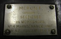
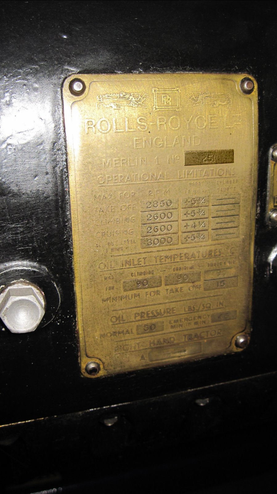
Only two examples of the ramp-head Merlin are still extant. Of the 20 Merlin Fs produced, 7 were built by the Experimental Department of the Derby works, followed by a batch of 13 on the normal production line. No. F.59, (Govt. No. A112,348), the 30th produced, was finished and inspected on the 11February 1937. Two days later, it was dispatched to the Fairey Co. at Stockport just south of Manchester. After service in a Fairey Battle it was removed and sent to the R.A.F. No.4 Maintenance Unit at Ruislip, London for overhaul. However, this did not occur; instead the engine was sectioned and set up as a display model. It is the oldest surviving Merlin Engine in the World.
In 1940, it was shipped to Auckland, New Zealand to be part of the New Zealand Centennial Exhibition. Due to the conflict, its return to the U.K. was delayed and finally it was donated to the Auckland War Memorial Museum.
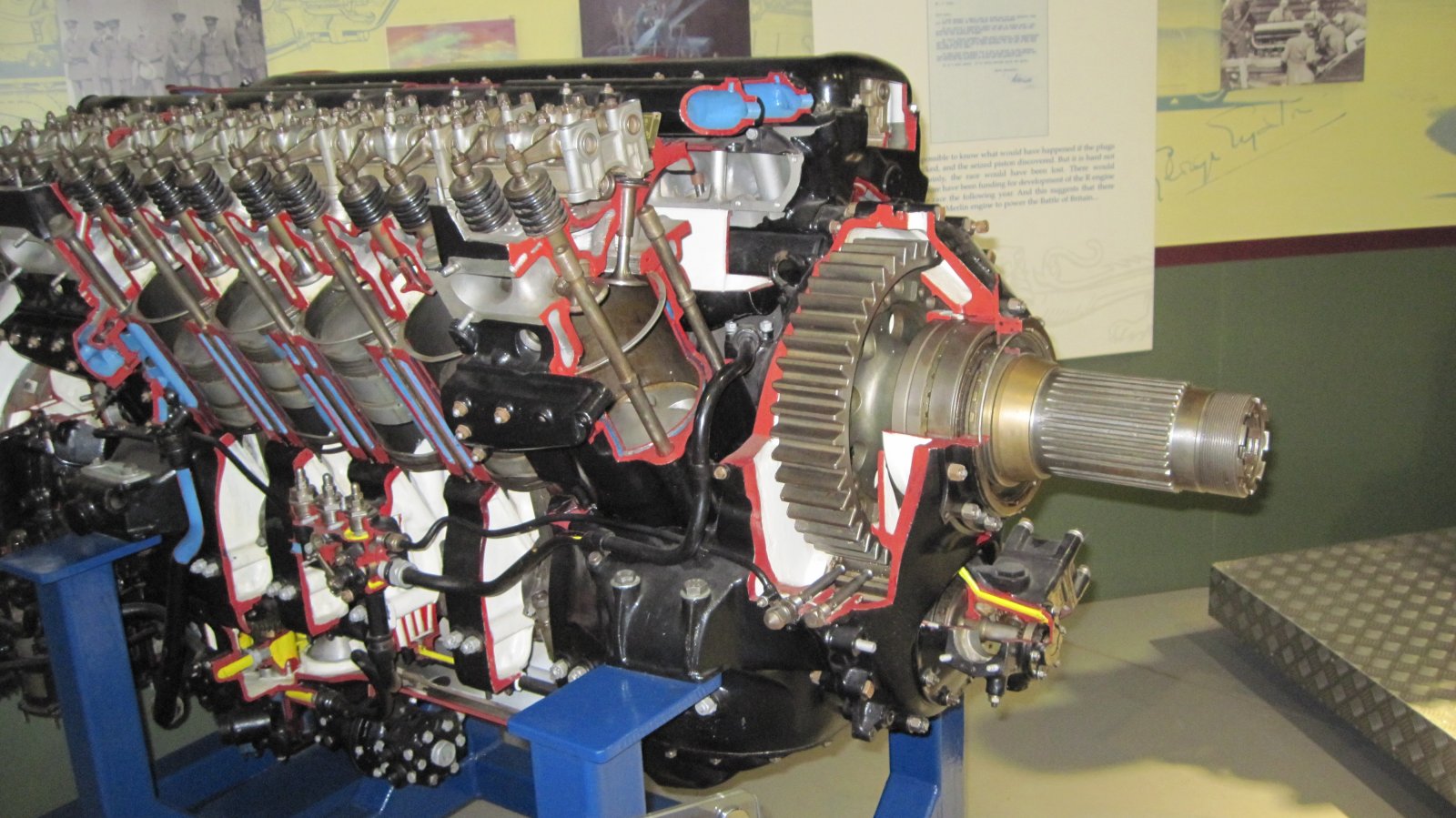
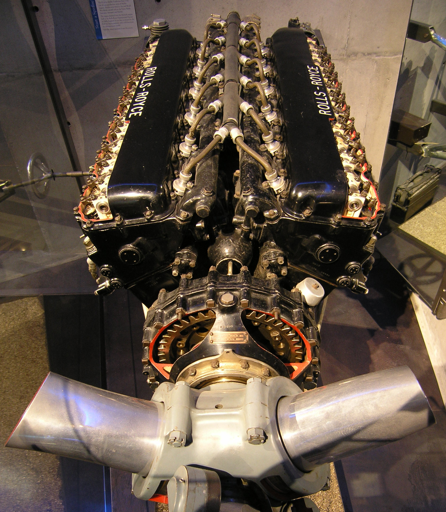
The other example is a Mk 1 now located in Derby, U.K., as part of the Rolls-Royce Heritage Trust collection. It is R-R serial number 251, which means it is the 126th Merlin built (Merlins were only ever allocated odd numbers). It is heavily sectioned.
 |
 |
 |
 |
 |
| World’s Oldest Merlin (Auckland War Memorial Museum) |
World’s Oldest Merlin (Auckland War Memorial Museum) |
World’s Oldest Merlin (Auckland War Memorial Museum) |
World’s Oldest Merlin (Auckland War Memorial Museum) |
World’s Oldest Merlin (Auckland War Memorial Museum) |
 |
 |
 |
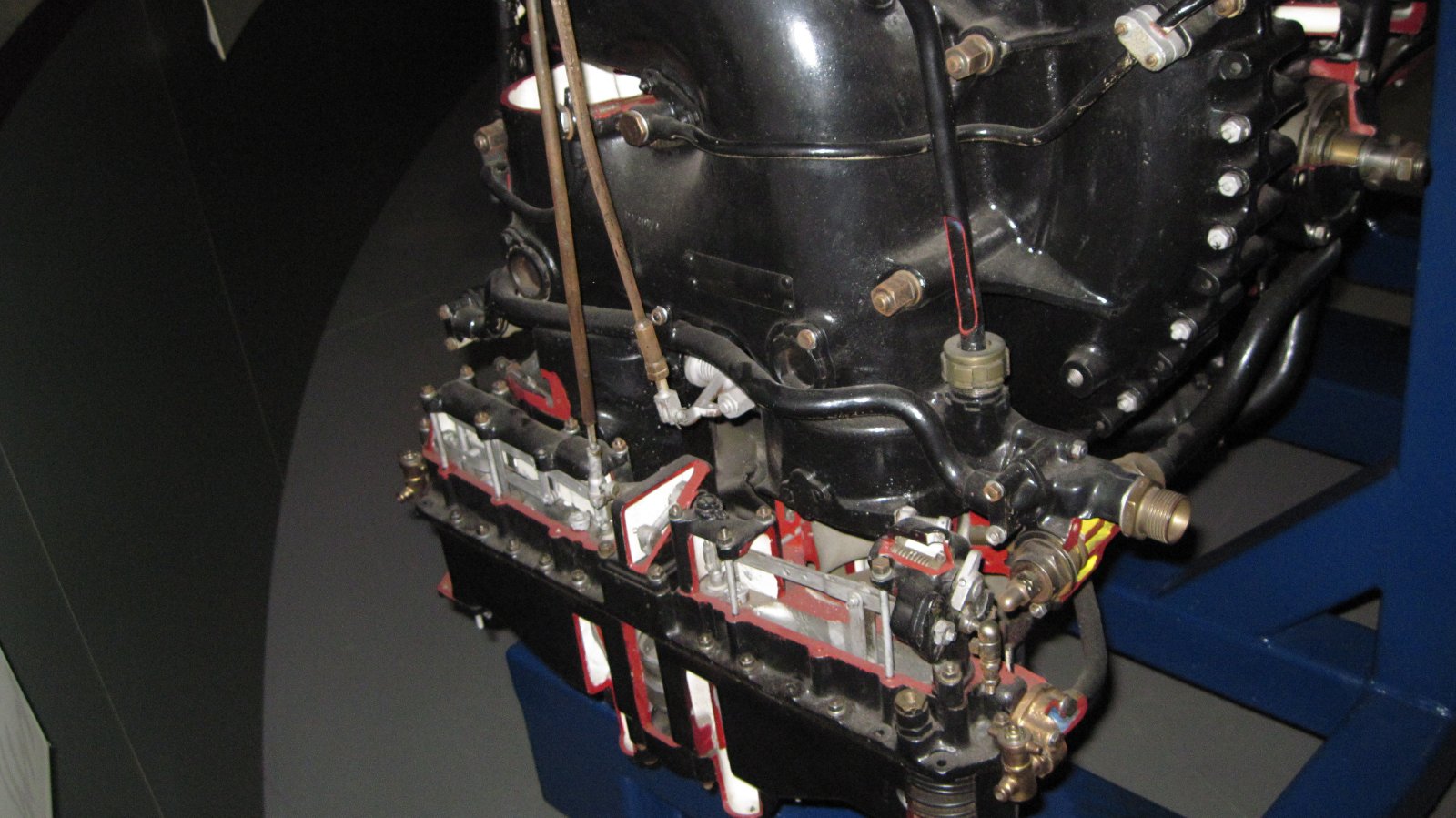
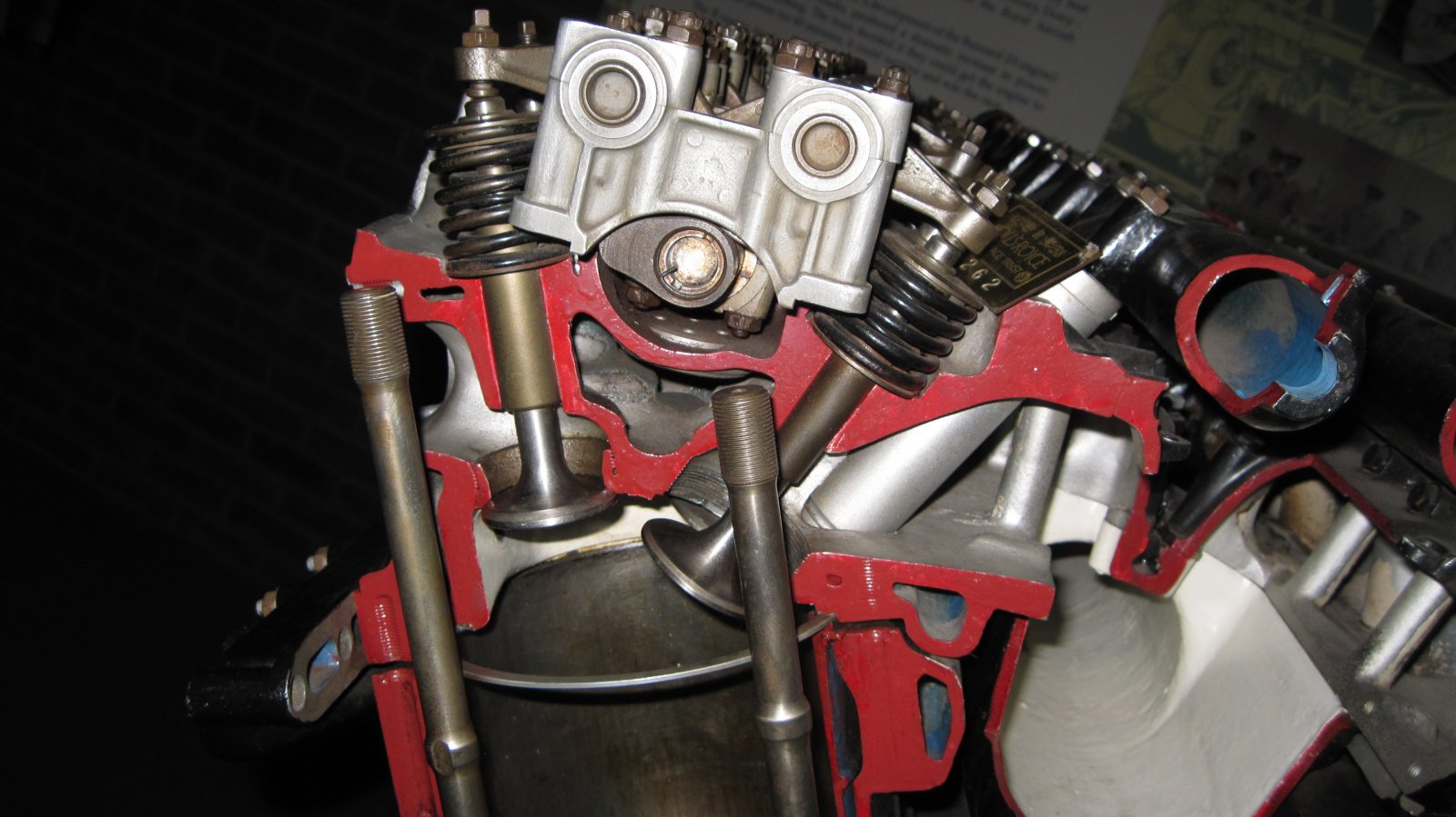
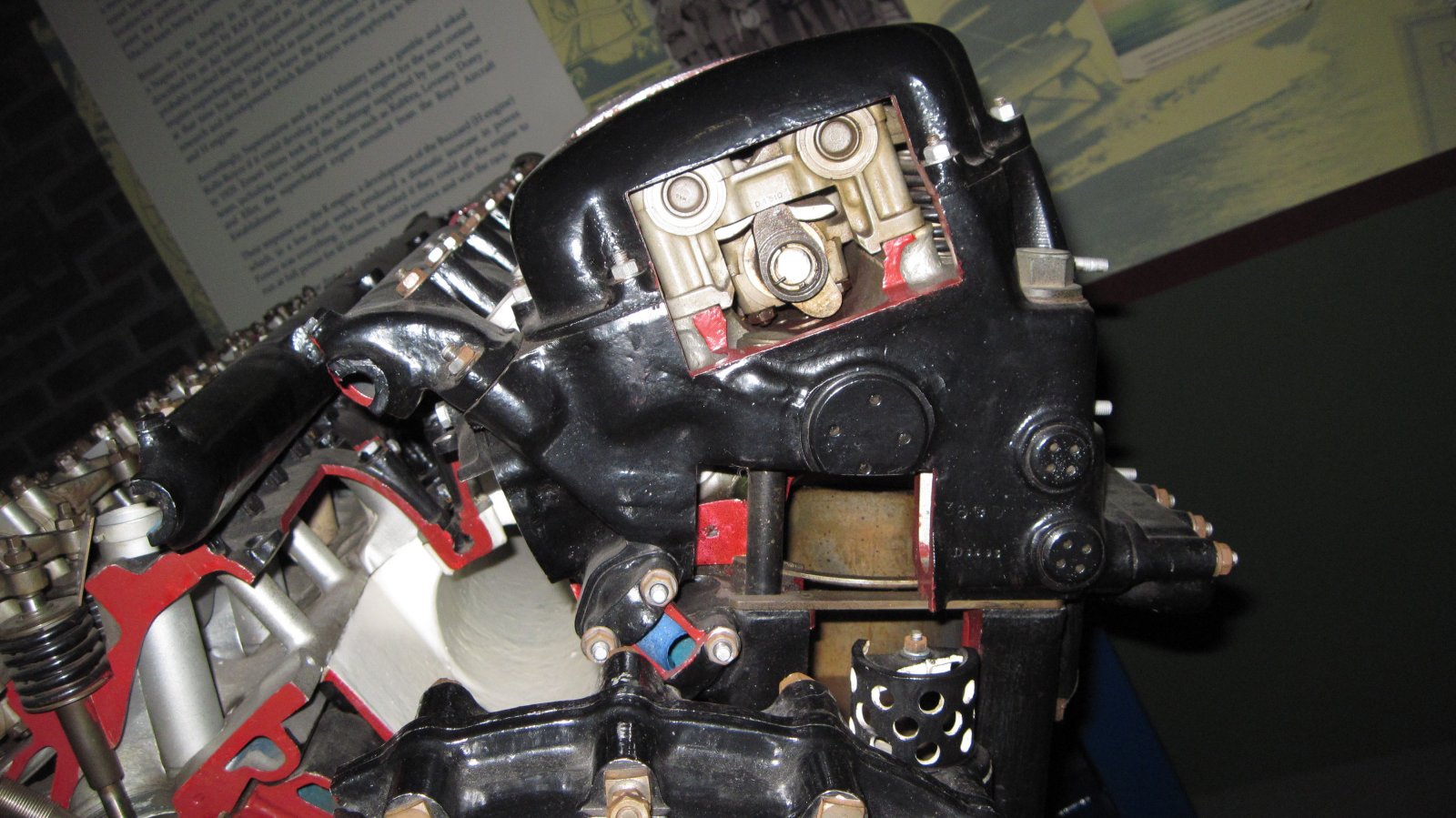
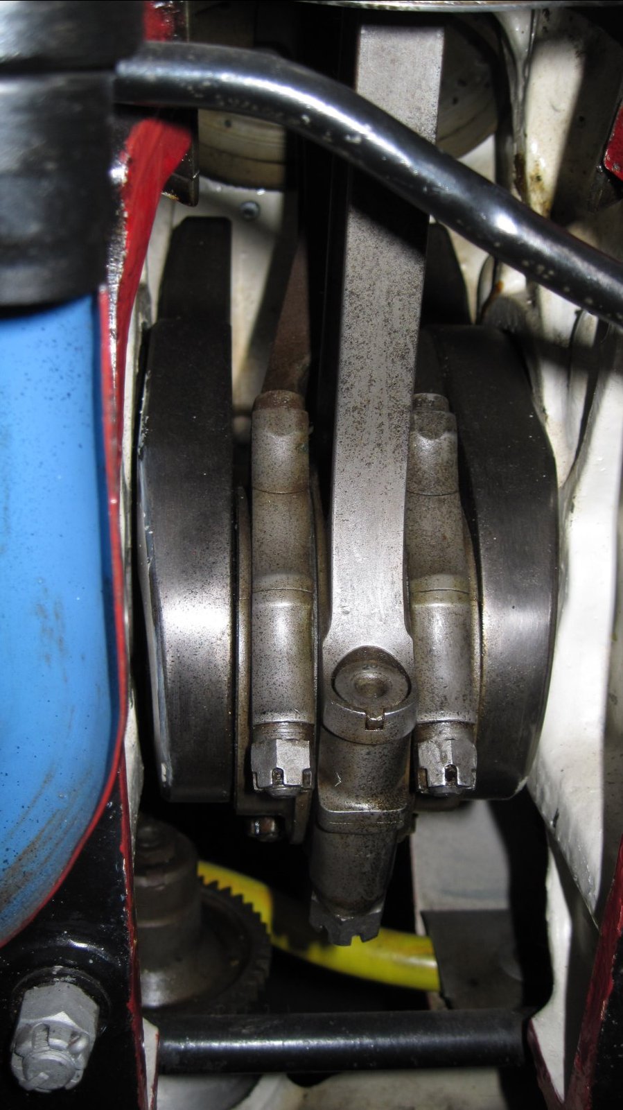
 |
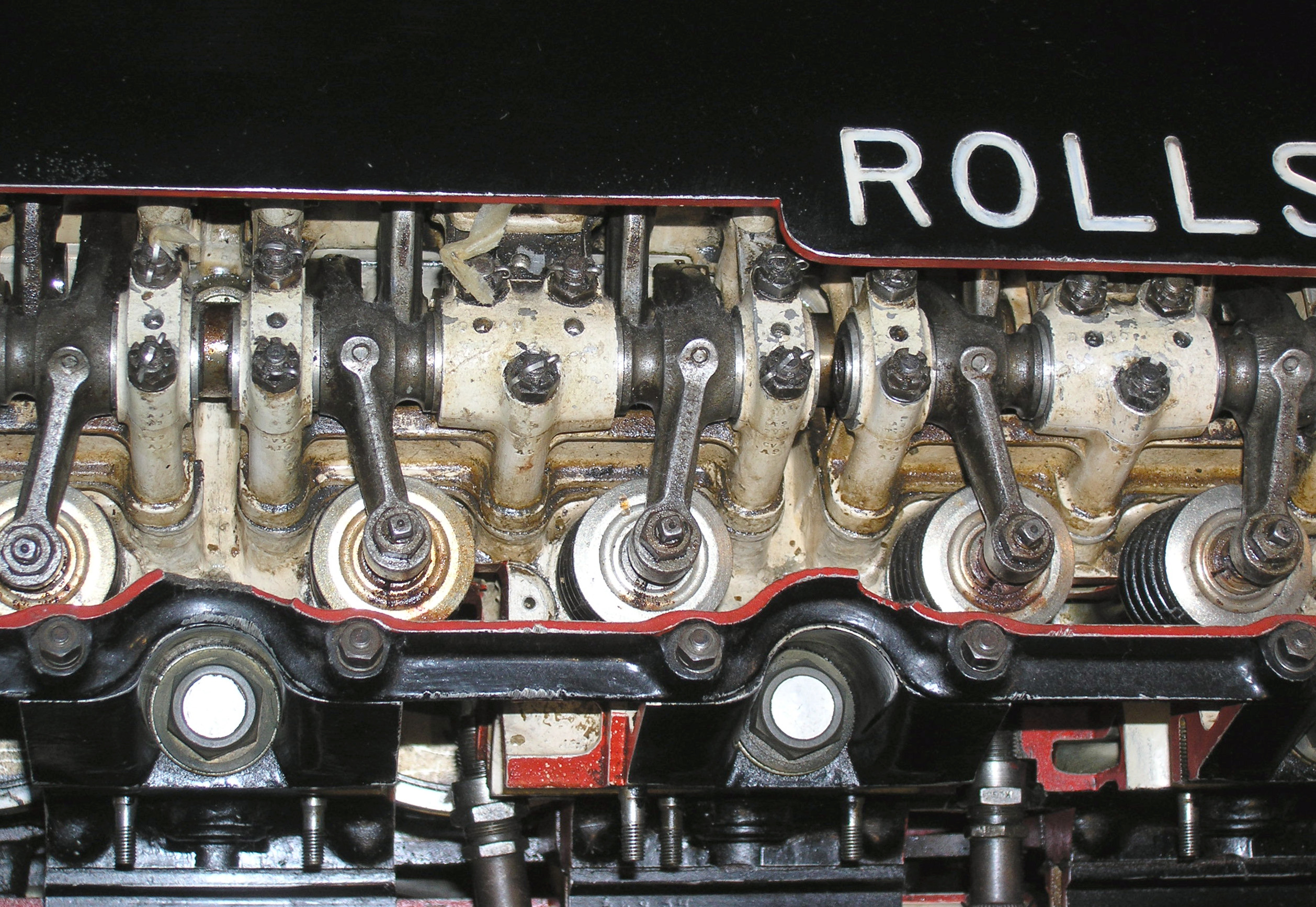 |
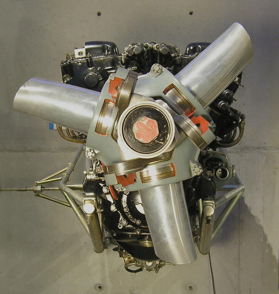
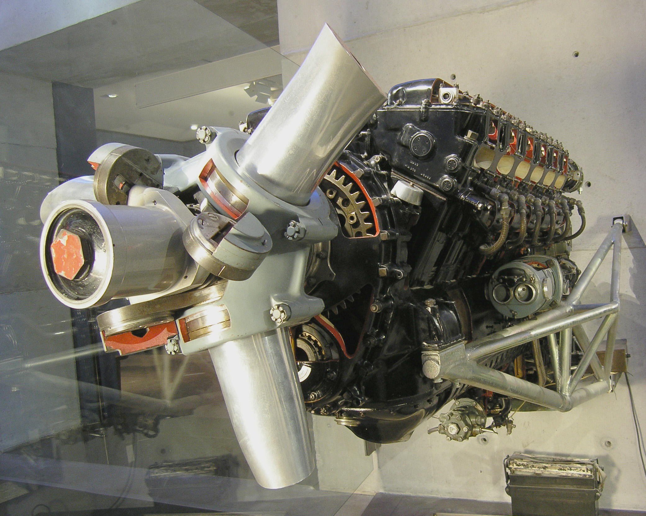
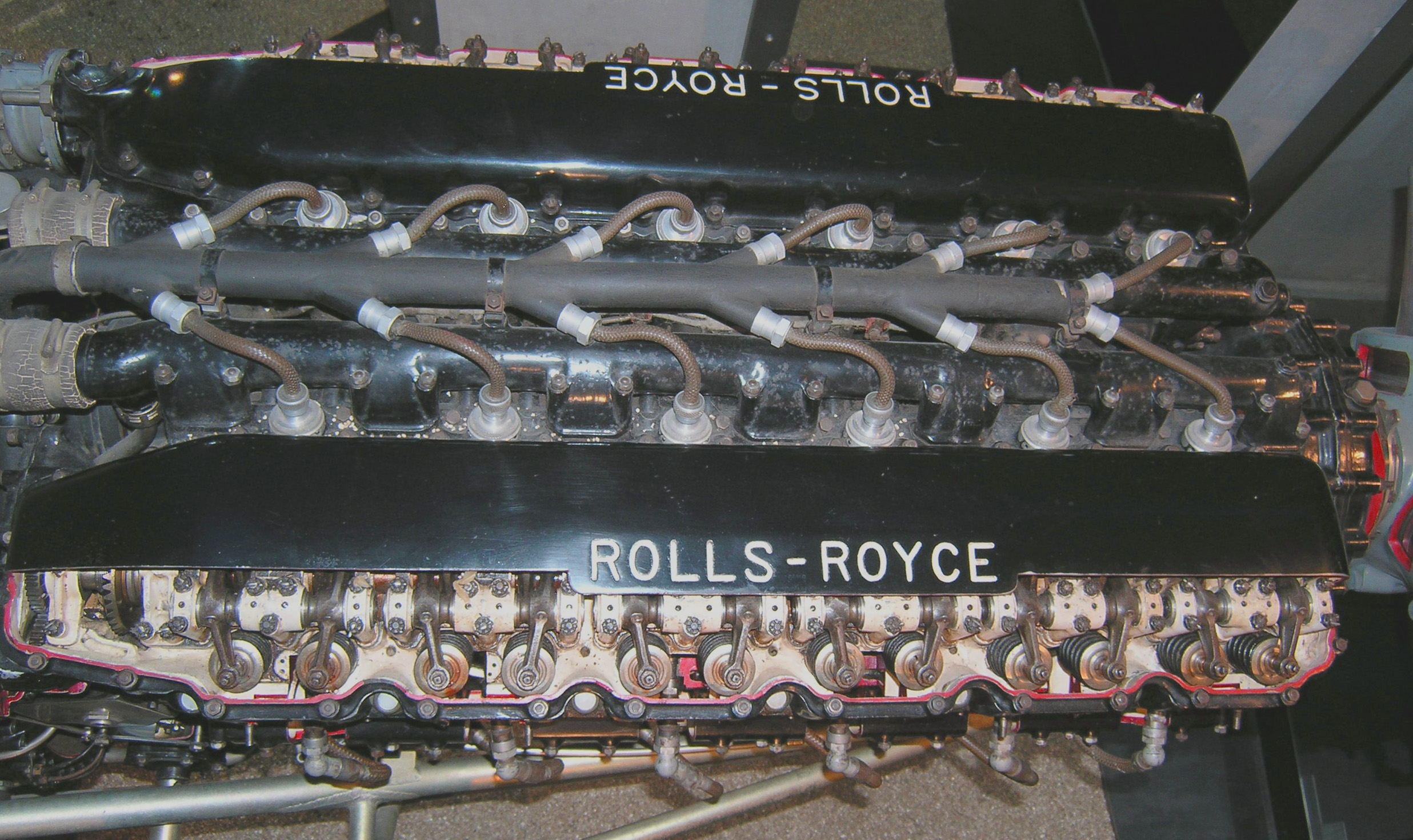
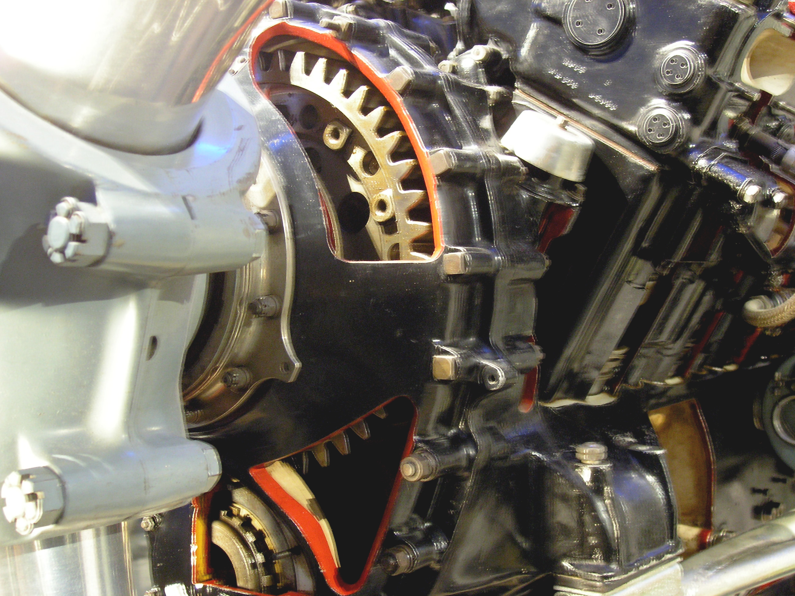
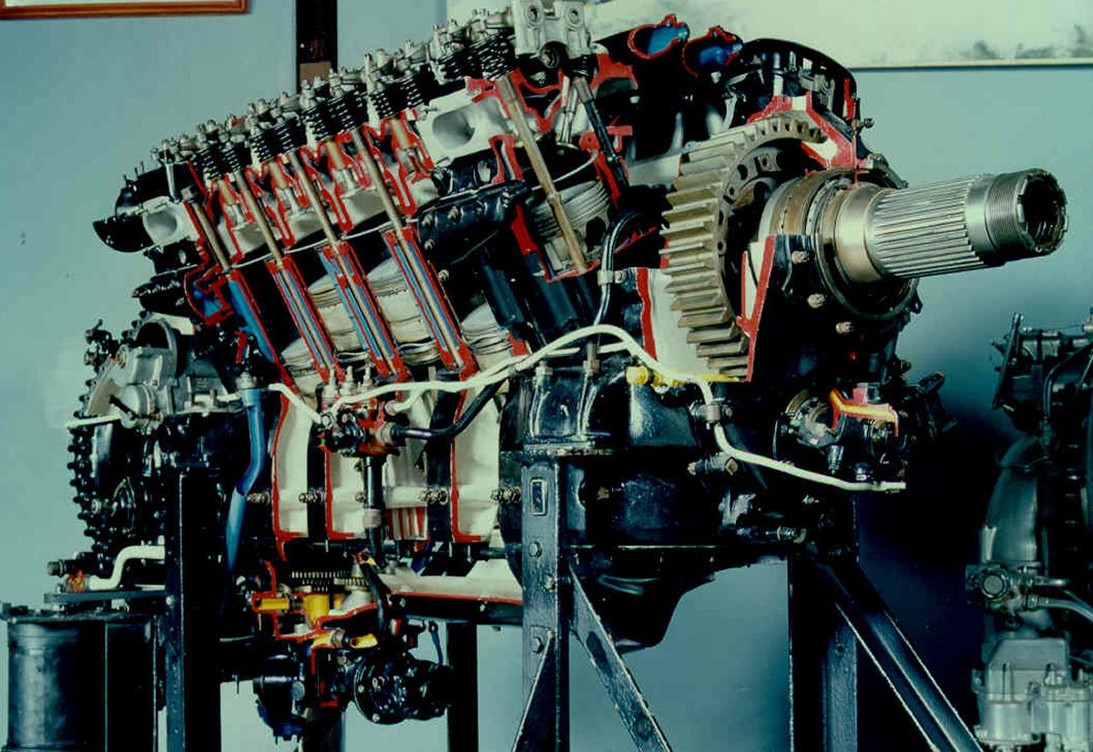
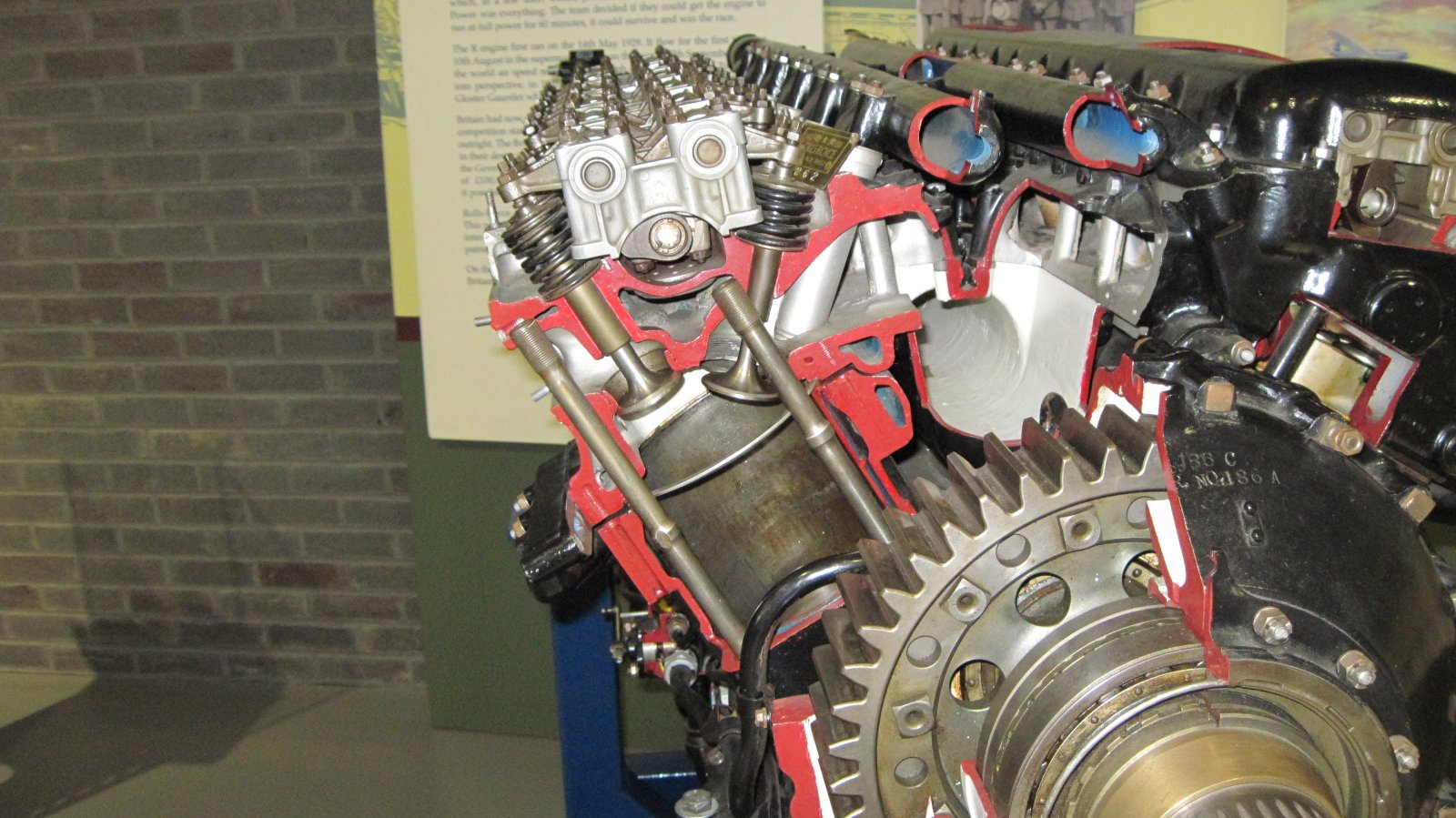
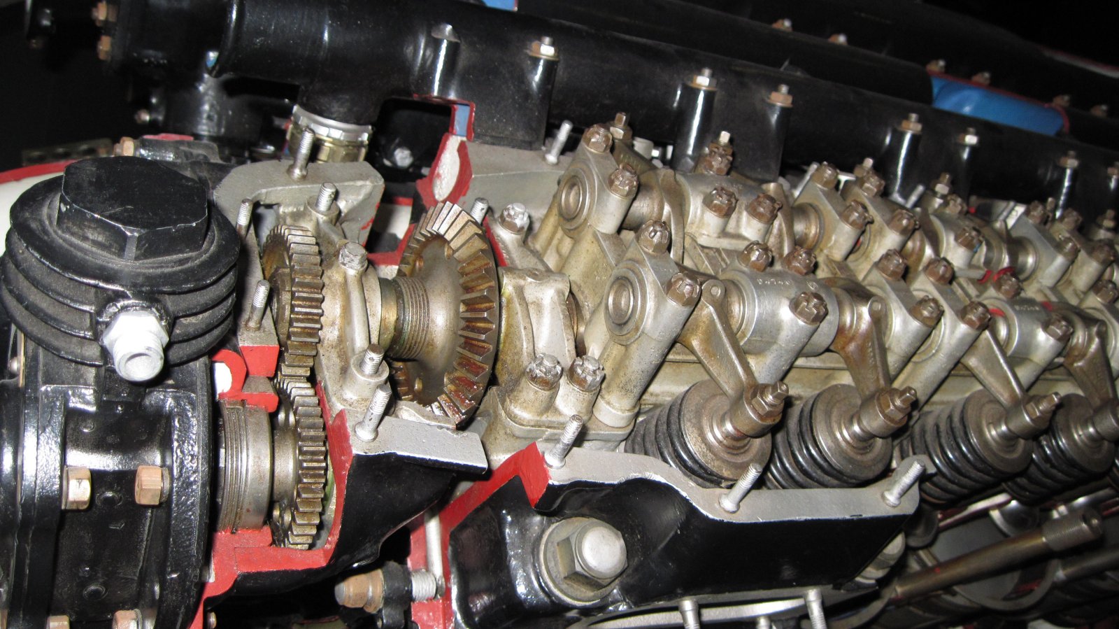
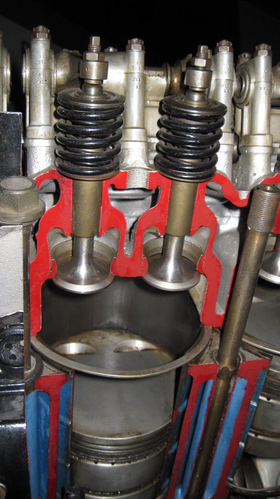
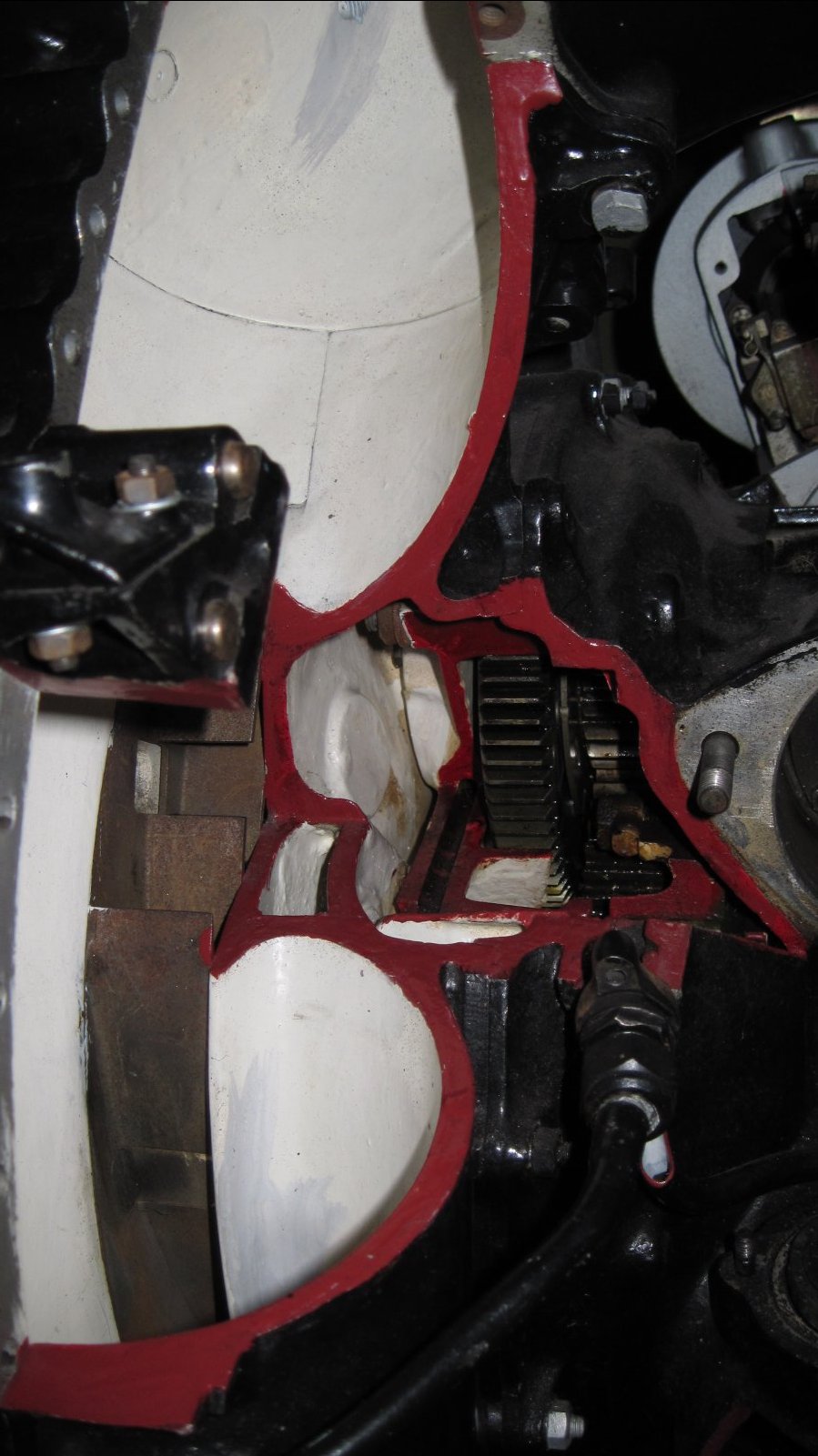
| Close up of he reduction gear and propeller hub of a ramp-head Merlin. Behind the gear casing the silver breather cap can be seen. Above the cap is the left cylinder head with the light-coloured head gasket clearly visible. (Auckland War Memorial Museum) | (Auckland War Memorial Museum) | (Auckland War Memorial Museum) | (Auckland War Memorial Museum) | Close up of the ramp-head Merlin valve gear mechanism shows exhaust valve rocker arms and their pedestals. Note that the cam shaft, which is normally a prominent feature of the Merlin valve gear, cannot be seen. (Auckland War Memorial Museum) |
Postscriptum
Since the writing and publication of the article on the prototype R-R Merlin engines (above), several interesting pieces of information have surfaced and are collected below.
In Summary
Table 2 is a summary of the Ramp-Head Merlin types although the top and bottom lines give the salient points of the models that preceded and followed the Ramp-Head engines, respectively, the PV-12s with their conventional valve arrangement and the Merlin Gs, which had cylinder heads and blocks of the same design as the Kestrel engines. The reference to the spark plugs as "adjacent" or "opposite" indicates that either the two spark plugs for each combustion chamber were side-by-side (similar to the DB 600/601 engines) or that they were conventionally disposed.
| Model | Rolls-Royce Engine Numbers | Upper Crankcase | Cylinder Head | Valves | Spark Plugs | Number Built | Cooling | Aircraft (Engine Numbers) |
|---|---|---|---|---|---|---|---|---|
| PV-12 Merlin A | 1, 3 | Integral with Cylinder Blocks | Separate | Vertical | Opposite | 2 | Water/Steam | Hawker Hart, K3036 |
| Merlin B | 5, 7 | Integral with Cylinder Blocks | Separate (Ramp-type) | Exhaust Valves at 45° | Adjacent | 2 | Glycol | |
| Merlin C | 9, 11, 13, 15, 17, 19 | Separate from Cylinder Blocks | Separate (Ramp-type) | Exhaust Valves at 45° | Adjacent | 6 | Glycol | Spitfire, K5054 (C9) Hurricane, K5083 (C11, C15, C17) Hawker Horsley, J8611 |
| Merlin D | There may never have been a "D" stage because it was hoped to put the Merlin into production after the C-models had been type-tested. The "D" prefix was allocated to Merlin production part numbers, e.g., Merlin F reduction gear casting = D 3400. |
|||||||
| Merlin E | 5, 7? | Separate from Cylinder Blocks | Separate (Ramp-type) | Exhaust Valves at 45° | Opposite | 2? | Glycol | Hawker Horsley, J8611 |
| Merlin F | 21-35 and 37-61 | Separate from Cylinder Blocks | Separate (Ramp-type) | Exhaust Valves at 45° | Opposite | 20 | Glycol | Spitfire, K5054 (F21) Fairey Battle (F17, F19) Hawker Horsley, J8611 |
| Merlin G | Separate from Cylinder Blocks | Integral with Cylinder Blocks | Vertical | Opposite | Glycol | |||
 |
Another Ramp-Head! It is now clear that there is a Ramp-Head Merlin extant in addition to the example on display in the Auckland War Memorial Museum in New Zealand. Merlin Mk. 1, No. 251 was been prepared for display during 2006/7 by members of the R-R Heritage Trust and is now on show at the R-RHT Learning Development Centre in Derby. No 251 was the 126th Merlin engine built. Status of Merlin F59 Having established that the Derby Ramp-Head is No 251, it means that example held by the War Memorial Museum in Auckland, NZ is definitely the oldest surviving Merlin engine in the World. |
| The Merlin Mk 1 at Derby, UK (Rolls-Royce Heritage Trust) |
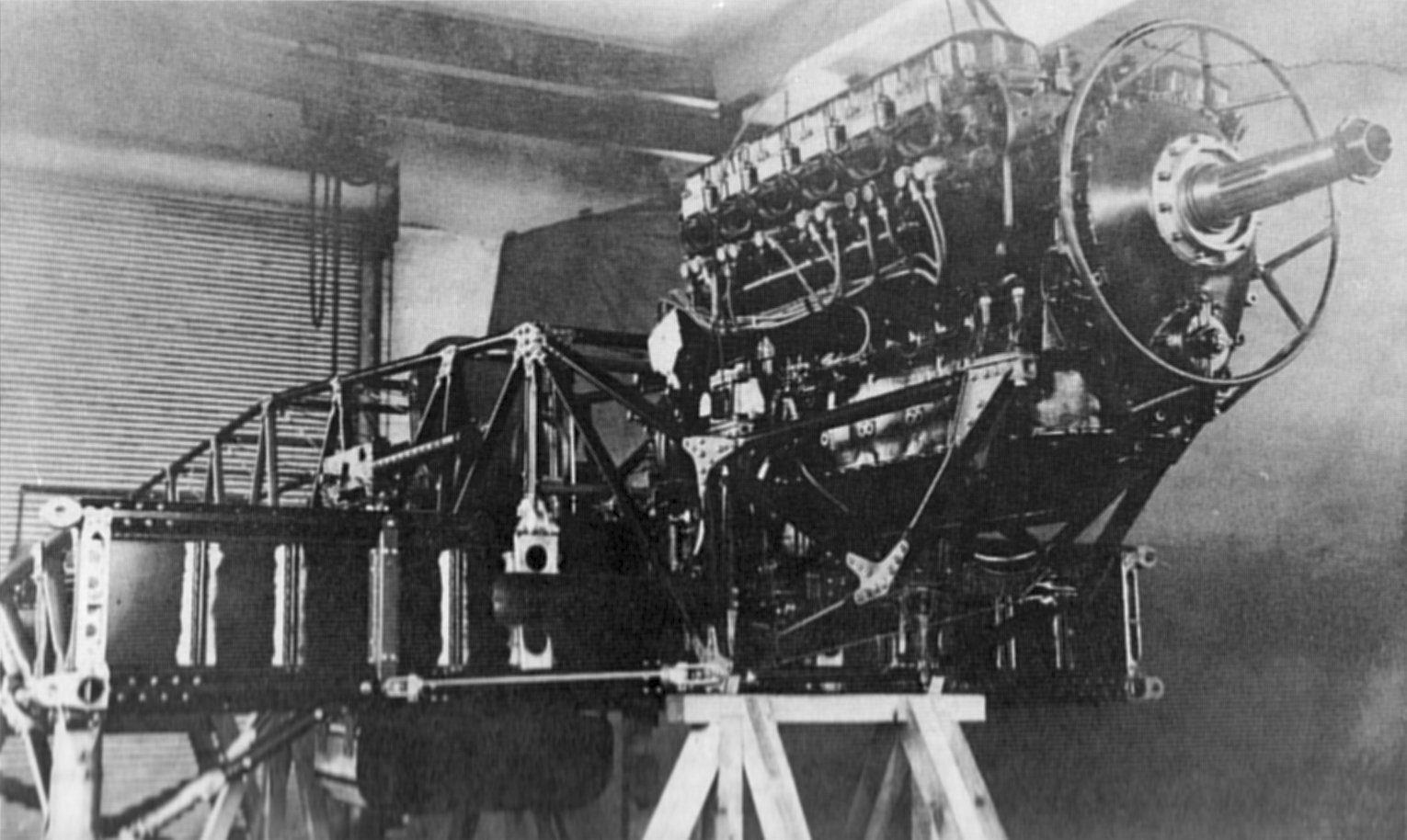 |
| Earliest Merlin Photograph (Patrick Stephens Ltd.) |
Earliest Merlin Photograph
On page 66 of the Patrick Stephens Ltd publication, Rolls-Royce Aero Engines by Bill Gunston, there appears a most interesting photograph of an early Merlin engine partly installed in the prototype Hawker Hurricane. The picture caption and associated text describe this engine as, "the eleventh Merlin C which powered the prototype of the Hurricane on its first flight." This description may need some review because Merlin "C11" was not the eleventh Merlin built. Merlin engines were only allocated ODD serial numbers by Rolls-Royce. This practice apparently stemmed from manufacture of the Eagle in WW1, where the Company was required to supply some engines with right-turning propellers and some with left hand airscrew rotation. Odd and even numbers helped to identify the differently set-up engines. Merlin engines had right-hand tractor propellers; therefore, odd serial numbers. (Griffon engines mostly had left-hand tractor props; therefore, even serial numbers.)
Thus, the reference to the Merlin in the photo should read "sixth Merlin C" (1,3,5,7,9,11,13 etc.) Merlin 21 would have been the eleventh one built.
Merlin C11 is often mentioned in the literature as the flight engine for the Hawker Hurricane aircraft which first flew on 6 November 1935. However, it is highly unlikely, given the trouble Rolls-Royce were having with the qualification of the Merlin, that the flight engine would have been delivered to Hawker Aircraft as early as the "Spring of 1935" (as the caption says), which is May/June in Britain. This would amount to six months before the first flight date. Also, it is plain to see from this photo that the airframe has quite a long way to go before completion, particularly in view of the fact that it was a hand-made prototype. Again, it is unlikely that the flight engine would have been supplied at this early stage.
Furthermore, the engine in the photo doesn’t look like a flight-ready motor. There are no covers on the exhaust ports and one of the plug leads is dangling. Neither is there any sort of protective cap over the prop-shaft. Not what one would expect to see on an expensive, prototype engine. Just under the horizontal engine bearer that joins the front and rear engine mounts can be seen five (of 12) machined holes in the right-hand side of the crankcase wall. From these holes should protrude the threaded ends of the main bearing-cap cross-bolts which would normally have appropriate castellated retaining nuts on their ends secured by split-pins. Clearly, these nuts and bolts are missing which suggests that this is a "hollow" engine, i.e., all the internal moving parts have been removed.
R-R records show that the two "B" engines, i.e., No’s 5 and 7 were converted to "C" models and, after testing, one was sent to Hawker Aircraft (on 26 August 1935) and the other to Vickers Supermarine for use as dimensional checks, particularly important in the case of the Spitfire aircraft which had very close fitting cowlings. Thus, the engine in the photo is more likely to be Merlin B/C7 (see Fig. 21).
Finally, it is a real curiosity that this picture should be the oldest image of a Merlin engine because, with all others of their aero-engines, R-R took greatest care to make sure a set of good quality photographs was taken.
The ’Phantom’ PV-12
One of the most enigmatic aspects of the history of R-R aero-engines is the complete lack of hard evidence for the existence of the PV-12 engine. All literature on the subject of R-R aircraft engines is full of studio photos that are obviously the product of the Company’s in-house photographic department. Going right back to Eagles, Hawks and Falcons, photos were produced, properly posed with the engines slung with ropes in front of a suitable plain background sheet and illuminated with special lighting. These studio-quality prints have been used many times by authors to illustrate their accounts of the aero-engine history of Rolls-Royce Ltd.
But the photo-sets of the PV-12 and the early B, C and E-model Ramp-Head Merlins seem to have vanished! Equally puzzling is the complete absence of any drawings of either the PV-12 or the ramp-head Merlins that preceded the F-model.
Many authors have chosen to write at length on the history of the Rolls-Royce Company during the latter half of the 20th century, including Nockolds, Lloyd, Harvey-Bailey, Schlaifer, Gunston, Lumsden, White, Bingham and Pugh, but not one of them has produced a photograph or drawing of the very important, seminal PV-12 engine and, more importantly, not one of them has ever questioned the absence of any graphic evidence of this engine in their works. Instead, they have all chosen to just rehash whatever Company hand-out was produced during the 1930s — a clear case of sheep following sheep.
So what happened to this important part of R-R history? There must have been hundreds of drawings made to create the PV-12 and dozens of photographs taken of the first one after it was built. That both drawings AND photos have disappeared suggests that the elimination of all this evidence was a deliberate action.
The only graphic evidence of the PV-12 I have ever come across ins contained in a patent filed by senior R-R designers A.G. Elliot, A.A. Rubbra and Thomas Shelly in early 1935 (Fig. 22). This patent is for the design of an arrangement to seal the lower joint between the steel cylinder liner and the cylinder block of a mult-cylinder liquid-cooled engine. The patent describes the engine as having "an aluminum alloy block", so presumably, this refers to an aero-engine, not a road vehicle engine.
Clearly, the cylinder head in the drawing is separate from the cylinder block and also obvious is that the shape of the combustion chamber is not of the ramp-type.
 |
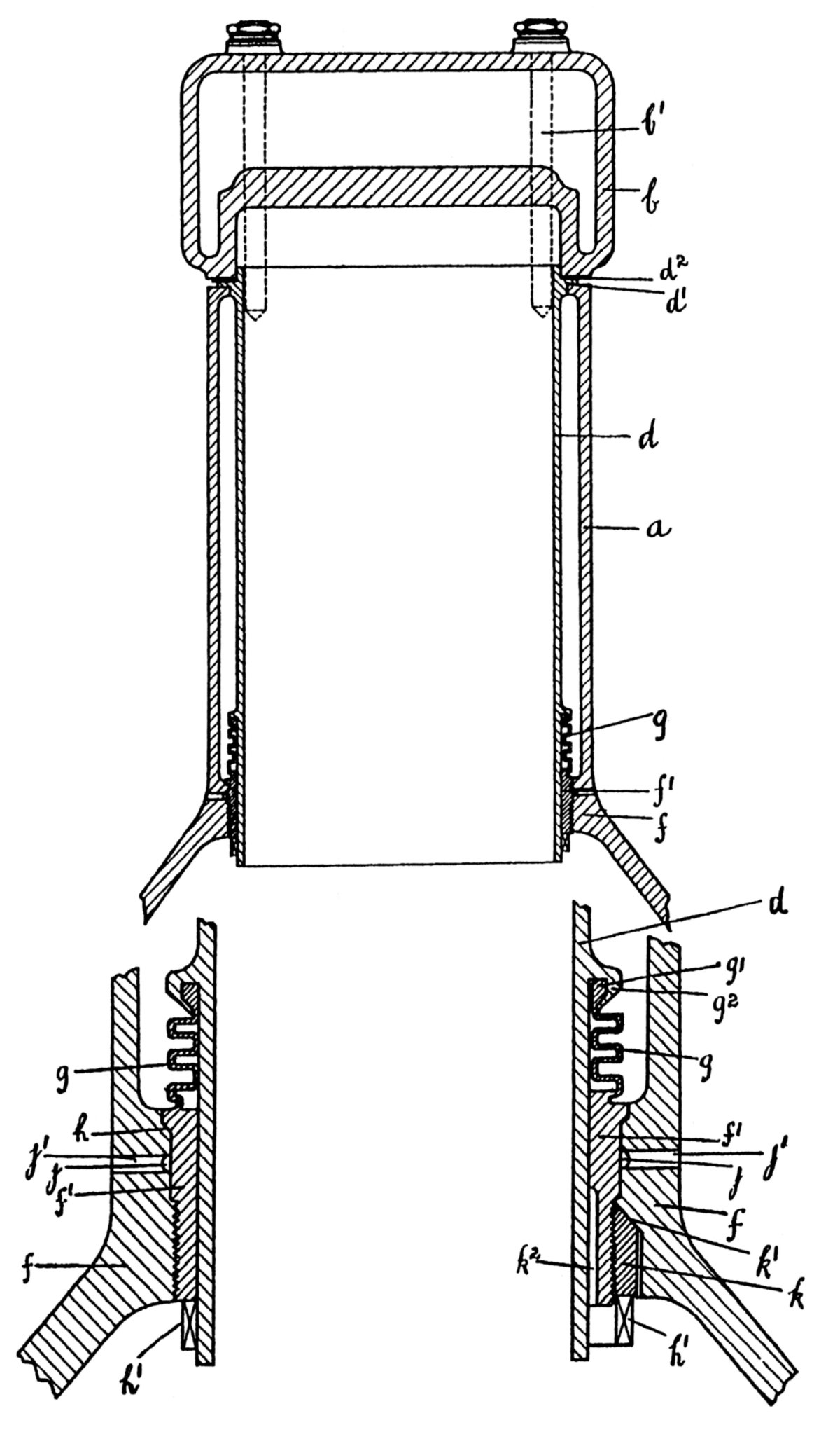 |
| Fig. 21. Drawing from Patent No. GB 310,146 Filed by Rubbra and Lovesey in 1934 Describing a Coolant Circulation Scheme. Note distinctive ramp-heads and one-piece cylinder blocks/upper crankcase, characteristic of the Merlin B. | Fig. 22. Drawing from Patent No. GB 448,054 Showing Separate Cylinder Head, Flat Combustion Chamber and One-piece Cylinder Block/upper crankcase. All are characteristic of the PV-12 (Merlin A) engine. What appears to be a break between the cylinder block and the crankcase is "an annular groove (j) drained by holes (j’)". |
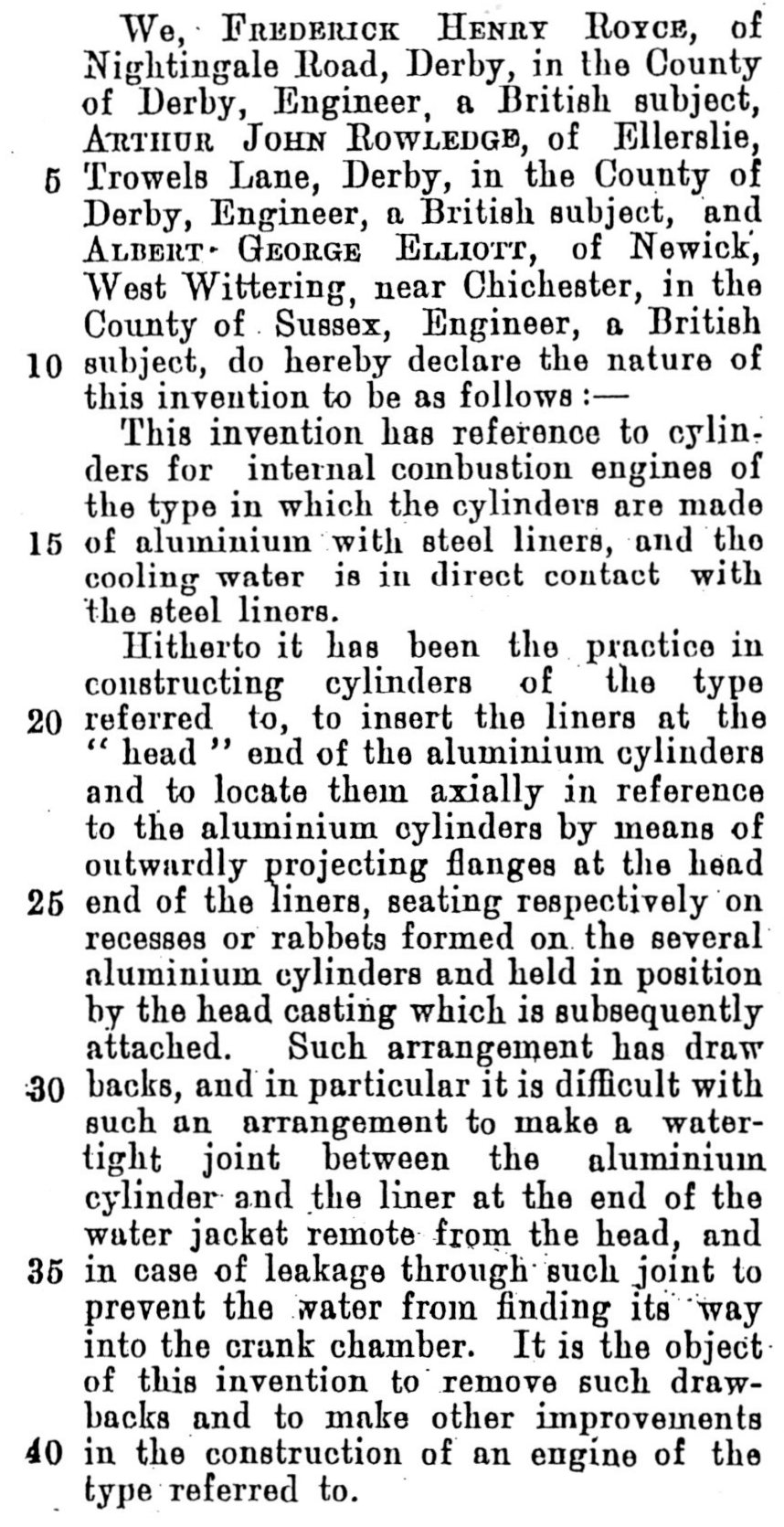 |
The Mystery of Patent GB 281,486 Most historical discussion and analysis of the Ramp-Head Merlin focuses, understandably, on the cylinder heads and the somewhat unusual valve arrangement that was employed. With regard to the design of the cylinder blocks, considerable thought had to be applied as to how the liners were to be located and sealed given that, with the use of separate cylinder heads for the PV-12, the Kestrel-type of water jacket was not a viable option. The design used, involving liner flanges arranged so that they could be clamped between the cylinder head and the top of the cylinder blocks proved to be both practical and effective in all models of the Merlin where it was employed. But where did it come from? Patent No GB 281,486 was written, in 1926, by the "big three" R-R designers of the time, namely, Royce himself, Rowledge and Elliott. It is a short document whose main function is to describe the Kestrel one-piece cylinder block design. The first three paragraphs appear at the left. The third paragraph is really interesting because it is a fairly accurate description of the PV-12/Ramp-Head Merlin cylinder design which only appeared seven years after this patent was penned! The first line of the 3rd paragraph is intriguing — "Hitherto it has been the practice in…,etc." because this begs the question, where had it "hitherto been the practice..."? The only wet liner monoblock aero-engine in existence in 1926 was the Curtiss D-12 and, in these motors, the liners were screwed into the cylinder heads to form a one-piece head-and-barrel assembly quite different from any of the Merlins. So, does, "hitherto it has been the practice..." refer to development lines within Rolls-Royce? The only monoblock engine produced by R-R prior to 1926 was the X-shaped Eagle XVI. The few accounts that exist of this engine all describe it as having dry liners. However, such accounts also claim that six Eagle XVIs were built which is quite a large number for a prototype design. Perhaps some were made with wet liners - after all, the Curtiss D-12 was the most influential aero-engine of that time and it had wet liners. Supporting this possibility is the part of the patent document, paragraph. 3, which describes leakage problems. To quote, "it is difficult with such an arrangement to make a water-tight joint between the aluminium cylinder and the liner...etc." Was this comment made as a result of first-hand experience? Whatever the explanation for the contents of Patent 281,486 actually is, the fact remains that the design for the Ramp-Head Merlin cylinder block had been thought out by someone at R-R many years before it came to fruition. |
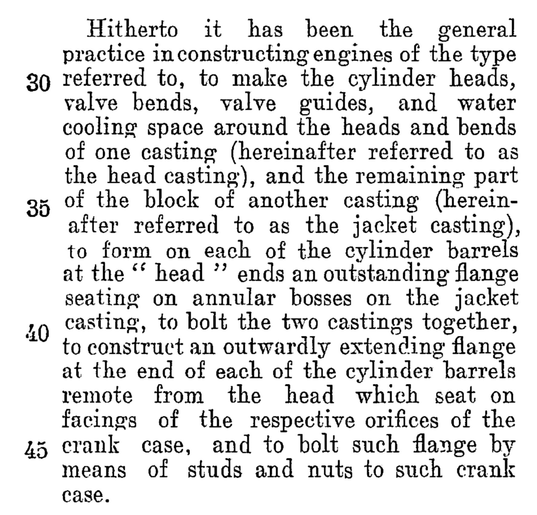 |
More Patent Intrigue In August, 1930, more than three years after the filing of the Kestrel cylinder patent, another on the same subject was lodged in the name of F.M.R. alone. In this document, (GB 310,146) there is contained detailed description of the Kestrel cylinder, presumably as Henry Royce, unencumbered by his two "star", in-house designers, would have really liked it to be! This later scheme differs from the original in two important ways: 1) there is a separate cylinder head and, 2) for each cylinder, there are six bolts dedicated solely to clamping the appropriate part of the (multi) cylinder head to the one-piece cylinder jacket. The seven pairs of long bolts holding each block of six to the crankcase are retained. This design is almost identical to the two-piece cylinder block version used in all the later Marks of the Merlin. The only difference is that the cylinder liner is still used as a structural member. With the upper liner flange clamped between the cylinder head and the jacket, the possibility of water or gas leaks from that joint was practically eliminated. Figure 23 shows sectional views of the cylinder. As with the earlier 1926 patent, this one contains a paragraph (left, lines 28 – 47) beginning, "Hitherto, it has been the general practice in constructing engines of this type..." A sketch of the cylinder description is shown in Figure 24. Although it is a feasible design, no engine featuring this cylinder construction was ever produced! |
 |
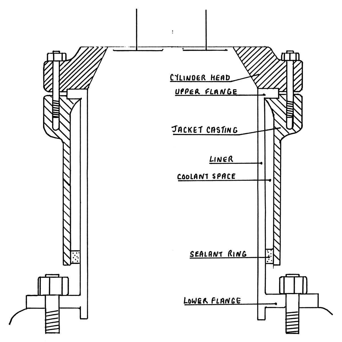 |
| Fig. 23. Drawing from Patent No. GB 310,146 Showing Sectional Views of the Proposed Kestrel Cylinder with Separate Cylinder Head. Note each cylinder bore is surrounded by six small bolts while the large, long bolts (h) secure the two-piece blocks to the crankcase. If this design had been used as a basis for the Merlin in 1933, events may have turned out very differently! | Fig. 24. Sketch of the Cylinder Construction Described by Henry Royce in Patent No. GB 310,146. |
P.P.S.
Throughout this summary, quite a few questions have been posed which indicates that the story of the Ramp-Head Merlin engines is still to be completed. As data bases expand and information becomes more freely available, no doubt all will be revealed in the fullness of time.
References
1. Rubbra., A.A. Rolls-Royce Piston Aero Engines. R-RHT, 1990.
2. Rudd., A. "The Merlin Lives On", S.A.E. No. 904,829.
3. Elliott., A.G. G.B. Patent No. 287,258. 1927.
4. Pearson., J.D. G.B. Patent No. 429,689. 1933.
5. Elliott & Pearson. G.B. Patent No. 431,144. 1934.
6. Elliott & Pearson. G.B. Patent No. 456,688. 1935.
7. Setright., L.J.K. The Power To Fly, 1971.
8. Hooker., S.G. Not Much Of An Engineer. 1984.
9. Harrison, C.E. Before and After the Merlin. 1984
10. Harker, R.W. Rolls-Royce from the Wings. 1976
11. R.A.E. Farnborough. "Merlin 1 and Horsley." Report No. E 3809. Jan. 1938.
Acknowledgements
Thanks to the staff of the Aukland War Memorial Museum for assistance in providing data and photos for this article.
Appendix 1 — The British Air Ministry and the "Dragonfly Decision"
Appendix 2 — The King 550 HP Aircraft Engine
Rolls-Royce Heritage Trust Merlin 1
Images by Kimble D. McCutcheon
 |
 |
 |
 |
| R-RHT Merlin Mk 1 | R-RHT Merlin Mk 1 | R-RHT Merlin Mk 1 | Cam and Air Pump Drive |
 |
 |
 |
 |
| Carburettor | Exhaust Ports | Cylinder and Valve Detail | Cam Profile |
 |
 |
 |
 |
| Fork and Blade Con Rods | Cylinder and Valve Detail | Supercharger Involute | Dataplate |
5 January 2014 — David Birch, of the Rolls-Royce Heritage Trust, has provided the following comments and additional information.
Jerry Wells’ article about the early Merlins made interesting reading, but I think his castigation of Elliott was a little over-stressed — as they say ‘the man that never made a mistake never made anything’. However, there are statements in the piece that require correction and enlightenment.
Although over the years it has been thought that the PV-12 was the Merlin Type A, there is no evidence to support this. No surviving contemporary or subsequent documents ever mentions the PV-12 being the Merlin A.
It is interesting to note that the Air Ministry allocated its numbers A109051 and A109052 to two ‘Merlin’ engines with the serials 1 and 3, against contract 231095/33 – the suffix denoting the year that the contract was placed. So, in 1933, the name Merlin had been chosen, and one might think that it must have applied to the PV-12s. But I don’t think it was.
At or about this time there was a proposal for a/the Merlin to be an inverted engine, and a wooden model of it was shown to a German delegation that visited Derby. This engine was never built. A time-line on the Merlin’s development, put together in the 1940s, states about the inverted engine ‘This was the first engine to be given the name Merlin’. The first PV-12 was built in this year, followed by a second, they being given the serial numbers 1 and 3. We cannot be absolutely certain that the two AM numbers were originally allocated to the inverted engine, but as things stand at the moment I think that they were. There is no mention in any document I have seen of engines bearing these AM numbers. I would like to disassociate the two PV-12s from these numbers, because in the first report on PV-12 running it says in the introduction ‘It was decided, since this engine was to be produced independently, to name it the PV-12’. No sign that this was a temporary designation until Ministry funding became available. It has to be said, however, that its limited flight development in a Hawker Hart was undertaken against an Air Ministry contract. Had the PV-12 been given the name Merlin in 1933 then it would have been known by it, irrespective of it being privately financed. Also, if a contract had been raised for two Merlins in 1933, then it is reasonable to assume that finance would have been available for them. It seems the PV-12 was just that, a private venture engine.
It is worth noting that when the Falcon XI and XII were named Kestrel, those types became the Kestrel I and II. One would have thought that the PV-12 would have been similarly amended to become the Merlin A. It also worth noting that in 1935 both PV-12s and both Merlin Bs were on test at Derby, each type with serials 1 and 3. Had the PV12 been the Merlin A then the two Merlin Bs would have been serialled 5 and 7. Contrary to what is stated in the article the first Merlin Bs were definitely 1 and 3. There is a photograph of Merlin number 1 as a Type C. Incidentally, this engine was sent to Canada, presumably as an instruction engine.
Regarding the engine installed in the prototype Hawker Hurricane on its first flight, this was indeed Merlin C number 11, but it was the sixth Merlin built, and only the fourth Type C. The AM numbers for Type C engines were A111137 to 111140. These were allocated in the batch A111137 to 111147, of which 111142, 111145 and 111147 were not used. Engine B1 is recorded as being either 111144 or 111145; I think the latter is correct. Engine B3 was 111146. I am not aware of any cancelled engines in the batch, so cannot explain why three numbers were not used, particularly so when engines 13 and 15 had AM serials A115735 and A115736, and engine 17 was A111143.
There was never any fear of the ramp head Merlin fighting in the Battle of Britain; its development had all but ceased by the time of the type-test of the Merlin G (Mk.II) in September 1936. The Merlin ramp head saga lasted but eighteen months, excepting the production of the Merlin Mk.I for the Fairey Battle. Very few of those engines were returned for repair/overhaul, being replaced by the Merlin II, (first delivered in August 1937) and the Mk.Is quickly sank out of sight.
I do not believe that the PV-12 was ever photographed; had it been so then a print would have surfaced by now. The old negative registers are extant and I have searched through them in the past looking for mention of the PV-12. There is none. As for drawings of the engine, they pre-dated the D-prefix series and were probably in the earlier A series, the great majority of which no longer exist. But we live in hope.
There was to have been a Merlin D; it would have had a two-speed supercharger drive, but was not built.
Until we can establish which engines would have/did have the A109051 and 109052 serials we are never going to get to the bottom of this mystery. If they were allotted to the inverted design then that engine has to be the Merlin A.
Send mail to
![]() with questions or comments about this web site.
with questions or comments about this web site.
![]()