
Napier Lion
Napier’s Redoubtable Lion
by Karl E. Ludvigsen CIMechE MSAE
Published 1 Jan 2020
Napier Lion |
Much like Leyland Motors under Parry Thomas, the distinguished London engineering company of D. Napier and Son, Ltd. saw an attractive option in the manufacture of aircraft engines in the course of the Great War. Established in 1908, when Scotsman David Napier came to London to seek his fortune, the company began with machinery for newspaper printing. The company led by David’s grandson had since 1900 been a producer of distinguished motor cars that proudly represented Britain in international racing. |
 |
| Montague Stanley Napier was the powerhouse behind the creation and perfection of the Napier Lion engine, whose attributes were so outstanding that the company relied on the Lion much longer than it should have. |
Under Montague Stanley Napier, born in 1870, the company established itself in works at Acton, West London in 1903. From its portals rolled nearly 2,000 vans, lorries and ambulances to serve Britain and her allies during the Great War. Interrupting this valuable service in August of 1915 was the government’s declaration that Napier was henceforward a ‘controlled establishment’, making what it was told to make. This meant aero engines, which Britain’s airframe makers urgently needed.
One such was a dated design from the Royal Aircraft Factory, its Type 3a V-12. A water-cooled version of a Renault engine rated at 200 bhp, it was made at Acton in a run of 260 engines. Also assigned to Acton was a Sunbeam design, the Arab. An overhead-cam V-8 made largely of aluminium and promising 200 bhp, it caught the fancy of the War Office which issued orders for 3,000 after the bench-tests results of a prototype. By the time 590 had been made and delivered, however, largely by Sunbeam, its vibration was judged ‘alarming’ and ‘terrible’, as a result of which the engine was ‘entirely useless’.
‘Montague Napier was not the man to make a faulty engine with an easy conscience,’ wrote Napier historians Charles Wilson and William Reader. ‘He became convinced that he could himself design an engine that would be better than any of those which he was being asked to build and he determined to set to work. He seems to have found some difficulty in persuading his fellow directors that he was right, or else he did not feel justified in committing the company to expenditure in backing his opinion until he had verified it by experiment.
‘At any rate,’ the historians continued, ‘he proposed to finance the early work himself on the understanding that if a successful engine was the result, he should have his money back from the company, and also a royalty on any engines that were made to his designs. He found less difficulty in persuading the naval and military authorities, no doubt because he was not asking them to put up any money, and they agreed to see that he got all the materials he needed. The negotiations came to a head in July 1916. When they were concluded Napier began to develop his own ideas for an aircraft engine.’
Having served apprenticeships in the bowels of the Napier works, Montague Napier was steeped in its proud engineering principles. Applying for his first patent at the age of 24, Napier would ultimately have 38 to his name, including foreign applications. Thus he was well placed not only to contribute to the engine’s creation but also to lay claim to royalties on its production. In fact around the time of his commitment to the aero-engine project his failing health—thought to be caused by cancer—led to his relinquishing of management roles in favour of a concentration on engineering. Seeking the curative benefits of warmth, in 1917 Napier moved permanently to Cannes in the south of France.
After Montague Napier’s physical decline, said Wilson and Reader, ‘the policy which he enjoined upon the firm began to bear a striking resemblance to the policy of his father except that financially it was much more successful. It showed all the hereditary talent for engineering, all the hereditary dislike of flamboyant salesmanship. It relied for success on the superlative quality of the goods produced. It looked towards the Government as the chief source of business. It meant that the firm would remain relatively small and very highly specialised, rather than becoming a giant of mass-production. And it was a policy which a sick man in France could continue to control.’
Napier implemented this control through Harry Tempest Vane, the company’s acting chairman and director. Essentially a car man, Vane would become chairman after Montague’s death in January of 1931 but resign in 1932 when his ideas of reviving auto making were not welcomed by the board.
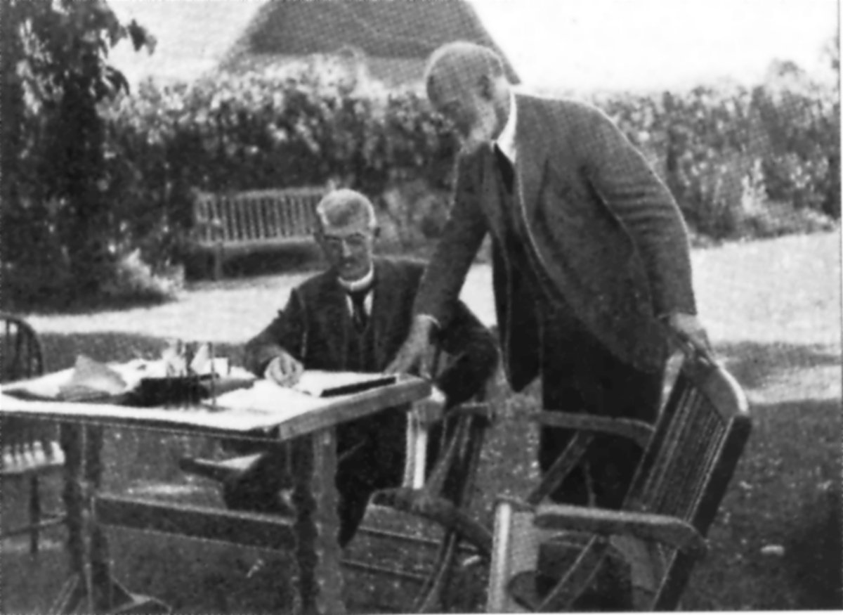 |
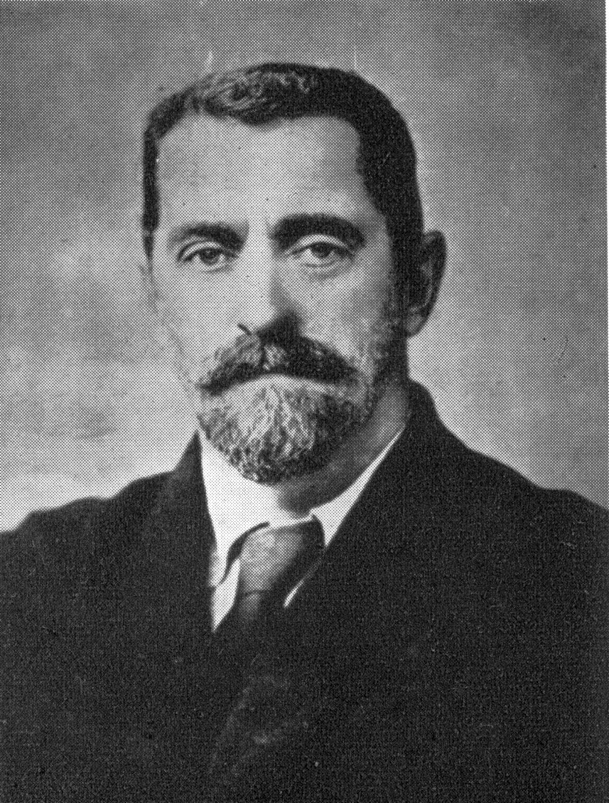
| Arthur John Rowledge, seated, is seen in company with Sir Henry Royce, whose company he joined after his work on the Lion at Napier. A close friend of Reid Railton, he contributed greatly to the later success of Rolls-Royce aero engines. |
Napier’s engine-design right hand in Acton was the son of a bricklayer whom he had hired as chief draftsman in 1903 and promoted to chief designer in 1913. Six years younger than his Cannes-based chief, Arthur John Rowledge had matured as an technician under the demanding tutelage of perfectionist Montague Napier. As they began to work together on their own aero engine each made contributions. In fact although Rowledge is widely celebrated as the designer of the Napier Lion engine, it was equally the product of the intellect and experience of Napier.
Sensibly consulting with the Air Ministry to gain an understanding of their requirements, Napier and Rowledge were told that a desirable engine for their purposes would produce 300 bhp at an altitude of 10,000 feet and would not be run at full throttle below that height. Pioneered by Junkers as well as Georg Bermann for BMW, this concept was rapidly spreading among German engine builders including Opel and Maybach. Napier was invited to create a similar ‘overcompressed’ engine, in which a key element would be a higher-than-normal compression ratio.
A fundamental decision would be whether the new engine would be cooled directly by air or indirectly by water. Rowledge explained why water cooling was their choice: ‘We may claim for the water-cooled engine that almost all the great performances in the air have been accomplished by machines fitted with this type of power unit, since the days when the brothers Wright fitted a four-cylinder water-cooled engine in their machine and succeeded in making the great advance in flying with which their name is associated. Further, we may always expect that it will be possible to build a faster machine with a water-cooled engine than with an air-cooled engine. With water cooling the temperature of the engine is under better control to meet the great variations of temperature met with in flying at different altitudes. The problem of heating the mixture pipes and the carburettor is also considerably simplified.’
The two engineers cast a rule over the specific requirements of the engine they were to create under Napier project number E64. For faster fighters and heavier bombers they needed at least 450 horsepower. This pointed to a 12-cylinder engine, albeit one with the lightest practicable weight. [Initially the designers considered an 18-cylinder triple-bank engine under their project E59 but reverted to the 12-cylinder configuration over concern about crankshaft torsional resonance.] Low fuel consumption would be a criterion together with a shape amenable to packaging. To meet these parameters they created a type of engine that had not hitherto existed.
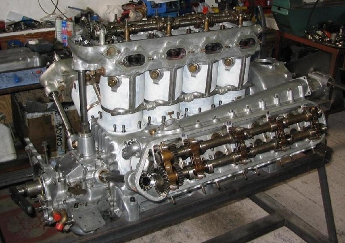
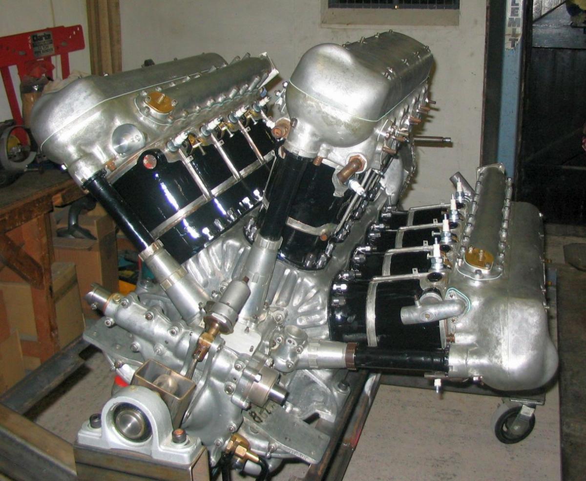
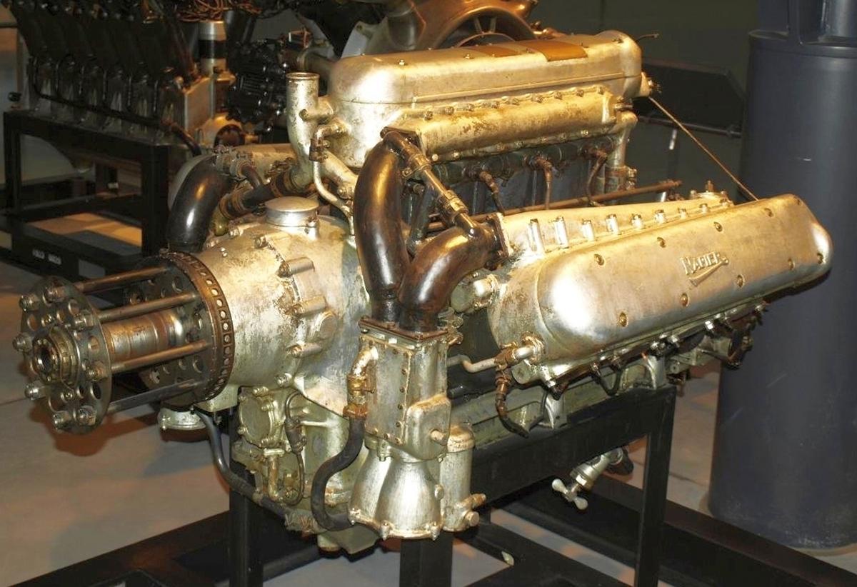
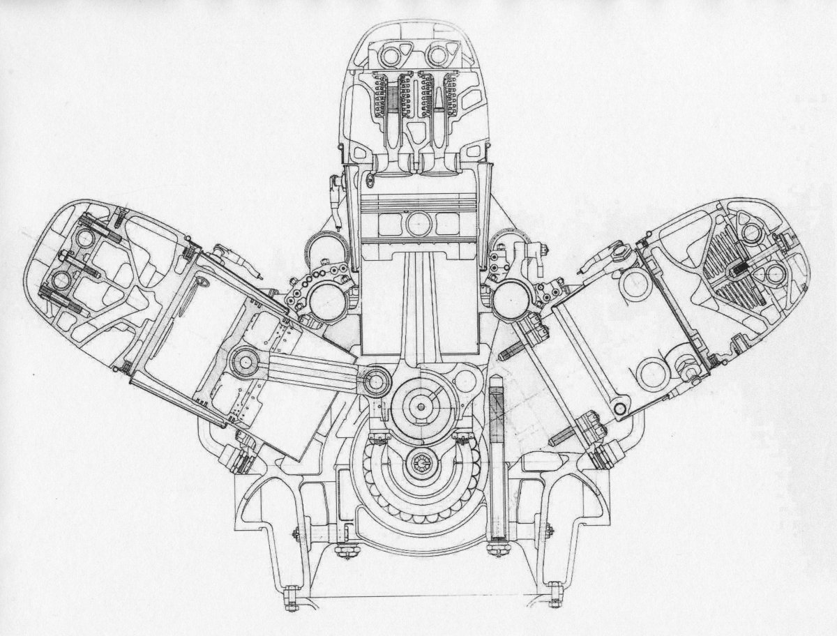
Vee-type engines, those with two banks of cylinders to cluster more of them around a crankshaft, had been common for decades. The first 12-cylinder vee was built in 1904. Napier and Rowledge saw no reason why they could not cluster the same number of cylinders more compactly by having three banks with four cylinders each. Good spacing of the banks to achieve regular firing was 60 degrees, with one bank of four vertical at the centre and the other two splayed out to the left and right. The angle also left ample room between the cylinder vees for induction and exhaust manifolding. This was the first time that a large engine of what became known as a ‘W-type’ came into existence. The few preceding it were small ‘fan-shaped’ engines for light aircraft, such as British Anzani’s three- and six-cylinder designs.
Initially known at Napier as the ‘Triple-Four’, this engine had a crankshaft like that of a four-cylinder engine. The challenge was the successful attachment of three connecting rods to each of its four rod journals. While later bearing technology would allow three rod bearings to share a journal side-by-side, this was infeasible at the time. The options were a variant on the fork-and-blade system, in which one rod bore on the journal and sisters bore on surfaces in the forked rod, or the use of a master rod and articulated link or links.
Like the fork-and-blade method, a master rod with links allowed cylinders to face each other directly to create a light and compact engine. The Lion’s I-section master rod looked conventional, with a big end that occupied the full crank journal. On both sides of its big end were lugs holding pins that connected to link rods to the pistons in the outer cylinder banks. Master and link rods were joined by pins not unlike wrist or gudgeon pins. All three rods carried external tubes to lubricate their gudgeon-pin bearings. Initially tubular, the link rods were later I-section.
Although not elegant-looking, the articulated link was in fact a valid and often-used mechanism for vee-type engines. A plus was that its reciprocating masses were the lightest of all three solutions; a minus was that the link’s shortness generated higher lateral forces on the piston. Thus the link-rod system was widely used in vee-type aero engines following the early example of Renault’s successful designs and the Royal Aircraft Factory’s similar engines, including its Type 3a V-12 that Napier had abortively produced before designing its own engine. [That the principle could be used either well or poorly was illustrated by the Sunbeam Arab V-8 mentioned earlier, another design with which Napier had direct manufacturing experience. Its articulated-rod system was blamed for its excessive vibration.]
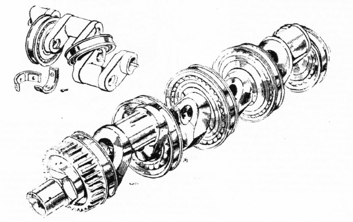
Crucial to the success of such a high-density engine was a robust crankshaft. Of forged steel, the single-plane crank was carried by five large-diameter roller bearings and one plain bearing outboard of the reduction gearing. Each journal was bored from end to end for lightness and then fitted with closures so that oil could flow through them from bearing to bearing with high pressure to the while-metal rod bearings. None of the roller bearings was split, so the three centre bearings were big enough to be slid into place over the crank’s journals and cheeks, which lacked counterweights. To facilitate this, split steel bushes were inserted during assembly between the crank journal and the bearing’s inner race. Massive studs and bolts held the steel bearing caps in place.
Contributing to the Lion’s compactness was the Napier/Rowledge decision to give it a larger bore than stroke. The bore was 5½ inches (139.7 mm) and the stroke 5⅛ inches (130.2 mm), an unusual proportion at the time. The ‘W’ configuration allowed it because the engine was inherently short, permitting large cylinder bores without encumbering length. Nominal swept volume was 23,945 cc. This was large by the standards of the time albeit not so big as the 27-litre American Liberty V-12.
 |
 |
 |
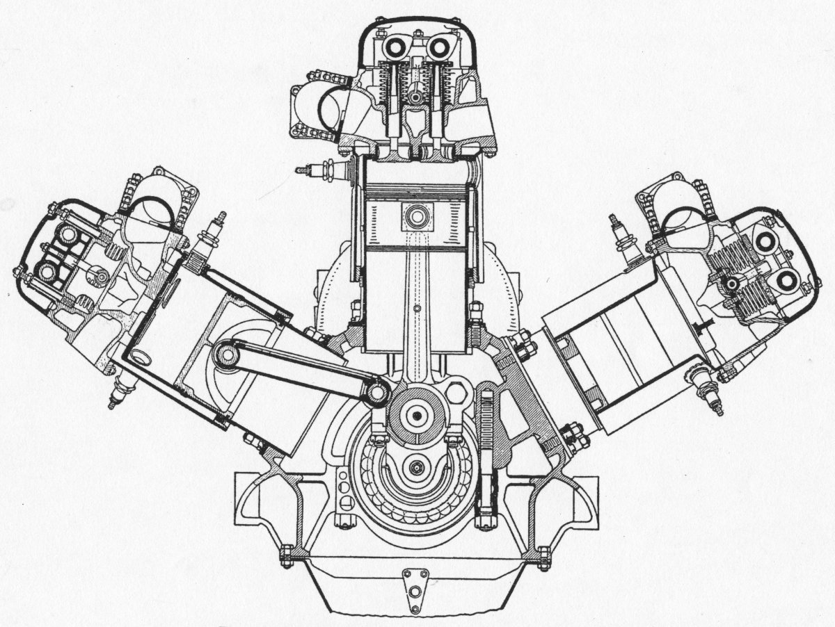 |
| Reciprocating gear used a central master rod with link rods at the sides. Shown is the manner in which the large roller main bearings were slid into place along the crankshaft, then made whole by insertion of a split collar at the crank journal. | An image and cross-section make clear the architecture of the Napier Lion. Dual ignition and duplicated coil valve springs were used for reliability. Crankcase and cylinder heads were cast of aluminium. | ||
The engine’s full-skirted aluminium pistons were exceptionally short in relation to the cylinder bores. Flat-topped, they were well ribbed under their crowns. Rings were four in number, with a triple pack at the top having two compression and one oil ring and a separate oil ring at the bottom of the skirt. ‘The compression ratio is 5.55:1,’ said The Automobile Engineer. ‘This is an exceedingly high figure. We do not know of any aircraft engines successfully running with so high a compression ratio, with the exception of the German Maybach engines. Such a compression ratio obviously shows to advantage when the engine is working in a reduced atmosphere. The pumping efficiency will be improved and consequently the m.e.p. and b.h.p. will be greater at high altitudes than would be the case if a lower compression ration were adopted.’
After the build and test of a small number—said to be two or three—of Mark I prototypes the final design of the E64 was settled as the Mark II. As requested by the Air Ministry, the Napier company’s initial concept was a high-compression engine, some 5.8:1, which would be run at part-throttle at ground level and at full power only at altitude. Before the engine was completed, however, the Ministry withdrew its constraint on low-altitude full-throttle operation. Fortunately, after some redesign the engine proved able to stand up to a relatively high compression at ground level—a boon to both power and fuel economy.
This was testimony to the unique construction method adopted with the E64’s Mark II version. Its cast-aluminium crankcase, extending well down below the crankshaft centreline, was enclosed by a pressed-aluminium sump with pickups at front and rear for the dry-sump oiling system. Along each side of the crankcase were three brackets for aeroplane installation.
 |
 |
 |
 |
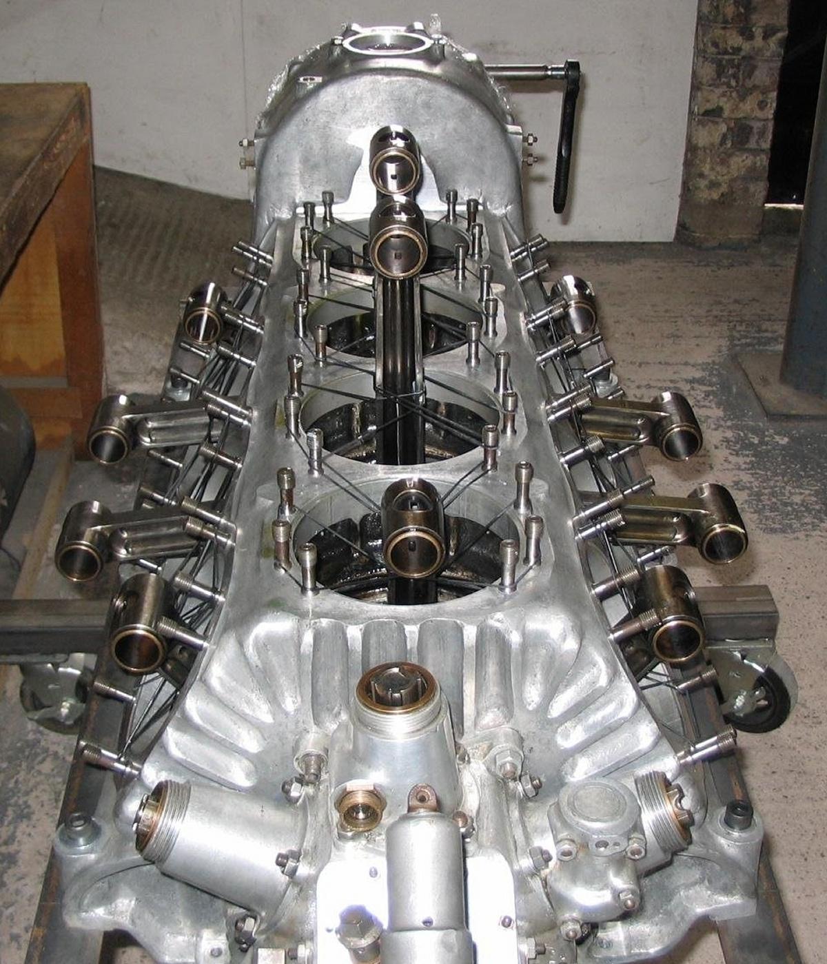
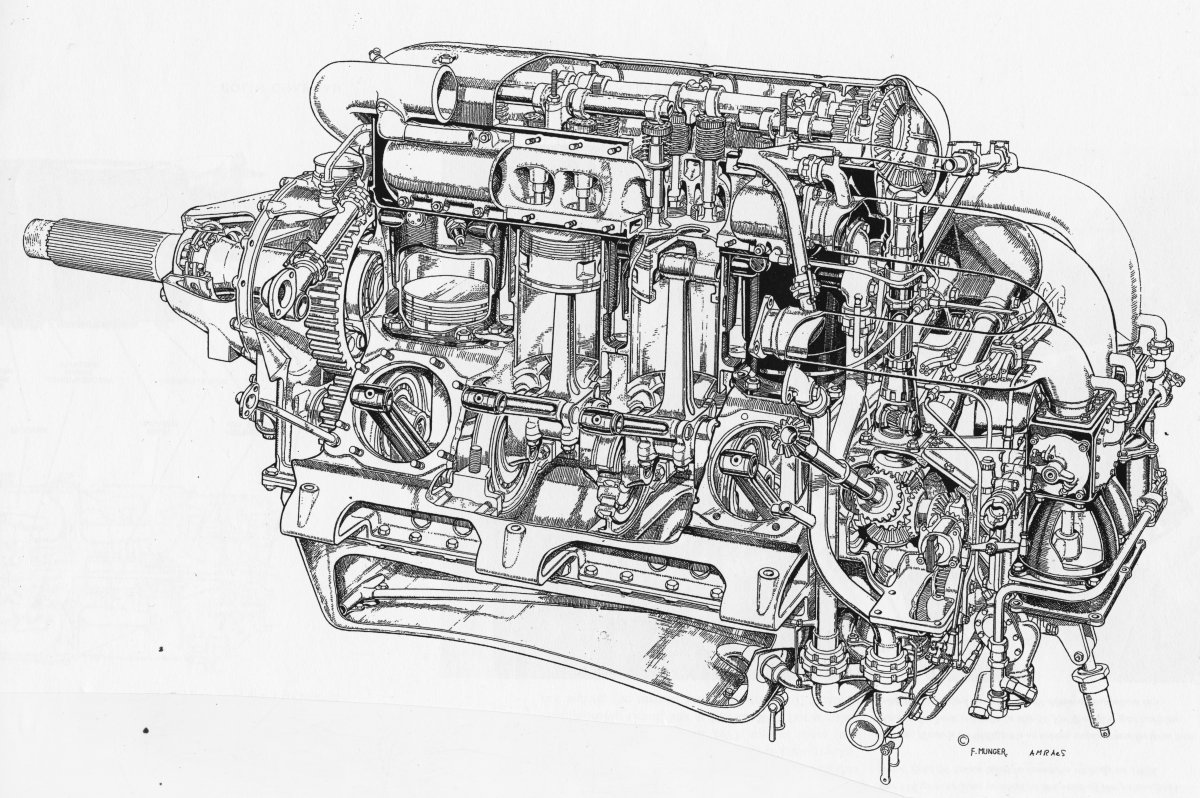
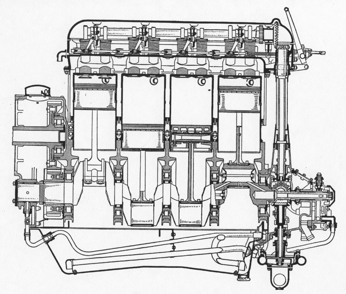
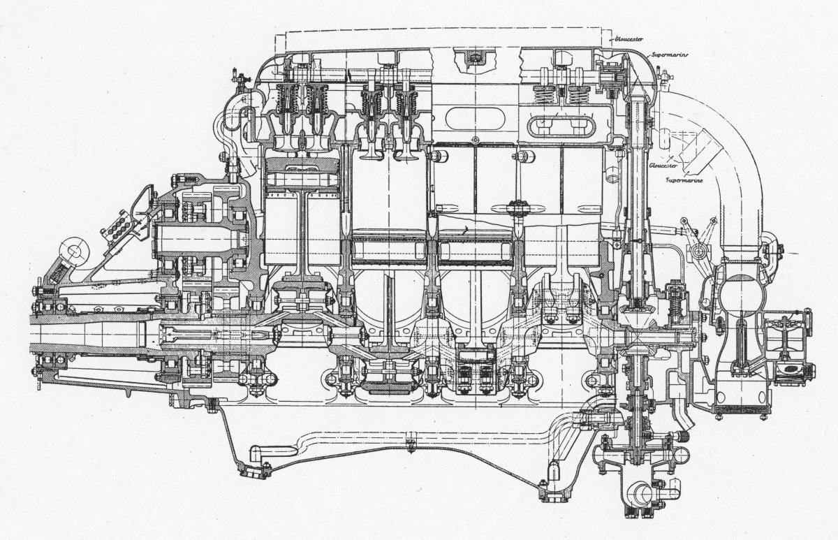
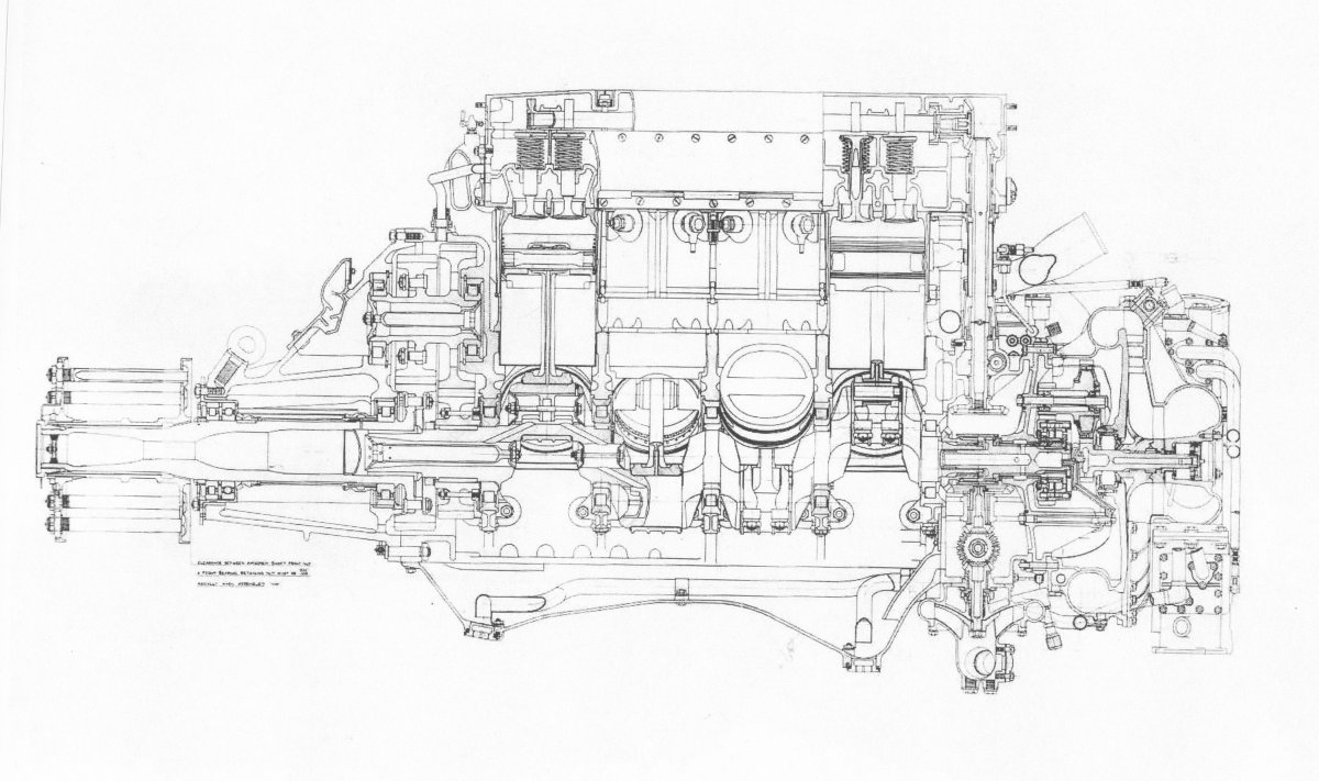
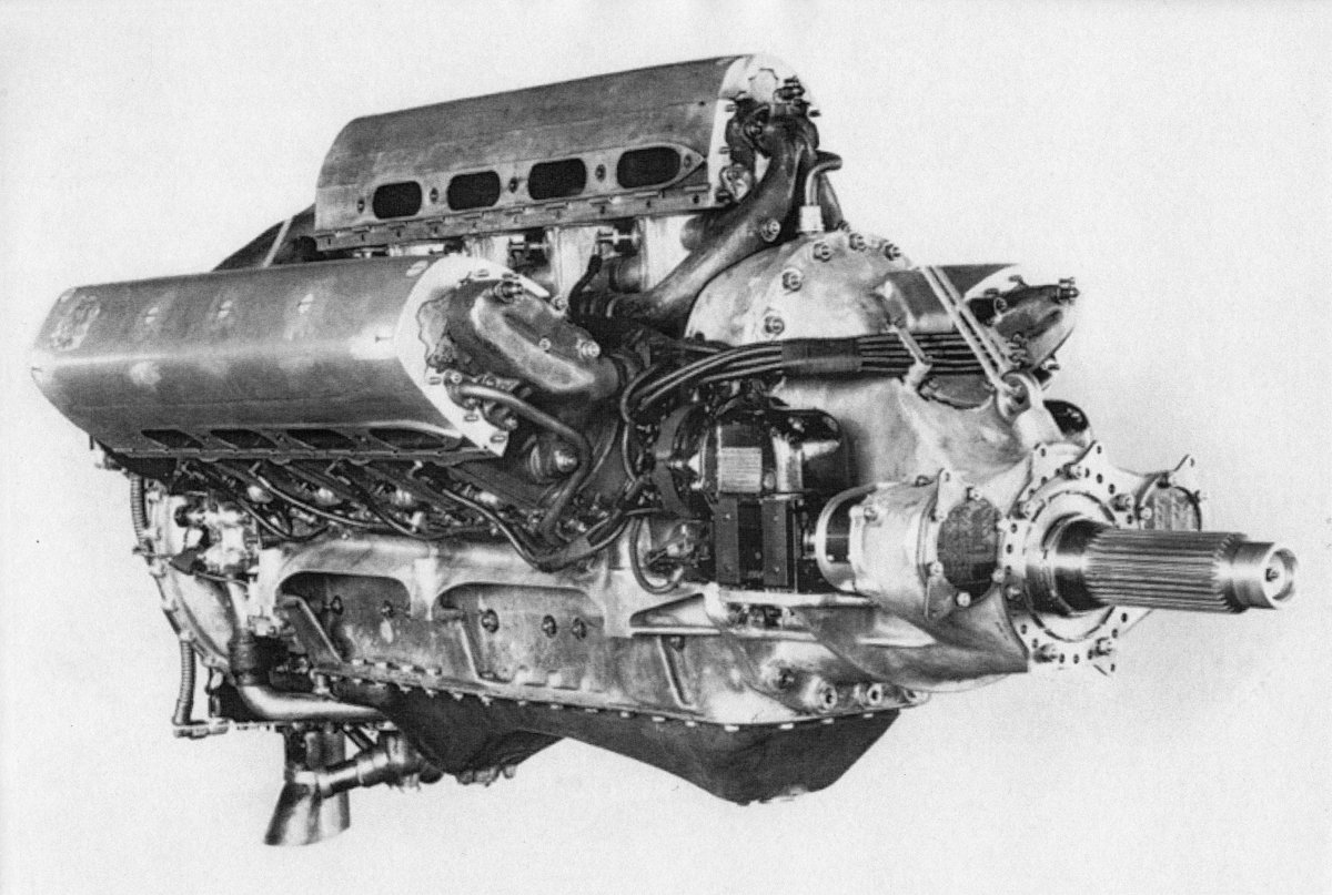
| Frank Munger’s cutaway of the Napier Lion W-12 showed a developed version much like that used in the Napier-Railton, with its carburettors at the rear. Drive gearing to the camshafts and accessories was all at the rear. | Strong support for the piston crowns was a feature of the Lion design. Lever at top right opened valves for easier initial staring process. | A longitudinal section of the Napier Lion shows its reduction gearing at left, removed for automobile use, roller main bearings and details of its lubrication system. | Shown in a Napier patent is the ingenious manner in which the four valve seats of each steel cylinder are screwed into the head to unite the two components. Extra cylinder-head cooling is provided for the exhaust port at left. |
Initially Napier and Rowledge proposed an aluminium block with steel liners to house all four cylinders in each bank. During early testing, however, such an engine ‘blew up’ on the dynamometer. Replacing the aluminium version was an all-steel fabrication that contained all four cylinders. Difficulty in ensuring water tightness led to a further change to individual cylinders in the final design. Machined all over, each forged-steel cylinder had a water jacket over its upper two-thirds. Fabricated from 28 pieces in all, each cylinder was meticulously welded by a team of women. Flanges at their bases anchored each bank of four cylinders to the crankcase by a total of 20 studs.
A perfectly flat top, forged integrally with each steel cylinder, had four apertures for two inlet valves and two exhausts. In an astonishing coup, these apertures were also the means of attaching the cylinders to the cast-aluminium cylinder head that topped all four cylinders on each bank. Its machined-flat face mated directly with the equally flat tops of the bank’s four steel cylinders, enough so to provide adequate heat transfer. Holding the two tightly together were threaded rings, screwed into the ports from the cylinder end, that also served as the valve seats. The rings were phosphor bronze for the inlet valves and steel for the exhausts. No water flowed between cylinders and heads, each having their own circulation system.
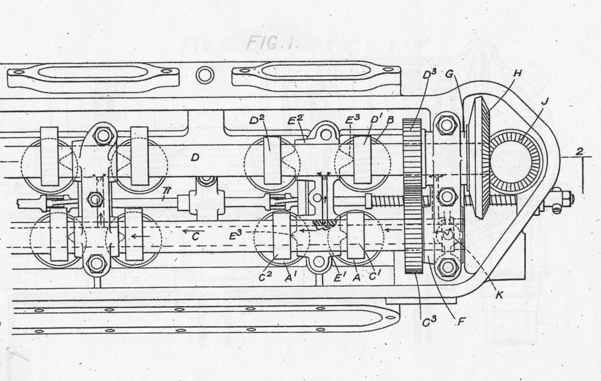
In the heads each cylinder’s four valves were vertical in phosphor bronze guides and closed by two coil springs apiece. Cam lobes directly attacked mushroom tops which screwed into hollow valve stems for adjustment akin to the manner of the Hispano-Suiza but with Napier’s own means of fixing the clearance. Although light and compact this placed lateral forces on the valve stems which eroded the guides. Care was taken to space the exhaust valves more generously than the inlets to allow more internal space for coolant.
Two close-spaced overhead camshafts opened the inlet and exhaust valves respectively in each head. Bearings supporting the camshafts were above the centre of each cylinder, between that cylinder’s paired valves. This assured the most rigid possible support for the cam/valve interaction. [In the late 20th century this placement of the camshaft support bearings between the valves in a four-valve cylinder head was revived as a hallmark of the best design for automobile racing engines.] As well it positioned the bearing support where it could consistently and accurately deliver an overflow of its lubricant to the tops of the adjoining four tappets, a feature which Napier patented.
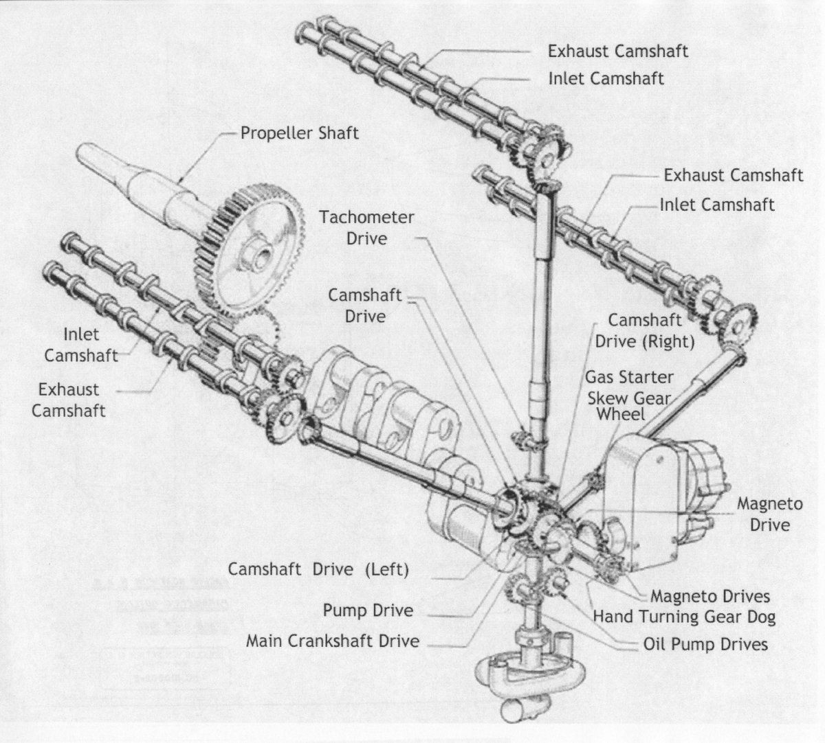
Drive to the camshafts was at the rear of the engine by shafts and bevel gears. The arrangement of the three shafts and their drive from the crankshaft, as well as other accessories driven from the same point, underwent substantial change during development from the Mark I prototype.
In the first Napier/Rowledge design the necessary half-speed reduction was at the bevel gear from the crankshaft to the shaft that went vertically to the exhaust cam of the central bank. Driven from bevels on that central shaft were the shafts that went to the inlet camshafts of the outer banks. The next iteration brought a substantial change in the drive, although still with the half-speed reduction at the crank nose. Now the two shafts to the outer banks went to the exhaust camshafts. The central shaft was driven by a bevel from the right-hand shaft and also turned the middle bank’s exhaust camshaft.
In the third and final iteration of the E64’s cam drive the reduction to half engine speed was at the top pairs of bevels, with 14 teeth driving 28. This had the benefit that the shafts turned at twice the speed but carried half the torque and thus could be smaller in diameter and lighter. A small and manageable penalty was a bulge in each camshaft cover to accommodate the necessarily larger driven cam gear. While the central shaft drove the inlet camshaft the two outer shafts drove their respective exhaust cams. A pair of spur gears took the drive to each sister camshaft.
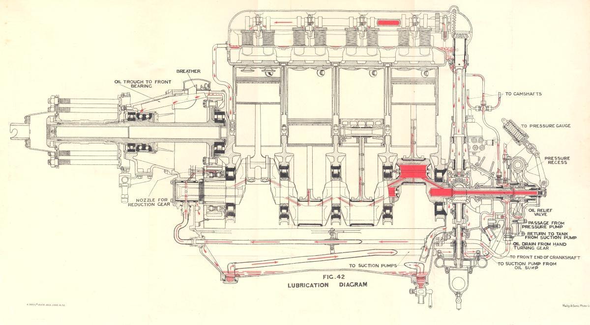
In the accessory chest at the E64’s anti-drive end a bevel gear turned a shaft downward which drove a water pump at engine speed, delivering through a separate outlet to each bank. From a skew gear two shafts turned three oil pumps at half crankshaft speed, one for pressure and two to scavenge the front and rear of the sump. Oil drawn from a reservoir was pumped through oil galleries in the crankshaft and then directed by drillings to lubricate the big ends and the articulated rod bearings. An extension of the crank nose drove two 12-cylinder British Thomson-Houston magnetos to the left and right. KLG sparking plugs were on opposite sides of each cylinder, opening onto the combustion chamber.
‘The first instinct is to criticise the whole distribution gear as being excessively complicated,’ opined The Automobile Engineer, ‘but when the number of units to be actuated are considered there does not seem to be much room for any serious simplification of the scheme. When it is remembered that, including the six camshafts, there are no fewer than thirteen parts being driven from the distribution gear, we think that the designers are probably to be congratulated on the comparative simplicity of the distribution mechanism.’
 |
 |
 |
.jpg) |
 |
| Visible in the assembly of a Lion W-12 are the bevel gears of its camshaft drive and the spur gears between the cams. One of the long tapering inlet-manifold covers is shown on the nearest cylinder bank. | The wider spacing of the exhaust valves to make better internal provision for cooling is evident in the Napier patent covering the manner in which runoff oil from the camshaft bearings is directed to the cam lobes and followers. The camshaft drive, right, underwent major changes during the engine’s development. | Views of a cutaway and part-assembled Lion give a good sense of its unique construction. Twin magnetos are driven by cross-shafts at the rear of the W-12. | ||
Serving each bank of four cylinders was its own carburettor throat in instruments mounted at the front of the engine. Early engines used Claudel-Hobson HC7 carburettors, a single on the right and a duplex on the left to serve two inlet manifolds on that side. Their delivery pipes to the manifolds were water-jacketed to ward off icing at altitude. Effective with the engines used in the racing Gloster II in 1924 and then the Series VII introduced in 1925, a direct-drive version intended for racing, Lions had their carburettors moved to the rear. This helped designers create more penetrative nacelles.
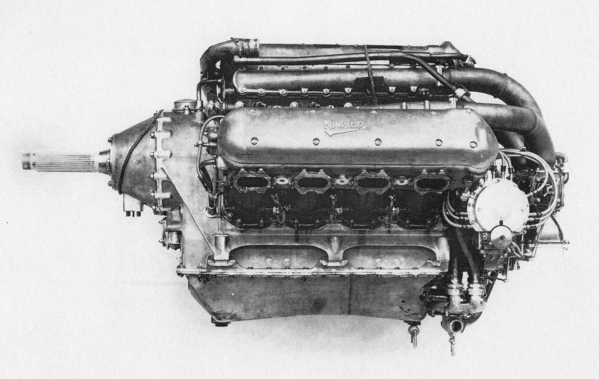
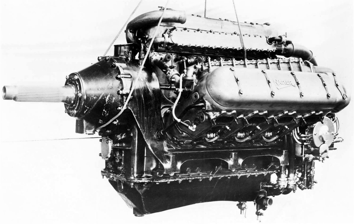
Among many of its contemporaries, still festooned with exposed pushrods, rockers and valve springs, Napier’s E64 was a notably clean-looking power plant with its curved camshaft covers and tapering inlet manifolds. It was dated-looking only in its exposed individual cylinders, which in view of their exceptional contributions to the engine’s lightness and robustness were fully excusable. An early engine scaled 838 pounds and fit into a cube 50 inches long, 42 inches wide and 36 inches high.
Its design being completed in 1917, development of the ‘Triple-Four’ commenced in that year with the result that 35 of the 100 engines ordered could be delivered. After type testing of the Series II version was completed, its aeronautical trials commenced on 16 February 1918. Its flying test bed was an Airco D.H.9 two-seat biplane designed by Geoffrey de Havilland and produced by the Aircraft Manufacturing Company, Ltd., known as Airco. These trials led to the entry into service with the Royal Air Force of the first ‘Napier Aeromotor’ on 4 October 1918. Thus it and a handful of sisters were too late to be of use in the conflict, which ended the following month.
‘It was only as news of the power and reliability of this compact and advanced twelve-cylinder “W” layout engine quickly spread through the RAF,’ wrote Napier historian Alan Vessey, ‘that their pilots and Air Staff adopted the emotive name “Lion” for the new power unit from 1920 onwards. [An article in The Automobile Engineer describing the new engine in its issue of August 1919 identified the engine as the Lion.] Could that name have been coined from its more aggressive power in the air with the exhaust’s low growl, via twenty-four exhaust valves exiting into three exhaust manifolds, these opening out to four stubs for each cylinder bank? Or perhaps to pilots in their single-engine aircraft cockpits the high centre cylinder bank's rounded DOHC cover and stub exhausts could, at times, resemble the “long hairy mane” of a lion's head and shoulders, as it dominated their forward view?’
Early in 1920 engineers at McCook Field, Ohio prised open a crate containing a Series II Lion with a 5.53:1 compression ratio. They soon had it on a test stand, where they found it required fuel of a higher standard than straight aviation petrol. Adding 20 per cent benzol to the mix—a ratio normally used in its home country—allowed full-power running without preignition. Their W-12 developed 500 bhp at 1,350 rpm of the propeller shaft, equal to 2,050 crankshaft rpm. The flat torque curve showed 1,335 lb-ft at 1,730 crank rpm. The American experts summarised their findings as follows:
Design
The 450-horsepower British Napier Lion is compact and very light for the horsepower developed. The over-all length is small for an engine of the output obtained. The crankshaft and connecting-rod assembly are well worked out. The use of a reduction gear permits of low and efficient propeller speeds.
Performance on Test
The engine showed a high output per unit of piston displacement. The BMEP was very high and maintained fairly well throughout the speed range, indicating
good volumetric efficiency. The high bore-stroke ratio and the large valve area, in proportion to displacement, probably account for the high volumetric efficiency. The fuel consumption was low, especially on the propeller load runs. There appeared to be little vibration, but accurate observations on this point were impossible due to the rigid dynamometer mounting. [Elsewhere in the report they stated that ‘The engine ran with marked freedom from vibration through the speed range of the test.’]
Accessibility
The parts of the engine are fairly accessible. The carburetors are well located and can be reached through doors in the cowling of the fuselage. The magnetos are set transversely across the rear of the engine and can be reached by side doors in the cowling. The oil pressure relief valve and oil filter are readily removed for inspection. The spark plugs are readily accessible. The whole auxiliary gear train at the rear of the engine can be removed as a unit.
Adaptability to Airplane Installation
The general arrangement of the engine has resulted in a concentration of masses close to the center of gravity and a short overall length which make it well adapted to airplane installation.
Adaptability to Production
The 450-horsepower Napier Lion would not be well adapted to American production methods. There is a multiplicity of small parts and few of the major parts are interchangeable on the same engine. Three separate cylinder block and induction units are used on each engine, none of which are interchangeable. Considerable handwork is involved in the construction and assembly of the engine.
Conclusions
The performance of this engine was good. While it is not recommended as a service type because of the unnecessarily complicated construction, the general arrangement and some of the parts such as the valve gear, crankshaft bearings, compression release etc. might well be studied in connection with proposed engine designs.
It seemed to elude the McCook Field evaluators that the Lion’s all-round exemplary performance for its size and weight might be related to the design features that they considered ‘unnecessary’. To be sure, American engine builders aimed not to have major components that required squads of female welders to execute. Perhaps surprisingly none of them took up the recommendation to consider using the engine’s highly praised ‘general arrangement’.
In the 1920s other makers of large engines would follow Napier’s lead, especially Farman and Lorraine-Dietrich in France, some of these with 18 instead of 12 cylinders, but none was destined to have the all-around excellence, versatility and longevity that characterised the Napier Lion. Destined for greatness in the air, on land and on water, it elbowed Napier’s auto production aside. By 1924 about half of all British aircraft were powered by the Lion W-12 while Napier automobile production had ceased. Although a post-war car was mooted, at a Cannes meeting in 1919 Montague Napier committed the company to going forward without cars.
‘In its time,’ wrote Leonard Setright, ‘the Lion was enormously successful, dominating the market for water-cooled engines, especially for long-range duties. Until 1926 it was used in almost all new commercial transport aircraft in Britain and several European air forces employed it as well. In the entire British Empire, upon which in those days the sun shone as unceasingly as it had once done on the Spanish empire of Philip V, the Lion was pretty well the only powerplant used for long-range military aircraft in general and flying boats in particular.’
The Lion burst onto the stage with an achievement considered ‘sensational’ at the time by Flight, which headlined its story on the achievement with ‘nearly six miles high’. The aeroplane was an Airco D.H.9 as used for the engine’s first trials. Powered by a Series II Lion, it essayed an altitude test on 2 January 1919 from Martlesham Field in Suffolk in the hands of Captain Lang and Lieutenant Blowes of the RAF.
After only 6⅓ minutes the Airco-Napier had reached 10,000 feet. In 19⅔ minutes from takeoff it was at 20,000 feet. An oxygen-supply failure benumbed observer Blowes but, unaware of this, in a total of 66 minutes pilot Lang continued to 30,500 feet ‘when the engine stopped owing to the pumps failing to maintain sufficient pressure in the petrol tank,’ said Flight. Blowes recovered his senses at 20,000 feet on the way down. Frostbite on hands, face and toes was a consequence for both men. Although not observed and ratified, this was 1,600 feet higher than an American effort the previous year and a stunning 10,000 feet higher than the existing official record altitude.
Soon in full production at Acton, Napier’s Series II Lion was its mainstay in the early 1920s, chosen to power a plethora of Airco, de Havilland, Fairey and Vickers aircraft among others. With a compression ratio of 5.8:1, the mainstream Napier Lion Series IIA of 1926 developed 470 bhp at its normal maximum speed of 2,000 rpm. At its peak permissible speed of 2,200 rpm it was rated at 502 bhp. Its spur reduction gear ratio of 0.659:1 gave a propeller speed at normal rpm of 1,318 rpm. Consuming 245 pints of fuel per hour, this was an economical as well as powerful engine suited to applications that would ultimately number 130 types of aircraft.
‘Montague Napier’s plan was having its designed effect,’ said Wilson and Reader: ‘as the car business tailed off, aero engines were becoming the sole stock-in-trade and the Air Ministry was coming more and more to take its appointed place as overwhelmingly the most important customer. Civil flying, it is true, was developing, and the great commercial airlines were taking shape, but they were subsidised by the Government with an eye to defence and the demand from them was hardly an independent source of business.
‘All the engines which the company made under this system,’ added the Napier historians, ‘were at first on the Secret List, and even when they came off it the Air Ministry had absolute power in practice, if not in law, to forbid sales to anyone except itself. Napiers would not, of course, attempt to sell an engine to anyone else while it was still on the Secret List and by the time it came off it would probably be rather old-fashioned. This by itself goes far to explain why the export trade in the ‘twenties was not a major source of business, though it was by no means neglected.’
 |
 |
 |
 |
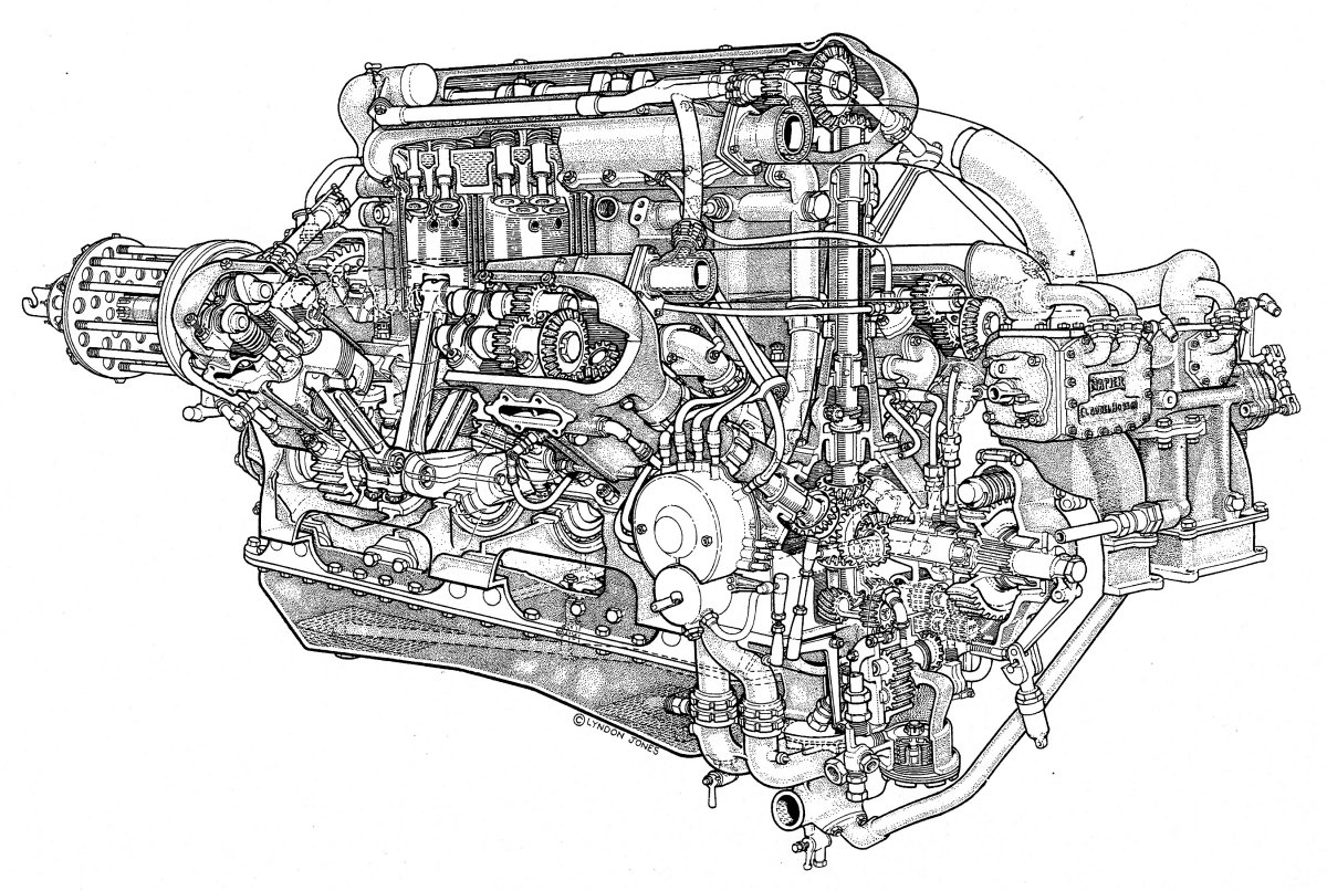 |
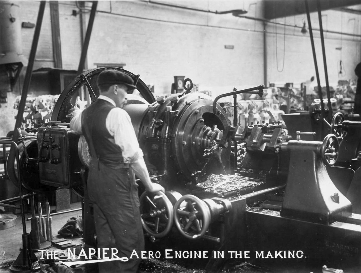
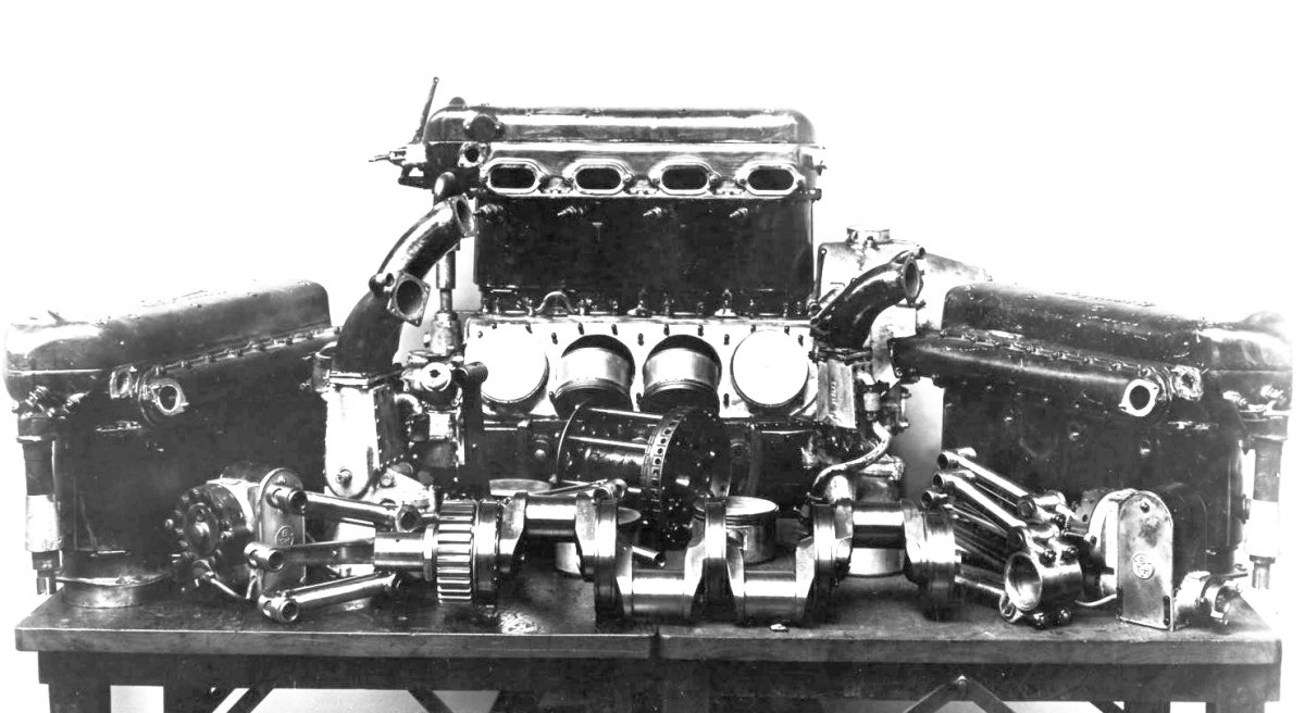
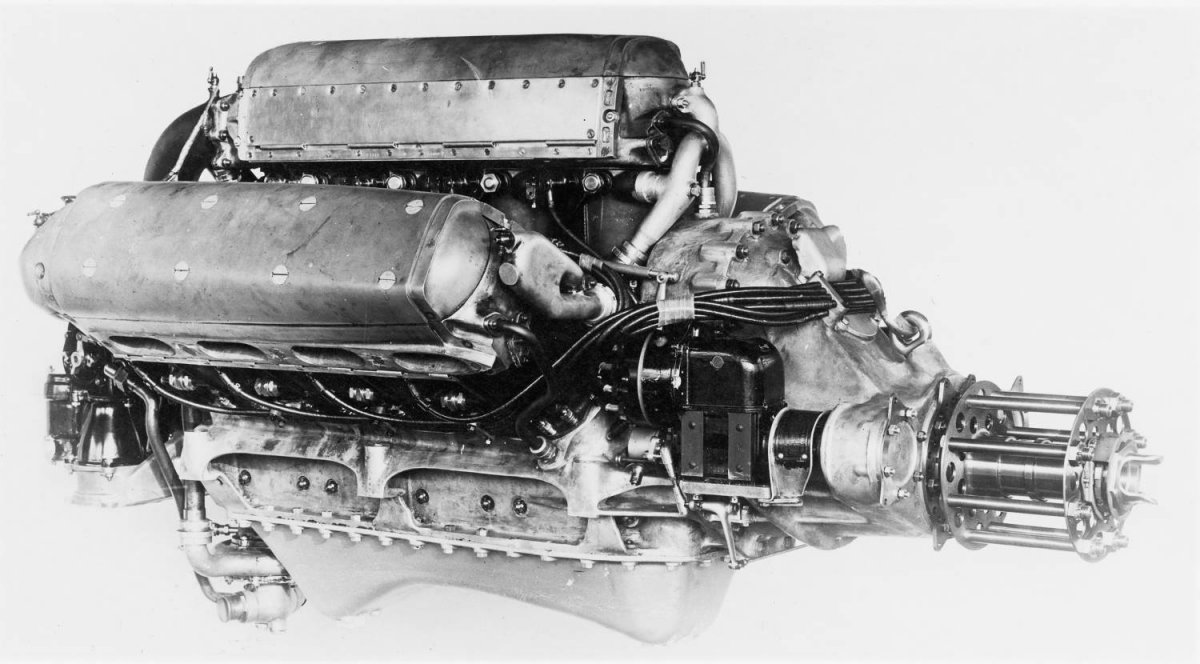
| In its earliest configuration the Napier Lion had its carburettors at the front, using a twin-throat unit on the left and single throat on the right. The needs of nacelle design for racing resulted in their move to the rear in 1924-25. | With justifiable pride Napier published a series of images showing steps in the production of their unique engine. Here a lathe operator is machining a crankshaft. | Also shown in Napier’s picturing of Lion production was a display of the W-12 engine’s components. | Independent confirmation of the attributes of the Napier Lion came from the test of an engine conducted by American experts at Dayton, Ohio’s McCook field. This was their graph of the output of a Series II W-12. | A cutaway by Lyndon Jones depicts the Napier Lion XI, featuring its complex gear trains to the overhead camshafts and accessories. |
One reason why HM Government wished to keep a leash on its Napier Lions was that these engines were Britain’s best bet in the contests for the trophy presented in 1912 by Parisian Jacques Schneider to be won by the fastest seaplane, a type of aeroplane whose development he wished to foster. In the event it would be fought for by entries from Italy, the United States, France and Great Britain.
Britain’s Lion-powered entry in 1922 was a small biplane that looked cumbersome but was touched by the magic of Reginald Joseph Mitchell, who had been hired by Hubert Scott-Paine, chief of its builder Supermarine, in 1920. Named Sea Lion II, with its Napier engine in a pusher configuration, she was piloted by the company’s test pilot Henri Biard in the contest held above the sea off Naples, for the previous winner was Italian. Against tough opposition Biard regained the Schneider Trophy for Britain at a speed of 145.7 mph.
Revised as Sea Lion III with power boosted to 550 bhp, the Supermarine craft was flown again by Biard at Cowes in 1923 but had to give way to a Curtiss-powered American assault on the Schneider race. In 1924 the Americans cancelled the race when their only challengers, Lion-powered Gloster II biplanes, were unready.
For 1925 the Air Ministry ordered two contenders, one from Gloster and the other from Supermarine, both Napier-powered. This was the first outing for the Series VII Lion, a radically reworked W-12. Connecting rods and cylinders shorter by one inch allowed the heights of its three banks to be reduced, with other changes, by 1½ inches to lessen its frontal area. Made of Y-alloy aluminium, its pistons were also shortened. Its crankcase was magnesium instead of aluminium, with cross-bolting of the main-bearing caps by double bolts at both sides. Raising the compression ratio to 8.0:1 required the addition of 25 per cent benzol to the petrol fuel plus the addition of 13 cc of tetra-ethyl lead per gallon to bring its output to 680 bhp.
While the Americans had won in 1923 with biplanes, R. J. Mitchell decided on a mid-fuselage monoplane configuration for his Supermarine S.4. With its cockpit well to the rear visibility was ‘perfectly dreadful’, said pilot Biard. On 13 September, however, he was officially timed at 226.75 mph at Calshot, Southampton. This was a new absolute world speed record for seaplanes. Readying for the race over Chesapeake Bay, however, Biard lost control of the S.4—which he admitted frightened him—and survived the resulting crash into the Bay. Damage on rough water kept the Gloster-Napier entry from competing.
Although controversial at the highest levels in Whitehall, Government support of the development of these high-speed aeroplanes continued to be justified by advancement of the state of the art and by promotion of the products of Britain’s airmen. However any chance of a UK entry in 1926 fell foul of political to-ing and fro-ing with the result that it was America versus Italy at Hampton Roads with Italy’s low-wing monoplanes prevailing. ‘Your orders to win at all costs,’ cabled Mussolini, ‘have been carried out.’
To be tested and raced by pilots from the RAF’s new High Speed Flight, three British rivals for the Fiat-powered Italian entries were built for 1927, two of them with Series VIIA Lions. Napier’s Type E86, these built on 1926’s improvements plus a further increase in the compression ratio to an unprecedented 10.0:1. Coping with this was light Romanian petrol salted with 7 cc per gallon of tetra-ethyl lead. The result was 898 bhp at 3,300 rpm for an engine weighing 928 pounds dry.
‘Almost as important to engineers,’ said fuel expert F. R. ‘Rod’ Banks, ‘this engine was subjected to an officially observed test, with Ricardo as official observer, and recorded a specific fuel consumption of 0.32 pounds/bhp/hour—practically the theoretical possible for that compression ratio.’ ‘The Lion then boasted the most extraordinarily high thermal efficiency,’ wrote Leonard Setright in 1971: ‘its specific fuel consumption of 0.32 lb/hp/h was not only far and away better than anything that had ever been known before but has possibly not been equalled and certainly never been bettered since.’
The first Series VIIA Lions were built with direct drive, but the possibility that a reduction gear would be useful led to the novel design for the VIIB, Napier Type E90, of a two-stage ‘coaxial’ reduction that left the propeller in the same position. Both versions had all-new cylinder heads with smoothly machined exteriors and main castings that completely integrated the inlet manifolding, into which the fresh charge was ducted from the rear. Cast open, the inlet passage was closed by an aluminium plate with multiple screw fixings.
With this new Lion version Supermarine’s R. J. Mitchell could continue the established practise of giving each of the engine’s three banks its own individual streamlined fairing behind the propeller. In fact he could and did go so far as to use the three smooth camshaft covers as the exterior surface of the aeroplane. The cylinders in the centre bank of the Series VIIA and VIIB Lions exhausted to the left and received their fresh charge from the right. The twin magnetos were now mounted at the front.
Both versions of the much-changed engine were prepared for the 1927 race on the coast of Venice, where only the British challenged the Italians. ‘This was the high-compression Lion,’ said Leonard Setright, ‘with a specific weight of 1.06 pounds per horsepower, which was in itself inferior to that of the Fiat, but because of the extraordinarily high thermal efficiency of the Napier engine the combined weight of engine and fuel for the race would actually be less for the Napier than for the admittedly more powerful Fiat engine.’
R. J. Mitchell’s Supermarine S.5 was a low-wing monoplane pared to such slenderness that its right-hand float had to be used to carry fuel. Two S.5-Lions were entered, with Flt. Lt. Worsley taking the direct-drive engine and Flt. Lt. Webster the Series VIIB, which had a reinforced crankshaft.
On a very fast course Napier-propelled Sidney Webster was the 1927 Schneider Trophy winner at a speed of 281.65 mph while Worsley was second at 273.01 mph. Webster’s best timing of 284.21 mph was (unofficially) a new world air-speed record. One Italian complained of his Fiat engines that ‘that wasn’t horsepower. It was donkey-power.’
‘A considerable amount of the success of the British entry was due to the Napier Lion engine,’ wrote Ellison Hawks in his history of the Schneider races. ‘The standard Napier engine in the 1925 Schneider Trophy machines developed 700 h.p. but the special engine of the 1927 contest developed nearly 1,000 h.p. The amazing power developed by this comparatively small engine was regarded as a mystery, the output obtained from an engine of such compact size (3 ft. x 6 ft.) being unique at that time—nearly 900 h.p. for a fraction over 1 lb. weight per h.p.’
 |
 |
 |
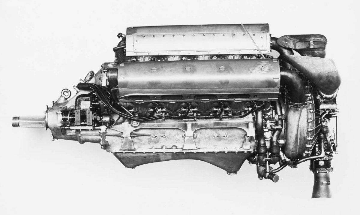
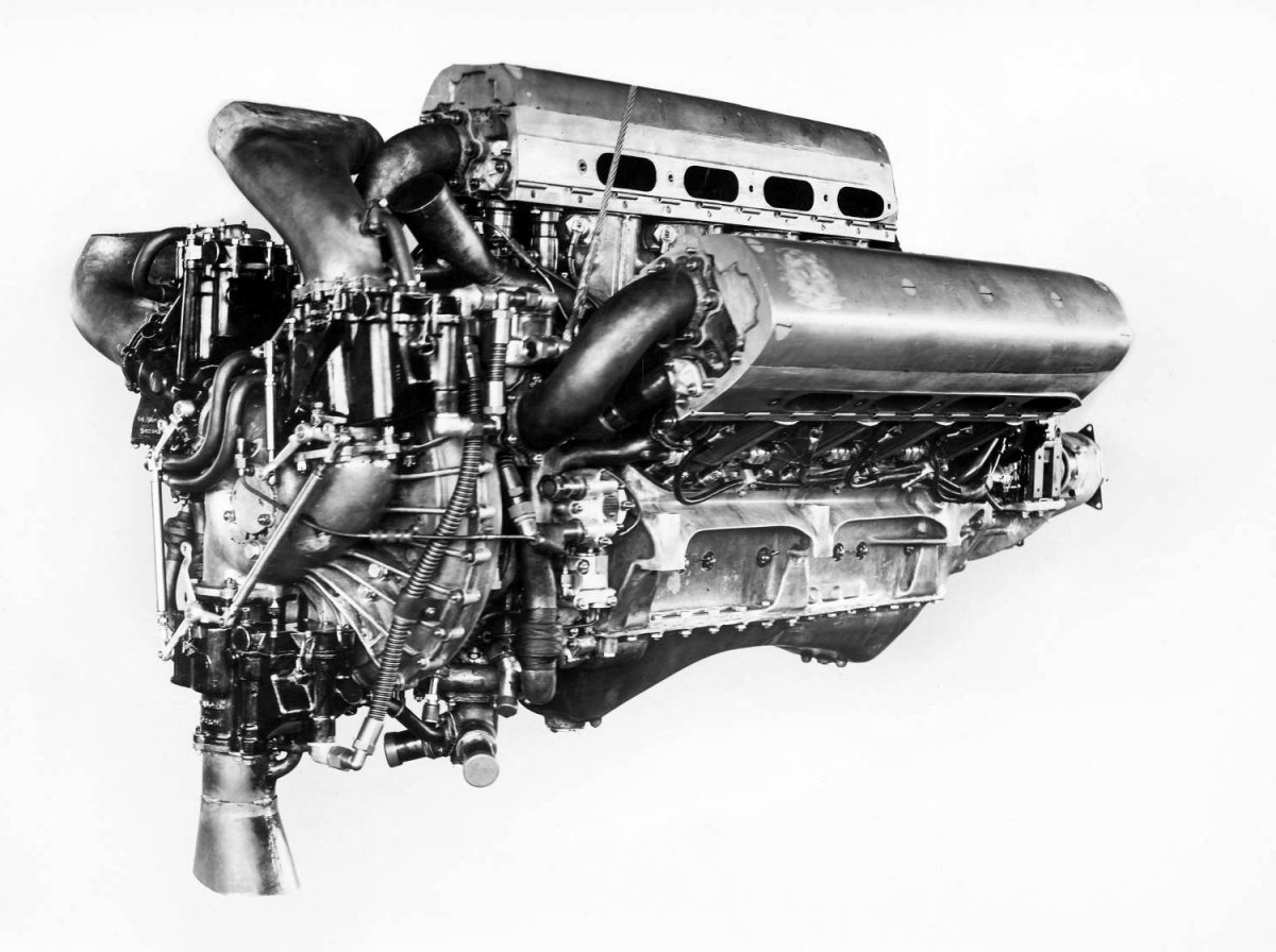
| Side and rear views picture the Napier Series XIA Lion as used in John Cobb’s Napier-Railton. In the car the carburettors were forward and the reduction gear removed to provide a direct drive. | ||
 |
 |
 |
| Sections of the Lion Series VIIB show its reduced stroke and shorter connecting rods for higher revs and smaller frontal area. With a two-stage reduction gear it brought the propeller back in line with the crankshaft. In VIIA direct-drive form an engine of this type was used by Malcolm Campbell for his Blue Bird in 1928. | Specifically for Schneider-Trophy racing Napier introduced its radically redesigned Series VII Lion in 1925. Visible in its magnesium crankcase were the double bolts retaining the main-bearing caps. Camshaft-cover design was entirely new and magnetos were now tucked in at the front. | |
Perhaps spurred by their failure, the Italians made great progress in engines before the next Schneider contest in 1929, the series having gone biennial. One of their craft set a new air-speed record of 318.64 mph in 1928. Accordingly the British readied a second string for their bow in the form of a supercharged Rolls-Royce V-12 in which ex-Napier man Rowledge had a major hand. Not to be denied, Montague Napier authorised work on a supercharged version of his Lion. Directed by George Shakespeare Wilkinson and assisted by Henry Christopher Tryon, the Series VIID effort benefited from the addition to the Acton team of Alfred John Penn, an expert compressor designer.
From the tail of the Lion’s crankshaft the engineers drove a single-entry centrifugal blower whose impeller was 11 inches in diameter. Including a cushioning element in its first stage, its drive used two gearing stages to bring the blower up to the high speed needed to produce effective boost. Mixture feed to the charger was from three Claudel-Hobson carburettors feeding into the impeller’s entry at 120-degree spacing. Around the top of the torus into which the compressor exhausted were three takeoffs to the respective cylinder banks. Using a different version of the newly designed cylinder heads, on the centre bank the inlet was to the left and exhaust to the right.
The knowledgeable Alfred Pett kept the moderate compression ratio of 6.0:1 for this supercharged version of the Lion. [Many accounts state that this engine, like the unblown Series VII racing engines, had a 10.0:1 compression ratio. This would have been much too high for the efficient operation of a supercharged engine.] Its blower took the W-12 to unprecedented power and speed. At 3,000 rpm it produced 1,100 bhp, at 3,400 rpm 1,240 and at just over 3,600 rpm 1,320 horsepower. Its 0.694:1 reduction gear lowered these high revolutions to rates better suited to propellers. It fitted snugly into the Gloster VI designed by Henry Philipp Folland, who adopted a sleek low-wing monoplane configuration for the first time.
Smaller and lighter than the Rolls-powered Supermarine entries, the two Gloster-Napiers were the preferred aeroplanes of Flt. Lt. G. H. Stainforth, a member of the chosen pilot crew in the charge of Squadron Leader Harry Orlebar. However persistent fuel-system faults defied all efforts to keep their engines from popping and banging erratically. Both were withdrawn the night before the race, leaving Stainforth without a mount. Nor had entries from France and America made it to the starting line. Although very fast the Italians faded in the contest with the victory going to Fg. Off. H. R. Waghorn in the Rolls-powered Supermarine S.6.
Although Napier did not participate in the 1931 race for Schneider honours, its 1927 win made it three in a row when a Rolls-Royce-powered Supermarine entry triumphed again. According to the terms of Jacques Schneider’s gift this entitled the English to permanent possession of his marble-mounted silver and bronze trophy. At first held by London’s Royal Aero Club, the trophy later rested in its Science Museum. In 1931, as well, Montague Napier breathed his last.
The Napier company had not overlooked more mundane demonstrations of the attributes of its unique W-12 Lion, which continued to enjoy commercial success. From 1925 to 1928 the standard Lion was the Series V. It was sold for general use with a 5.0:1 compression ratio, giving a maximum 458 bhp at 2,200 rpm, and for military applications with 5.8:1 compression to produce 502 bhp at 2,200 rpm.
In 1928 Napier updated its standard Lion range with the Series XI, which had rear-mounted carburettors and induction on the left and exhausts on the right of its central cylinder bank. Fuel economy benefited from a compression ratio raised to 6.25:1 as did propeller efficiency from a 0.531:1 reduction gear. At 2,585 rpm it had takeoff power of 570 bhp while at a cruising 2,350 rpm output was 530 bhp.
Series XI Lions powered the four RAF-staffed Fairey aircraft that completed the first formation flight from Cairo to Cape Town and back to England in 1926, making stops along the way. This pioneering flight covered 56,000 engine miles without trouble and was successfully repeated during the four following years with Lion-engined Fairey aircraft. In 1928 four Supermarine Southampton flying boats, each fitted with two Lion engines, flew from England to Australia, around Australia and back to Singapore, covering 180,800 engine miles without mechanical trouble.
In its Series XIA version, Napier’s Type E92 was the engine of choice for Fairey’s advanced Long-range Monoplane, known as the LRM, built in 1928 with the express aim of setting new world distance records. Although carrying only two pilots, one flying and one resting, it was a big monoplane with an 82-foot span of high wings that contained gravity-feed fuel tanks holding 1,157 gallons.
A first attempt in 1929 was a terminal failure, striking high ground in Tunisia. After proving flights in 1931 and ’32 a second Fairey-Napier LRM set a new distance record in February of 1933. In 57 hours and 25 minutes it flew from Cranwell, England to Walvis Bay in what is now Namibia, a distance of 5,309 miles and a 429-mile advance on the previous record. A check of its tanks at Walvis Bay found less than 10 gallons. Since the flight’s goal was Cape Town, seven hours further south, the navigation confusion that led them to put down at Walvis Bay was fortuitous.
 |
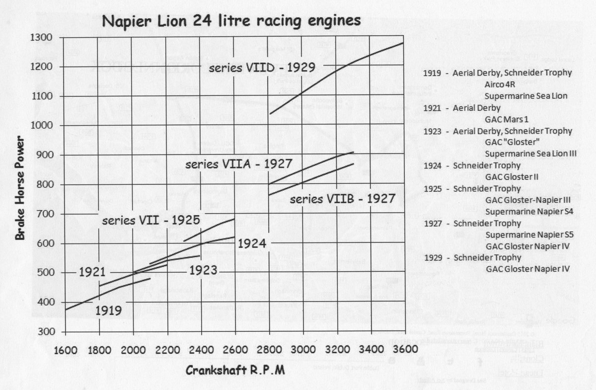 |
 |
 |
| Britain was successful in the 1927 Schneider Trophy race at Venice with the Supermarine S.5 powered by a Lion Series VIIB. The aircraft’s designer, R. J. Mitchell, was at the centre in blazer and white trousers. At top was the winning pilot Flt. Lt. Sidney Webster. | A chart showed the progression of Napier Lion engine power, the racing versions starting at 2,800 rpm and going upward. Only the Series VIID was supercharged. | Prepared for the 1929 Schneider Trophy races but in the event not used, the supercharged Series VIID Lion approached 1,300 bhp at 3,600 rpm. The unit pictured had Napier’s compact ‘coaxial’ reduction gear. The seven engines built were destined for more success in cars and boats than in aeroplanes. | |
 |
 |
 |
 |
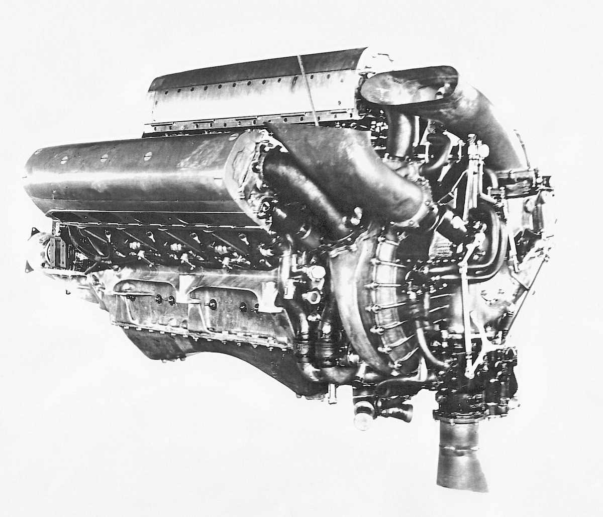
| Frontal views of the Series VIID Napier Lion showed its remarkably compact reduction gear and one of its twin magnetos. With direct drive these engine were revved as high as 4,000 rpm by ground-borne record breakers. | At the rear — the front in most car installations — the Series VIID Lion carried its 11-inch centrifugal supercharger fed by three Claudel-Hobson carburettors. Outlets from the blower led to inlet manifolding made integral with the new cylinder heads. | The beautiful Lion-engined Gloster VI seaplane was the winner of the 1929 Schneider Trophy races. | |
Inevitably record-breakers in other spheres paid respectful attention to the potentialities of this new engine. The first to cadge a racing Lion from the Admiralty was Malcolm Campbell, who employed it to set a new world land-speed record with his Blue Bird I on 4 February 1927 at 174.88 mph. In 1928 Campbell’s car underwent revisions to accommodate a Series VIIA Lion with its higher compression and 898 bhp at 3,300 rpm. At the same time a similar engine was made available to Jack Irving for the car he was building for Sir Henry Segrave, the Golden Arrow. Like Campbell’s it could be taken to 3,600 rpm for short periods.
Both men made good use of their Lions, Segrave rather more than Campbell. In March of 1929 Segrave set a new land-speed record when he drove his Lion-engined car over a mile at 231.45 mph at Daytona Beach. Denied the outright record at Verneuk Pan in South Africa, Campbell set up world land-speed records over five miles at 211 mph and over five kilometres at 216.53 mph with his Blue Bird II. The era of the Lion as an important engine for attacks on speed on land had arrived.
In the same year the Lion made its debut in marine record-breaking service. At Miami, Florida the world’s motorboat speed championship was won by Segrave in 1929, driving Lord Wakefield’s Napier-engined Miss England I. With this same craft six runs were made over a measured mile at the Venice Lido at an average speed of 91.91 mph, making it the world’s fastest single-engined boat and only 3 mph short of the outright record. Other Lion-engined boats included Hubert Scott‑Paine's Miss Great Britain III, which took over the single-engined speed title.
Miss Marion Barbara ‘Betty’ Carstairs would be loyal to Lion power for a series of five different craft named Estelle after her mother and funded by her Standard Oil inheritance. The penultimate, Estelle IV, had three supercharged Series VIID Lions giving a total output nudging 4,000 bhp. Yet the speed title eluded her. After their use in 1930’s Estelle V she would gift two of these rare Lions to John Cobb, who would use them in his land-speed-record contender designed by Reid Railton.
A Lion was one of the alternate engines for Empire Day, an advanced all-metal hydroplane developed in the 1930s by Edward Spurr and Aircraftsman T. E. Shaw, formerly T. E. Lawrence of Arabian fame. Trials on Lake Windermere threw up too many problems to continue after Shaw’s death in 1935.
The Lion never powered a boat to the outright water-speed record. Water however gave the engine a new lease on life. Marinised by Hubert Scott-Paine’s British Power Boat Company at Hythe and renamed Sea Lion, after gaining Napier’s approval the Series XIA Lion powered many high-speed naval vessels giving sterling service in World War 2 and afterward. In all, into the late 1950s some 2,000 Sea Lions saw military and civil service.
With its land-speed successes the Lion was the only ‘broad-arrow’ engine of W-12 configuration to make a significant mark in the history of the automobile. Of the few that have been built none has performed so well as the Napier twelve. One other motor-car application deserves mention because it involved a car that we met in chapters 8 and 13, the Sunbeam Tigress.
After the war Tigress sacrificed parts of her engine to keep Tiger running, which she did to excellent effect in Vintage Sports Car Club races in 1965 and ’66. Peter Morley and David Llewellyn acquired the engineless Tigress and installed a Napier Lion. This overparted even Reid Railton’s doughty Sunbeam chassis, which was replaced in 1972 by Bentley underpinnings to transform the Napier-Sunbeam into the Bentley-Napier. Rebodied in 1980, it was in the best tradition of the VSCC special.
 |
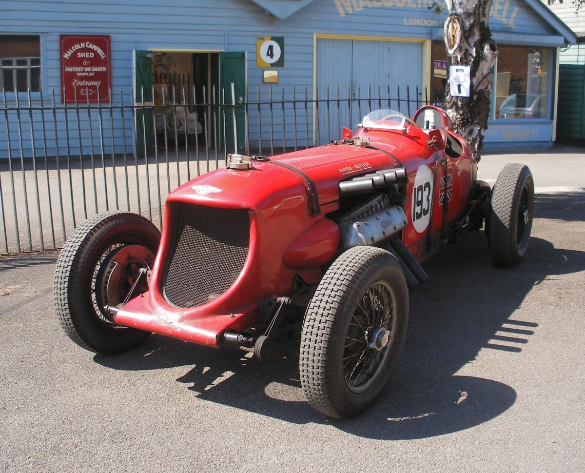 |
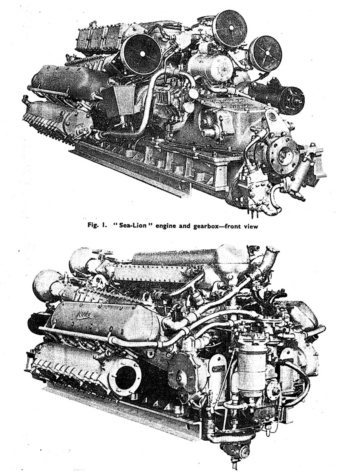
| Napier enjoyed great success with the Sea Lion version of its W-12, each of its inlet manifolds fed directly by a horizontal carburettor. The Sea Lion had originally been marinised by the British Power Boat Company. | As rebodied in 1980, the monoposto Napier-Bentley racer makes excellent use of a Napier Lion. It is a ‘modern’ version of the great cars that once amazed spectators with hair-raising speed on the Outer Circuit at Brooklands. |
Send mail to
![]() with questions or comments about this web site.
with questions or comments about this web site.
![]()