The Lycoming XR-7755
Working Topic 1948
by Kimble D. McCutcheon
29 Jan 1948. Blackwood's notebook contains a schedule for an unspecified test and hand-written test status notes.
| bhp | rpm | Time
(min) | Gear
Ratio | Cam, Spark
Setting |
|---|
| 1st Period – 15 hrs |
| 5,000 | 2,600 | 30 | 0.246 | Takeoff |
| 2,000 – 2,500 | Prop Load | 30 | 0.246 | Cruise |
| 2nd Period – 12.5 hrs |
| 5,000 | 2,600 | 5 | 0.246 | Takeoff |
| 3,000 | Prop Load
(2,200 ± 90) | 10 | 0.246 | Cruise |
| 3rd Period – 15 hrs |
| 3,000 | 2,200 | Steady | 0.246 | TO Cams, Cruise Spark |
| 4th Period |
| 2,000 | 1,600 | Steady | 0.3536 | Cruise |
| 5th Period |
| Shift Tests: 65 reduction gear shift cycles, where a cycle is defined as two separate shifts, either low-to-high-to-low or high-to-low-to-high. Stabilization runs between shifts were at the discression of Lycoming. |
| 6th Period |
| Overspeed Tests: 10 overspeed runs at 120% of 2,300 rpm (or 2,760 ± 2%) with 4.5 min at 60-80% of 2,300 rpm. This was to be done with the 0.246:1 reduction gear ratio, takeoff cams and spark advance. |
Blackwood's hand-written status notes, dated 29 Jan 1948, indicate an uncorrected power of 5,120 hp at 45.2 inHgA and 22°C (71.6°F) carburetor temperature. The corrected output was 4,950 hp. Brake specific fuel consumption was 0.60 lb/hp/hr. Runs at 1,000, 1,200, 1,300 and 1,600 to 2,600 had been completed. Blackwood notes that five or six hours had been accumulated without any cooling jacket cracks. [RG 342 RD2311. XR-7755, 503-602 Current]
17 Feb 1948. Lycoming's A.H. Coyne and R.B. Ingram produced a schedule for the third XR-7755-1 Engine No. 101 50-hr endurance test, Project T-245, Supplement Item No. 4.
- Object. This 50-hr endurance test was to be run in accordance with AAF Specification No. XR-28398-A dated 17 Jan 1944.
- Test Equipment.
- All testing was to be conducted on Test Stand #3.
- Power was to be absorbed by a 4-blade Curtiss Electric controllable-pitch steel propeller, Dwg. No. C7445, no 150411.
- Torsional vibration amplitude measuring equipment was to be operated only during run-in and for the first few periods in the 2,600 rpm takeoff operating condition. The torsional vibration measuring equipment was to then be removed for the remainder of the test.
- Fuel feed was to be via a Bendix Stromberg PR-100D1 pressure carburetor.
- Operating Conditions
- Conditions to be held constant during testing were:
- Fuel = AN-F-48a (Grade 115/145, superseding AN-F-33)
- Oil = AN-O-S Grade 1120 (Sinclair)
- Coolant = 70% AN-E-2a ethylene glycol + 30% water
- Coolant Tower Pressure = 15 psig
- Coolant Outlet Temperature = 185 ± 5°F for all speeds except 2,600 rpm; 203 ± 5°F for 2,600 rpm.
- Ignition Timing = 20° BTC through 2,200 rpm; 12° above 2,200 rpm
- Carburetor Inlet Air Temperature = 100°F, +10°F, -0°F
- Exhaust Pressure = Atmospheric
- Oil Scavenge Outlet Pressure = 40 ± 2 psi at 2,600 rpm; 30 ± 2 psi for all other speeds
- Valve Timing = Cruise setting through 2,200 rpm; takeoff setting above 2,200 rpm.
- Valve Tappet Clearance = 0.250" cold
- Run-In. The following 6-hr run-in schedule was to be followed for new replacement piston and cylinder barrel assemblies:
| rpm | Minutes | ADMP (inHgA) | bhp | Fuel Flow (lb/hr) |
|---|
| 1,200 | 20 | 14.0 | 492 | 260 |
| 1,300 | 20 | 15.0 | 614 | 300 |
| 1,400 | 20 | 16.0 | 750 | 380 |
| 1,500 | 30 | 17.0 | 960 | 460 |
| 1,600 | 40 | 18.0 | 1,170 | 530 |
| 1,700 | 40 | 19.6 | 1,400 | 620 |
| 1,800 | 40 | 22.0 | 1,670 | 740 |
| 1,900 | 40 | 24.5 | 1,960 | 860 |
| 2,000 | 40 | 27.3 | 2.280 | 1,020 |
| 2,100 | 30 | 30.0 | 2,650 | 1,200 |
| 2,200 | 10 | 33.0 | 3,030 | 1,420 |
| Shift to takeoff cam setting and 12° BTC spark timing |
| 2,300 | 10 | 36.0 | 3,470 | 1,800 |
| 2,400 | 10 | 39.2 | 3,930 | 2,100 |
| 2,500 | 10 | 42.5 | 4,450 | 2,500 |
- Endurance Test
- The first 15 hours was to consist of alternate periods of 30 min at 5,000 hp and 2,600 rpm, and 30 min at 40 – 50% takeoff power at a speed to be determined by the propeller load curve.
5,000 bhp Operating Conditions:
- Fuel Flow = Best power or richer if necessary to suppress detonation
- Engine Speed = 2,600 rpm ± 50 rpm
- Manifold Pressure = 46 –48 inHgA
- Camshaft Position = takeoff
- Ignition Timing = 12° BTC
- 40 – 50% Takeoff Rating, 2,000 – 2,500 bhp
- Fuel Flow = Best power or richer if necessary to suppress detonation
- Engine Speed = 2,600 ± 50 rpm
- Manifold Pressure = 46 – 48 inHgA
- Camshaft Position = Takeoff
- Ignition Timing = 12° BTC
40 – 50% Takeoff Rating, 2,000 – 2,500 bhp
- Fuel Flow = Best power or richer if necessary to suppress detonation
- Engine Speed = 1,950 to 2,050 rpm
- Manifold Pressure = 26 – 30 inHgA
- Camshaft Position = Cruise
- Ignition Timing = 20° BTC
- 12.5 hrs of alternate periods of 5 min at 5,000 hp operating conditions and 10 min maximum cruising conditions as follows:
5,000 bhp Operating Conditions, same as described in paragraph C 1.
Maximum Cruise Rating, 3,000 bhp
- Fuel Flow = Best economy or richer to suppress detonation
- Engine Speed = 2,200 ± 80 rpm
- Manifold Pressure = 33 – 34 inHgA
- Camshaft Position = Cruise
- Ignition Timing = 20° BTC
- The final 22.5 test hours were to consist of continuous operation at maximum cruising speed and power at 3,000 bhp, same as described in paragraph C 2.
- Upon completion of the 50 hrs continuous operation and without intervening disassembly, the engine was to be subjected to 10 overspeed tests of 30 ± 3 sec at 120% normal rated speed as follows:
- Engine Speed = 2,760 ± 50 rpm
- Fuel Flow= As required to obtain uniform engine acceleration
- Manifold Pressure = Lowest practicable for satisfactory engine firing
- Camshaft Position = Takeoff
- Ignition Timing = 12° BTC
- Stabilization Period = Each dive was to be alternated with stabilized runs of about 5 min at approximately 1,400 – 1,800 rpm. Acceleration and deceleration were to be accomplished in a period not exceeding 10 sec.
- General Notes
- Fuel flow at all times was to be rich enough to prevent detonation.
- Camshafts were not to be shifted at speeds above 1,600 rpm.
- Following each stop, the engine oil sump was to be drained before the next start and the engine pulled through by hand.
- The magnetic plug and scavenge pump inlet screen were to be inspected at run-in completion and a convenient periods thereafter. Elapsed operating time between these inspections was not to exceed 10 hrs.
- All fuel flow and counter rpm readings were to be for a period of not less than one minute except during dive tests.
- Cylinder barrel and spark plug gasket temperatures were to be taken at cylinders 7D and 8B exhausts.
- Endurance test time was not to be credited by increments shorter than 30 minutes, except hen shorter periods were a test requirement.
- Barometer and wet/dry air temperature readings were to be taken at intervals not exceeding three hours.
- Actual power output during the endurance test was to be computed on the basis of manifold pressure correction charts obtained from calibration running of XR-7755-102 on dynamometer stand No. 1. Torquemeter horsepower was to be computed at all engine settings to check on the power computed from manifold pressure correction charts.
- Data recorded during the subject test was to be include all that was listed in section F-4n(1), (2) and (3) of AAF Specification XR-26398A with the exception of exhaust pressure, which was not recorded due to the use of open exhaust stacks.
- Engine was to be weighed before installation on the test stand.
- Test instruments were to be calibrated before tests.
- A Sperry Knockmeter with pickups on eight cylinders was to be used throughout the test to detect detonation.
- Carburetor inlet air temperature was to be maintained at 100 +10 -0°F. If for some reason this temperature could not be maintained a decision was to be made at the time.
- In addition to accessories already on the engine , it was tentatively expected that tow generators and one hydraulic pump were to be furnished by the Army. Details on these accessories, their loading methods and equipment necessary to test them was to be furnished as soon as practicable.
- A Pesco fuel pump furnished by Lycoming was to be connected in series with the control room fuel pump. The Pesco Pump inlet pressure was to be held as low as practical (1 to 5 psia) and the outlet pressure between 16 – 18 psi.
[J.G. Blackwood Notes. RG 342 RD2311 XR-7755, 1943-1948: 503-602 Engineering Data.]
24 Mar 1948. Blackwood assembled an accounting of Lycoming utilities sources and consumption.
Lycoming Utility Consumption
| Utility | Supplier | Consumption |
|---|
| Electricity, 440V 3Φ 60Hz | Pennsylvania Power & Light Co. | ~760,000 kwh/mo (Exp Lab =~72,000 kwh/mo) |
| Water | Williamsport Water Co | ~7 million gal/mo |
| Gas | Pennsylvania Power &Light Co. | ~175,000 ft³/mo |
Transformers: Total = 10,707kva; largest transformer = 12kv – 1,500kva; smallest = 4kv, – 125 kva
Big dynamometer motoring capacity = 600 hp
High-speed supercharger dynamometer air capacity = 20,000 lb/hr
[Penciled notes by J.G.Blackwood. RG 342 RD2311 XR-7755, 1943-1948: 503-602 Conf and Tel Notes.]
13 Apr 1948. Pinto telephoned Blackwood to discuss the status of an unspecified XR-7755. Apparently, a generator had failed and the AMC wanted more details. The tachometer sender housing cover had cracked and been replaced. A distributor oil seal had leaked; the other distributor had a cracked mounting flange. There were minor oil leaks. The magnetic plug showed no signs of metal. The engine would be ready to resume testing on 15 April. There had been propeller trouble the day before due to faulty clutch springs. [Penciled notes by J.G. Blackwood. RG 342 RD2311 XR-7755, 1943-1948: 503-602 Conf and Tel Notes.]
 |
 |
 |
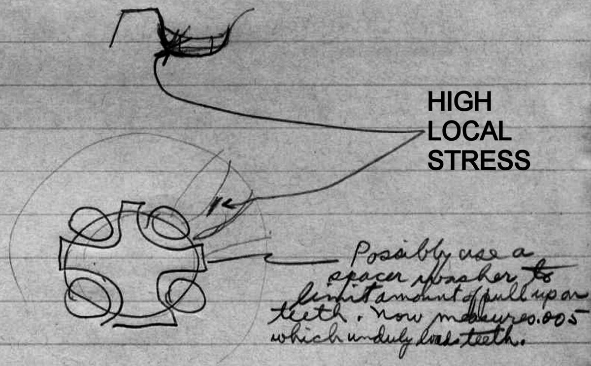
| Blackwood's sketch of the Lycoming crankpin joint depicts its troubles. The P&WA joint (center) and its fastener (right), which carried almost as much power, used a single large fastener instead of Lycoming's four. The single fastener was not prone to the uneven loading peculiar to the four-bolt joint. |
25 May 1948. Ryder, who was visiting Wright Field, reported that the 3-cylinder engine with a floating master rod bearing would run that week or next. The XR-7755 reduction gear had been tested through 2,600 rpm without load; the design was being improved. The second reduction gear unit was ready for assembly. Next step was to run the two reduction gears nose-to-nose. Scintilla was cooperating on the ignition system and would provide new distributors, new harness but keep the same magnetos. Blackwood instructed Ryder to check whether the oil sump needed to be enlarged before being acceptable for testing.
Crankshaft stresscoat testing had revealed high local stress in the roots of crankpin face splines adjacent to the fasteners. The engineers were considering using a spacer inside the ring of teeth to limit the fasteners' clamping force. [Penciled notes by J.G.Blackwood. RG 342 RD2311 XR-7755, 1943-1948: 503-602 Conf and Tel Notes.]
19, 20 Apr 1948. Blackwood notes that he was on hand for the tear-down inspection after the first XR-7755-1 50-hr test at 5,000 hp was completed
- The coolant manifolds featured a band around the standard gusseted cylinder assembly; the cylinders were satisfactory with no tube breakage.
- Some coolant seepage was evident at the coolant manifold gaskets after shutdown. Was an AN gasket material intended for high temperature use? The other gaskets had fared better.
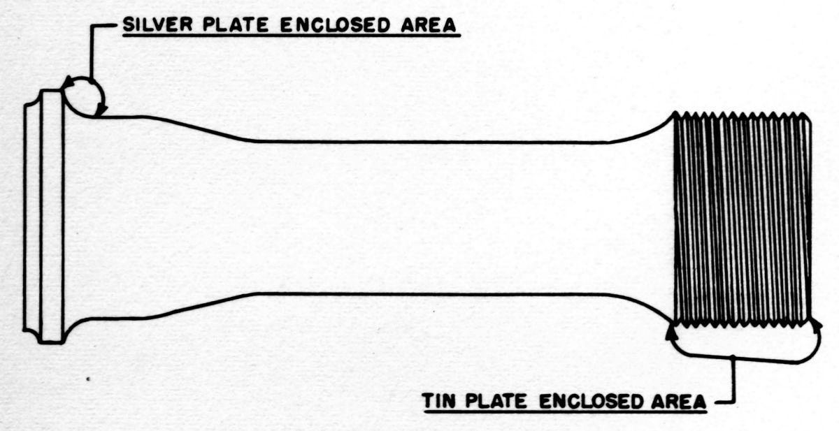
- The knuckle pins looked very good except for the #3B, which had a 0.5" x 0.125" spot near an end that was missing its silver plate. Was this due to a poor bond?
- There was copper in the bearing back bore, perhaps from a shim against the outer race to clamp and retain the bearing. None of the associated parts were in poor condition.
- There was blowby between the 2nd and 3rd rings of one piston. The top rings were slightly pitted and streaked but had apparently been working well. The pistons exhibited medium-hard carbon deposits. Several piston pin retainers had gouged the piston. A few pistons were slightly scratched but most were in very good condition.
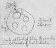 |
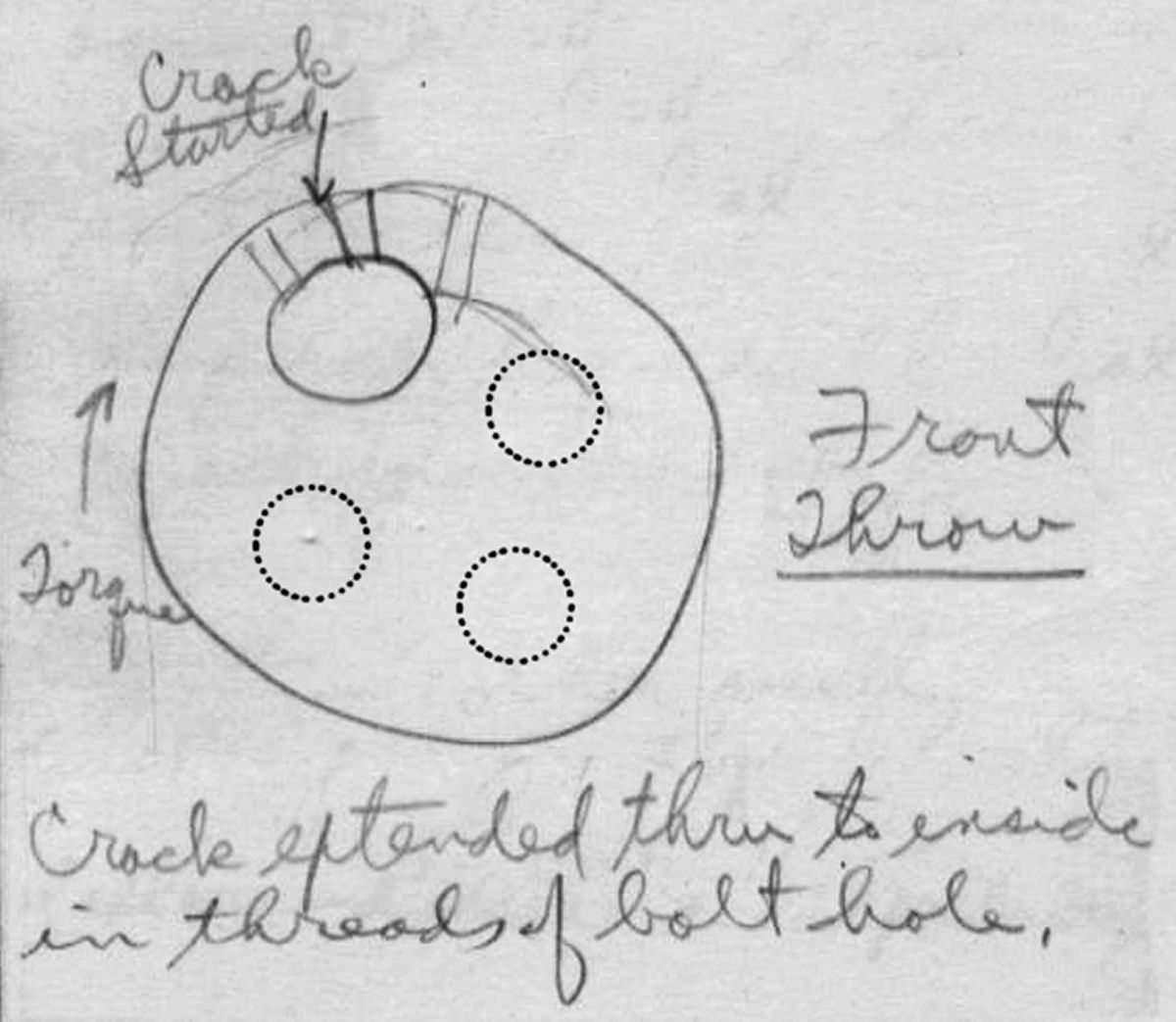
Blackwood's
Crankpin Crack
Sketch |
- A crack was found in the front crank pin, starting at a face spline tooth root and extending to the bolt hole threads. Clearly further crankpin joint study was required. Torsional studies were planned with the crankshaft driven directly; in previous studies it had been driven through several shafts and gears. Increasing the face spline root radius from 0.040" to 0.090" was being considered. During the additional testing Lycoming planned to compare changed sections with sections already tested, as well as comparative stress checks on old and modified parts.
- The B- and D-row master rod bearing shells had cracked at the serrations used to prevent rotation. The D-row shell retainer had cracked straight outward at one serration. The B- and D-row bearing shells showed "cavitational fatigue" on the lead-indium plating and light scratching; the journals were also lightly scratched. The master rod end seals were worn from contact with the knuckle pin ends. These seals were soft (Rockwell C hardness of just 32); Lycoming planned to make the seals harder.
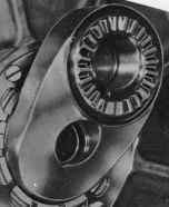
- The supercharger shaft oil seal consisted of tandem bronze rings running inside steel shells. The aft bronze ring had gouged its shell, allowing oil into at least four of the induction manifolds. The supercharger housing was in good condition. The supercharger damper springs had caused slight wear on the damper gear hub. The supercharger thrust bearing had pickup up some of the bronze thrust washer. Lycoming planned to try another material in one of its R-680 engines.
- The 1C and 4D exhaust valves were lightly guttered in one spot. The 6D exhaust valve was ring all around, as was its seat – probably caused by dirt under the valve seat.
- The cylinder heads and valve seats were in good condition. There was some carbon accumulation, but no evidence of seat guttering. A narrow seat remained in all cases.
- The Nos. 1 and 8 manifolds were missing backfire screen sections; the pieces had gone through the engine.
- One ignition wire had failed inside the stainless steel harness tube. Clips on the harness tube had failed, as had the main harness ring. One distributor flange had failed, which led to an oil leak that damaged it internally and requiring replacement. The distributor flange had broken because of casting porosity. One distributor cap contactor spring had failed and been replaced. The Bendix-Scintilla magneto drawing number was 10-27600-4 and the distributor drawing number was 10-29991-1.
- The tachometer drive housing plate had cracked from the electric tachometer being overhung; Lycoming planned to add ribs to stiffen the plate.
- Blackwood penciled a reminder to check with Allison and Rolls-Royce to see what kind of hose and hose clamps they were using. During the Lycoming 50-hr test it had sometimes been necessary to tighten clamps to stop coolant seepage.
- Blackwood observed that the 100°F carburetor air temperature in conjunction with reduced spark advance was giving better sfc because the combination was not detonation-limited as soon. This was counterintuitive since a greater spark advance would normally be better. The carburetor's charge cooling effect was largely dissipated before reaching the cylinder. He opined that fuel injection would permit greater spark advance and better sfc.
- The crankshaft rear dynamic vibration absorber pins were pitted and metal had been picked from them. The crankshaft pin holes did not exhibit similar pitting but were slightly worn over a small outboard sector.
- Gear teeth on the front transfer coupling showed flight nitride layer flaking at the tips. This would be acceptable when they were lightly ground.
- The camshaft cams looked good, but two or three cam rollers showed slight gouging on the roller radii.
- The scavenge pump housing showed signs of rubbing. The aluminum gears, which ran against steel gears, were slightly scratched. The oil pressure pump relief valve was slightly scratched and showed a slight tendency to bind.
[Penciled notes by J.G. Blackwood. RG 342 RD2311 XR-7755, 1943-1948: 503-602 1st 50-hour Test at 5,000 hp.]
8 Jul 1948. Lycoming's Clarence Wiegman visited Wright Field and briefed Blackwood on crankshaft crankpin joint studies. A spacer under the crankpin joint bolts reduced face spline tooth root stress by 50%. A larger root radius did not help. Specimens were under test on the endurance tester to check if other problems, such as tooth fretting, may have been introduced. When engine #102 was rebuilt, this new crankshaft design would be used.
The ignition harness was progressing.
The floating master rod bearing had not done well when tested on the 3-cylinder engine. Lycoming was going to install the master rod bearing with an interference fit and try again.
Some lightly-loaded bearings in the dual-rotation gearbox had given trouble; this was traced to preserved bearings having pitted. Test cell sound proofing was promised by 1 Sep 1948. [Penciled notes by J.G. Blackwood. RG 342 RD2311XR-7755, 1943-1948: 503-602 Conf and Tel Notes.]
19 Aug 1948. Ryder reported that engine #101 subassemblies were built and that the crankshaft was supposed to be complete by 1 Sep 1948. It would be assembled with the 0.56 reduction gear.Lycoming planned to check out engine #102 on the dynamometer before #101 started its second 50-hr test. The reduction gear test was scheduled to complete on 25 Sep 1946. The 3-cylinder engine with a pinned master rod bearing was working out well. [Penciled notes by J.G. Blackwood. RG 342 RD2311 XR-7755, 1943-1948:503-602 Conf and Tel Notes.]
30 Sep 1948. Pinto called Blackwood with news that engine #101 was scheduled to run on 11 Oct 1948; it was now ready to be mounted on the test stand. Test cell sound proofing was complete. Engine #102 was awaiting crankshaft parts; it was to undergo performance testing on the dynamometer. The nose-to-nose reduction gear test ran for 35 hrs at cruise and 10 hrs at takeoff power before encountering pinion bearing trouble on one unit, probably due to a lubrication fault; the second unit appeared healthy. [Penciled notes by J.G. Blackwood. RG 342 RD2311XR-7755, 1943-1948: 503-602 Conf and Tel Notes.]
18 Nov 1948. On this date using a Memo Routing Slip Blackwood provides the following status information:
9 Nov 1948. Drive Unit #1 of the reduction gear nose-to-nose test failed after 7 hrs retesting. The failure resembled a previous failure in that four pinions of the fixed reversing carrier seized and rotated in spite of having been staked. This latest failure indicates that the new design in which the pinion bushings were staked and thrust face oil pockets were provided was unsatisfactory. The #101 nose section with the same design failed first; now that a second failure had occurred and proven the design unsound, the #101 nose section had been removed and the pinion bushings were being replaced with ones similar to those that had successfully completed the original 50-hr test. Engine #101 was expected to be ready for test around 15 November.
16 Nov 1948. Engine #101, which was undergoing a Preliminary Flight Rating Test, stopped after one hour due to an oil leak at the rear accessory plate. A loose pipe plug was replaced and staked in place to prevent further leakage.
17 Nov 1948. Engine #101 was shut down after four hours endurance running due to oil leaks at the front adapter plates parting surface and at valve cover to cylinder head parting surfaces on several banks. The No. 4 bank leak was due to a sand hole in the valve cover, which necessitated replacing the cover. The oil sump magnetic plug exhibited several bits of cotter pin and a tab washer locking tab. The nose section was being removed for inspection of all cotter pins and tab washers. Testing was expected to resume around 22 Nov 1948. [RG 342 RD2311. XR-7755, 503-602 Current]