The Lycoming XR-7755
Working Topic 1946
by Kimble D. McCutcheon
Early 1946. Blackwood compiled a Lycoming XR-7755-1, -3, -5, -7 Contractual Data summary:
Contract No. W33-038 ac-564 (1943) – $1,571,575.00 – Partially finished parts for three engines; three rough forging sets, castings and bearings; single- and three-cylinder engine testing; component testing.
Contract No. W33-038 ac-564 (1944) – $2,080,000.00 – In addition to 1943 amount: Complete two engines and one spare set; provide additional single- and three-cylinder testing as well as XR-7755 testing; parts for two-speed dual-rotation reduction gearing.
Supplement No. 7 (1946) – $893,931.00 – Additional single-, three-cylinder and XR-7755 engine testing; reduction gear assembly and test.
Initiated Contract Change – (no price change) – Development and testing curtailment except as required to complete 50-hr Flight Approval Test (AAF Spec XR0-28398A) on an XR-7755-1 or XR-7755-3.
| Performance | shp | sfc | Physical Characteristics |
|---|---|---|---|
| Takeoff | 5,000 | 0.70 | Length = 121.35" |
| Military at 35,000 ft | 5,000 | 0.70 | Width = 60.50" |
| Maximum Continuous at 35,000 ft | 4,000 | 0.42 | Depth = 60.50" |
| Shaft Horsepower at Minimum sfc | 2,000 | 0.37 | Height = 66.50" |
| Dry Weight = 6,050 lb | |||
| Fuel Grade = 115/145 |
Design Features: The XR-7755-3 and -7 engines are flight engines are designed to have two-speed dual-rotation gearing. Reduction ratios are 2.83:1 and 4.06:1. This is a 36-cylinder liquid-cooled radial composed of four rows of nine cylinders each. The XR-7755-3 had a pressure carburetor while the XR-7755-7 had fuel injection. Cylinders were 6.375" bore x 6.750" stroke; compression ratio was 8.5:1.
Objectives and Applications: An engine of low specific fuel consumption and adequate power for long-range aircraft. No specific airplane application.
Status: The engine was in development. Two experimental engines and spare parts had been built. A 50-hr development test at 4,000 bhp had been accomplished.
In Report No. 962, detonation limited imep is 260 at 2,800 rpm and 271 at 2,600 rpm.
The PPL advocated development of a float-operated device to prevent engine lubricating oil aeration. [RG342 RD2311. XR-7755.]
15, 16 Jan 1946. Blackwood's hand-written pencil notes give an account of his visit to Lycoming. A Lycoming labor strike had suspended all XR-7755 part machining and assembly work. Work proceeded on the new building and XR-7755 testing. The 1-cylinder head was being set up for valve gear tests that would examine fatigue. In addition, a smaller supercharger impeller was being tested. The reduction gear setup was also being tested, along with the engine mounts.
14, 15 Jan 1946. Blackwood's subsequent memorandum report on the trip repeats some of the information in his notes but also adds more information. The labor strike that had started around 15 January had completely suspended all parts machining, parts testing, and assembling the first XR-7755. The Engineering group was still in operation as was construction on the new facility. Hence, work completion estimates were from the time the strike ended.
The first XR-7755 crankcase, crankshaft, connecting rods and two cylinder blocks had been assembled. All but two remaining blocks were expected to be available by the time the others were installed. The accessory case and supercharger section were completely assembled and to be mounted on the supercharger test rig for running prior to assembly on the engine. The setup for running-in the accessory section was expected to require about 1.5 days. The nose section had not been assembled, but all parts except two were ready for assembly and the two parts would require less than a week to assemble. No major assembly difficulties had been encountered and Lycoming projected completion in about two to three weeks. The first engine would have a direct propeller drive and would be run on the propeller test stand with a cut down propeller club.
In view of this parts status, Lycoming expected second engine buildup to begin in about four weeks. It would use the 1:1 reduction gear. The 0.56 reduction gear parts were the same as some used in the final dual-rotation reduction gear. All of these were scheduled to be through the machine shop in approximately five months. Therefore, the first engine suitable for dynamometer running with the 0.56 reduction gear, would not be available for five months. At about that time parts to start the dual-rotation nose-to-nose endurance test would be available.
After the post-V-J-Day work stoppage, construction on the new facility had resumed during the first week January. Some interior installation work had been ongoing for a longer period. Practically all equipment was available for building completion. The dynamometers were being cribbed up in preparation for sliding them onto the test beds. The large dynamometer equipment and piping installation remained to be finished. Lycoming personnel estimated completion in May 1946. Most small single-cylinder dynamometers were in place.
The drafting room was at work detailing the two-speed reduction gear shift control, which was intended to make automatic and fool-proof the steps involved in ratio shifts so that once a decision to shift was made all that was required was reducing the throttle. The drafting room was also revising various parts to make them lighter and more refined.
Blackwood requested that Lycoming cost reports be submitted to the ATSC on a more current basis. [24 Jan 1946 Memorandum Report TSEPP-5-504-3252. Contract W-33-038 ac-564 on Development of the XR-7755 Engine, P350314.]
18 Mar 1946. Blackwood noted that the Lycoming workers' contract was pretty well settled, but wage rate was NOT settled. [Penciled notes by J.G. Blackwood. RG 342 RD2311 XR-7755, 1943-1948: 503-602 Conf and Tel Notes.]
20 Apr 1946. Posthauer at Wright Field reported that wage disagreement resulted in failure of Lycoming workers to sign the latest contract proposal; next discussions were scheduled for 25 and 26 Apr 1946. [Penciled notes by J.G. Blackwood. RG 342 RD2311 XR-7755, 1943-1948: 503-602 Conf and Tel Notes.]
| Supercharger Inlet Pressure | 27.6 inHgA |
| Air Flow | 39,400 lb/hr |
| Supercharger Outlet Pressure | 45.5 inHgA |
| Air Inlet Temperature | 72°F |
15 Apr 1946. Stanley Lynn, a Consulting Engineer for Douglas Aircraft Co. in El Segundo, California, informed the PPL about a novel gas turbine and gear arrangement for a Douglas airplane. Lynn wanted a 6:1 reduction gear capable of transmitting about 5,500 hp. He opined that the XR-7755 reduction gear most closely approached their requirements and had already been developed. [RG 342 RD 3755. XR-7755 Verification Test – Lycoming, Cross Reference and Suspense Record.]
25, 26 April 1946. Blackwood visited Lycoming and reported that the labor strike, which started on 15 Jan 1946, ended on 9 Apr 1946, and that appreciable progress was again being made on the project. The first 36-cylinder engine was being fitted with camshaft shift indicators, and the only remaining work prior to assembly on the test stand was to install the accessory case and nose assemblies. The accessory case was being run-in separately and one part for the nose was to being completed on 26 April. The accessory case was mounted on the supercharger test rig and was on test. A five-hour run-in and eight hours of endurance testing at takeoff conditions had been accomplished:
Since then, a total of 15 hours endurance running had been accomplished. The only unsatisfactory conditions were a light scoring of the supercharger thrust washer and a leaky power takeoff drive seal.
Buildup of the second 36-cylinder engine was estimated to be about four months away. The parts status for it was as follows: crankcase = 90%; cylinder heads = 50%; accessory section = 90%. Machining for this engine's 0.56 reduction gear had been subcontracted and was promised in six weeks. The crankcase and crankshaft for this engine were to be used for spin tests prior to engine assembly. Major third-engine parts were progressing well also. Engine installation on the propeller test stand was to begin on 8 May 1946, and testing was to start on 23 May, with a six-hour run-in schedule up to 4,000 hp.
The two-speed dual-rotation reduction gear units had been subcontracted to improve delivery and relieve some of the Lycoming machine shop load. It was estimated that six months would be required to complete two units and four additional months would be required for the nose-to-nose endurance testing. When this testing ended, the first two-speed dual-rotation unit could be assembled on a 36-cylinder engine; this was the same version that was to be used for flight engines. The two-speed shifting parts had undergone 500 endurance cycles mostly at a rate-of-speed-change of 400 to 500 rpm/second. This was representative of similar studies done on the Lycoming XH-2470. However, in an attempt to aggravate the shifting problem, 10 shifts were made at 1,100 rpm/sec from low to high propeller and at 1,900 rpm/sec from high to low. Also, 85 normal shifts were made in a 25 minute period. No shifts were missed in any of this testing and the parts were in good condition. The only additional anticipated modifications was a slight chamfer on the low and high speed engagement gears to eliminate the very slight wear at that point.
One single-cylinder test engine was engaged in performance running and another on endurance. The latter was running tests on the latest cylinder design, but the most important thing on test were the McQuay-Norris piston rings. Lycoming's first choice had been Wilkening piston rings, which had the most test time. However, Wilkening had been uninterested in supplying larger quantities, which necessitated the crash program to qualify a second source. Lycoming was trying to bring other piston ring vendors into the program. A 150-hr endurance test pattered after the qualification test schedule of Specification AN9502b was to be started on a single-cylinder test engine in two to three weeks as soon as the 36-cylinder shiftable camshaft was available.
Blackwood pointed out to Lycoming, and Lycoming agreed, that fuel injection was almost a necessity for this engine. Single-cylinder tests had exhibited the knock limit and fuel economy superiority of fuel injection over carburetion; this would be even more pronounced in the 36-cylinder engine. The Bosch injectors had performed intermittently, failing to produce repeatable spray patterns, and the experimental equipment had not been of aircraft quality. Six Ex-Cell-O injectors were on order, promised in two to four weeks, and would be tested when they arrived. A new 36-cylinder intake manifold layout eliminated backfire screens and provided for port injection.
Design studies of the oil pressure pump inlet, outlet and housing. A larger, straighter inlet passage, more accessible inlet location and cleaner design had resulted from review of the original design. A one-piece crankcase with bolted-in diaphragms was also being studied.
Blackwood, in an undated hand-written note had projected remotely controllable test propellers by 1 Sep 1945 and remotely-controlled dual-rotation props by June 1946. At that time, Vonderkeit was checking on a remotely-controlled No. 70 test club from Curtiss, but was dubious over an August 1945 delivery date. Vonderheit had a No. 60-80 club, the aft propeller was adjustable, the fore prop was remotely controllable. Shaw, from McGee's office related that a No. 60-80 flight propeller was under development, but not high priority; delivery was promised for February 1947. [Penciled notes by J.G. Blackwood. RG 342 RD2311 XR-7755, 1943-1948: 503-602 Conf and Tel Notes.]The ATSC was looking into the test propeller disconnect.
The older building in which test fixtures, tear-down and build-up rooms, and offices were located was being reworked to accommodate office space. At the same time, single-cylinder testing was ongoing, making the transition period difficult.</ol> [24 May 1946 Memorandum Report TSEPP-503-3269. Contract W-33-038 ac-564 on Development of the XR-7755 Engine, P350441.]
(Note: the following disorganized stream-of-consciousness collection of conference talking points and notes covering eight years will hopefully gain organization as additional information is uncovered by this writing process.)
9 May 1946. Telephone conversation with Lycoming's Carpenter. The 36-cylinder engine was put on the stand on 8 May 1946 and setup was ongoing. Lycoming estimated it would be ready to fire in 7 to 10 days. Crankshaft test pieces had been at 2,000,000 cycles and a crack had appeared at the root of a short spline tooth. The test was being run at takeoff equivalent conditions. Another identical piece was immediately run to determine the safe power limit; takeoff power may be temporarily limited to 4,000 hp. Lycoming was considering several alternative joint configurations, including four smaller bolts, one large bolt, and modified teeth.
In the preparation for an undated Routing and Record sheet to the Propeller Laboratory. Blackwood referenced Lycoming Technical Report No. 1002 (title not stated) and asked that the Propeller Laboratory study the report and provide comments on the procedure and feasibility of the proposed two-speed propeller drive shifting mechanism. Lycoming was proceeding with this propeller drive scheme, which was planned for the first test two-speed stand engine, a dual-rotation drive with a test club; this was 10 months away. MatCmd had determined that the Lycoming shift scheme was adequate for the task at hand. A 26 Jul 1946 letter to Lycoming stated t hat a dual-rotation propeller with rear propeller adjustment and front propeller remote control was available. In a 28 Feb 1946 letter, MatCmd stated that the injection program was a necessity. Lycoming was contracting parts to available vendors in order to assure quicker delivery. In Report No. 961, Lycoming proposed the use of a low-tension ignition system, a substitution to which Lycoming agreed. Lycoming report Nos. 237, 259 and 961 concerned failed camshaft bearing caps. Stress coat investigation was to proceed. Lycoming was working up rolled-thread strength tests, presumably for the crankshaft bolts, and also researching graphite coated pistons from J.J. Wills, ALCOA and Cleveland.
Some potential future programs were discussed, including water and dimethylamine injection to boost takeoff rating and for better cruise economy; apparently the theory was that the combination would allow more spark advance and higher cruise power.
Lycoming Report No. 962 explored the use of higher bmep, potentially 260 psi at 2,800 rpm and 271 psi at 2,600 rpm. The accessory case had been run in for 5 hrs at full speed; there was apparently minor trouble with thrust bearings and seals. Bosch was to have a speed-density control available soon. The XR-7755 was to be on the test stand by 9 May 1946 and on test by 23 May. After about 6 hrs running, it was to be removed from the stand and torn down for inspection.
Lycoming estimated the two-speed gearbox would be ready in 6 months, with 4 more required for tests to complete the item. Spin tests were to be run on second crankcase and crankshaft prior to use on the second engine, which was expected in 8 months instead of 3. There was a choice of using parts for a second 4-cylinder engine but more probably on the second 36-cylinder engine.
The ongoing two-speed shift tests of over 600 hrs had been severe, with part of the testing done at accelerations three times greater than normal, all in an attempt to miss a shift and expose parts to enhanced endurance testing. The mechanism had survived well, with only a bit of chamfering on the balk ring and driving gears.
17 May 1946. The XR-7755 was first started after initially experiencing carburetor and ignition trouble. Ran for 1 hr up to 1,200 rpm. [Penciled notes by J.G. Blackwood. RG 342 RD2311 XR-7755, 1943-1948: 503-602 Conf and Tel Notes.]
6 Jun 1946. Blackwood visited Lycoming and observed the first XR-7755 operating on the propeller test stand. The engine had accumulated about 4.5 hrs running at up to 1,300 rpm with a wooden test club. An undrilled camshaft bearing oil passage had caused its failure with no other damage. Minor ignition and carburetor difficulties had been encountered and remedied. Blackwood observed for 35 minutes and declared the run quite satisfactory. The open exhaust stacks showed fairly even flames and distribution at 1,300 rpm, but excessive idle richness was observed, but largely corrected by an idle adjustment. The engine produced approximately 1,500 hp at 1,300 rpm and 26 inHgA manifold pressure. The engine was scheduled to continue a run-in schedule through 2,200 rpm and 4,000 hp, but this would be delayed until another propeller was received. The one in use was cracked, which resulted in the 1,300 rpm limit. A propeller shipped from Wright Field on 22 May 1946 was delayed by a rail strike and had not been located despite efforts by both Lycoming and Wright Field.
At some point after the first XR-7755 ran and during the building of the second XR-7755, Lycoming simplified the nomenclature; the "first XR-7755" became "#101" and the "second XR-7755" became "#102". From this point forward, the revised nomenclature that will be used.
One single-cylinder engine was in operation after having recently accomplished a 100-hr endurance test using a maximum equivalent rating of 5,000 hp and two 100-hr tests using a maximum equivalent ration of 6,000 hp. These tests were run on the same set of McQuay-Norris piston rings, which were in satisfactory condition after these tests. This was gratifying since Lycoming had been forced to install McQuay-Norris rings on the 36-cylinder engine with very limited test background after Wilkening, the original ring vendor, failed to supply rings. A spark plug test program was planned in an effort to choose better plugs than the Champion CR-341 plugs that have tended to foul in the 36-cylinder at the rich, low speed running that been accomplished.
Lycoming had presented a proposal for a compounded XR-7755 to the ATSC on 6 Jun 1944.
The new building was still progressing. The first single-cylinder engine test setup was expected to be completed in a week. The other three were to be completed within a month. Multi-cylinder dynamometer instrumentation had been completed and its stand was to be complete by the end of July. The coolant pump test setup was in operation. The connecting rod test fixture had been operated and inspected; it was to be built up using new parts to increase the rod loads to rated values. A multi-cylinder head had been set up and was to be endurance tested and studied in operation. The crankshaft test fixture was not in operation but had recently tested a single-throw piece with four clamp bolts smaller than had been used before to increase the face spline area (since ample bolt load was available.) This piece passed a 10-million cycle test at 90,000 lb/in bending torque, 120,000 lb/in static torque and 40,000 lb/in vibratory torque. It then developed a crack at 2-million cycles and 50,000 lb/in vibratory torque. This is an improvement over the former standard test piece. Another test piece incorporating a single large bolt is ready except for special wrenches required to tighten that bolt to the required elongation.
Blackwood opined that "Lycoming should be complimented for the thoroughness and planning which have gone into this development to permit initial XR-7755 engine assembly and initial running with such an unusually small amount of difficulty. It is felt that this in itself is quite an accomplishment regardless of development problems which may be expected to arise as the engine accumulates test time." [11 Jun 1946 Memorandum Report TSEPP-503-3270. Contract W-33-038-AC-564 On Development of the XR-7755 Engine, P350446.]
25 Jun 1946. Jack Carpenter of Lycoming telephoned Blackwood to notify him that #101 had been running at 2,100 rpm, the equivalent of 3,100 hp, for about 1 hr. The test team next planned to run it at 2,200 rpm, the equivalent of 3,500 hp. Total time running was then between 8 and 10 hrs. General Electric was cooperating on a compounding study.
1 Jul 1946. Fred Jones of Lycoming telephoned Blackwood to inform him that the two-speed control tests were complete and the unit was being torn down. [Penciled notes by J.G. Blackwood. RG 342 RD2311 XR-7755, 1943-1948: 503-602 Conf and Tel Notes.]
| Rating | imep (psi) | isfc (lb/hp/hr) | rpm | Estimated Equivalent, 36-Cylinder bhp | bsfc |
|---|---|---|---|---|---|
| Takeoff and Military | 264 | 0.58 | 2,800 | 6,000 | 0.70 |
| Normal | 251 | 0.52 | 2,400 | 5,000 | 0.61 |
| High Cruise | 155 | 0.35 | 2,200 | 3,000 | 0.39 |
| Medium Cruise | 143 | 0.333 | 1,600 | 2,000 | 0.37 |
| Low Cruise | 90 | 0.34 | 1,300 | 1,000 | 0.39 |
[16 Aug 1946 Memorandum Report TSEPP-503-3280. Contract No. W-33-038 ac-564 on Development of the XR-7755 Engine, P350500.]
7 Aug 1946. The knuckle pin grooves and flats had been altered to make them more durable, and the new version was testing well. A new engine build was scheduled in about a week, as soon as a full set of the new knuckle pins could be built. Apparently someone wanted an engine demonstration; Lycoming thought that could be accomplished during the first week of October 1946.
Consolidated had analyzed its needs for heavy bomber Curtiss propellers: the 6-blade version would need to be 20 feet in diameter, the 8-blade version 18 feet in diameter.
The Lycoming BX had been mounted in a test stand on 1 October; Lycoming had requested 500 gallons of ethylene glycol.
[Penciled notes by J.G. Blackwood. RG 342 RD2311 XR-7755, 1943-1948: 503-602 Conf and Tel Notes.]
20 Aug 1946. Blackwood/Lycoming telcon.
John Carpenter reported that the new pins had been delayed 10 days because the silver plating failed the black light inspection at Mallory. The new pins passed the ALCOA fatigue test. Bendix had visited to propose a new single 36-cylinder injector. Bosch was expected to supply nozzles that week. Hamilton Standard advised that a propeller for the two-sped dual-rotation test was available, but final ordering was delayed until after a Hamilton Standard/Propeller Laboratory conference that was to occur 20-21 Aug 1946. There had been no requirements change on propeller speeds, gear ratios and usage methods. Subassembly buildup for the 2nd engine had begun.
Posthauer asked about the compound proposal status and was told MatCmd expected its release in September 1946. Posthauer was advised to envision an modified compound program through first phases as well as a normal continuation; also advised to reexamine quotes since the ones submitted were higher than previous 1-cylinder running.
Earle Ryder inquired about ethylene glycol and was advised that Middletown Depot had been advised to ship same. Requested changes to the proposed change order revising Item 12-5 test conditions; he was rewriting it to include 12° instead of 15° spark advance; 264 imep instead of 258; Normal rpm = 2,500; "tests run hereafter" can cover at time of test on those not already covered; limit the testing to 1-cylinder engine since 3- and 4-cylinder engines would not be concerned with maximum output. [Penciled notes by J.G. Blackwood. RG 342 RD2311 XR-7755, 1943-1948: 503-602 Conf and Tel Notes.]
|
|
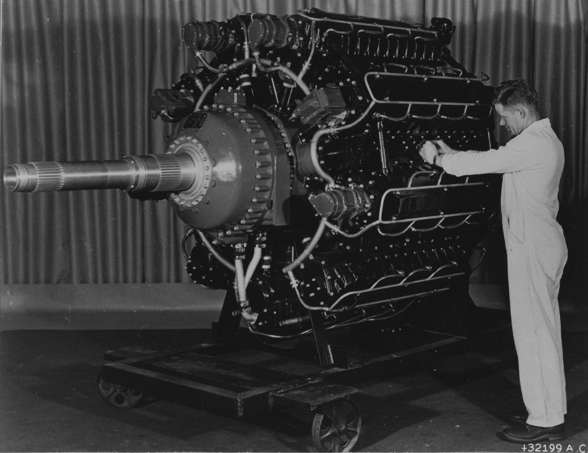
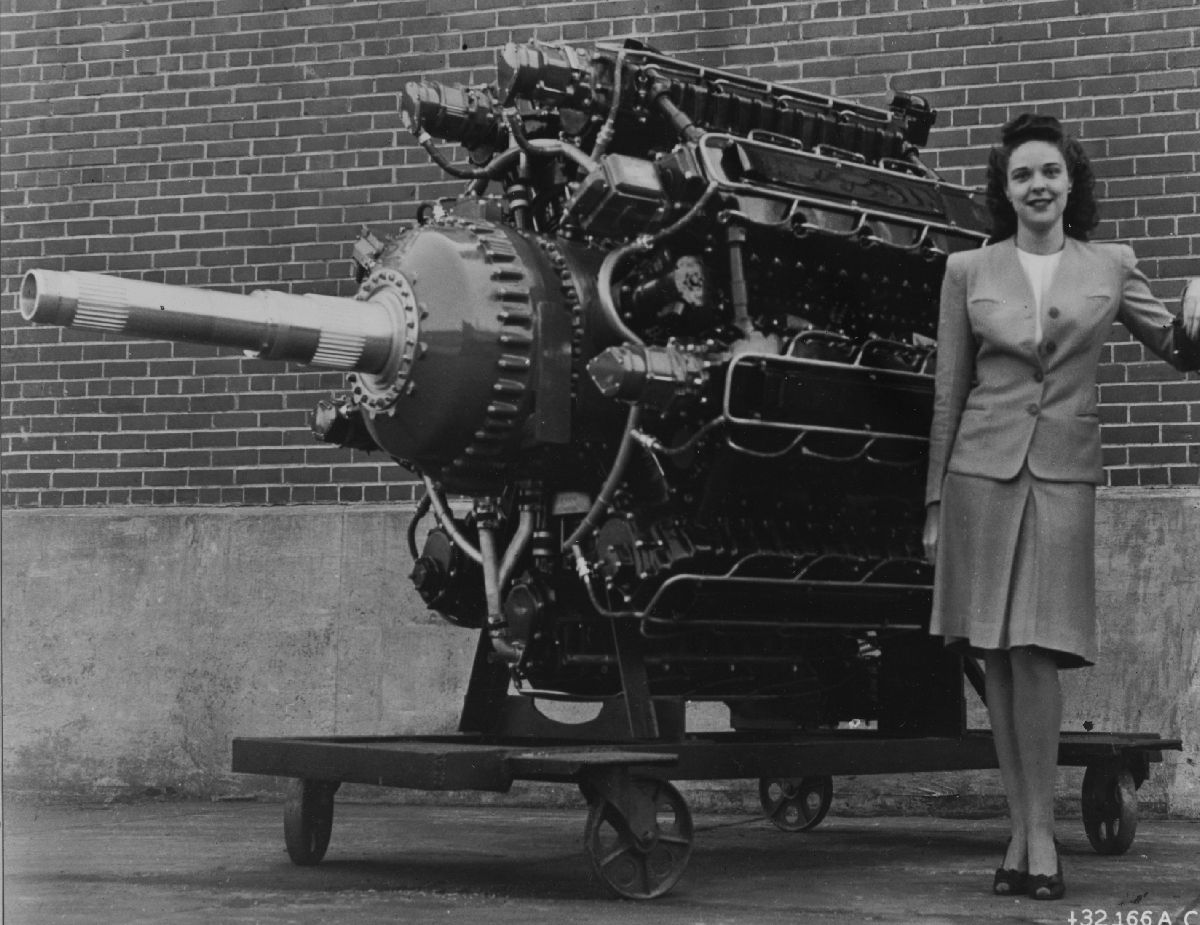
| "AAF UNVEILS NEW ENGINE – This is the world's most powerful reciprocating aircraft engine, the XR-7755-3, which will be unveiled by the Army Air Forces, Thursday, October 31, 1946 at the Lycoming Division of the Aviation Corporation in Williamsport, Pennsylvania. The engine develops 5,000 horsepower at takeof—equivalent to the power produced by a modern railway locomotive. Lycoming employees stand beside the new engine to give an idea of its size." | |
10 Sep 1946. Posthauer and Carpenter of Lycoming, and Col R.J. Minty, Col R.L. Wassel, Col R.J. O'Keefe, A.L. Berger and J.G. Blackwood of the Air Materiel Command (AMC) met to discuss future XR-7755 developments. Posthauer announced that if there were no objections by the AMC Lycoming was planning a general gathering in Williamsport of Army, military aircraft contractors and airlines in 31 Oct 1946. The XR-7755 was to be exhibited, probably running on the test stand, and the new building incorporating test facilities would be in operation. The hope was to arouse interest in application of the engine. No one objected, the gathering occurred, and and article on the XR-7755 appeared in the December 1946 issue of Aero Digest magazine.
In connection with compounding the XR-7755, Lycoming's previous proposal of 6 Jun 1946 was reviewed. Lycoming was instructed to submit a new proposal covering essentially the material in paragraphs 2-a, b, c, d and f, as modified by f-1 or its previous proposal. This covered single-cylinder performance running to study potential gains made by compounding, endurance tests with back pressure on a 4-cylinder bank (instead of the previously-suggested single cylinder), engineering design and detail of the compounded XR-7755, and new parts and controls required for the compounded engine and tests of these parts. Lycoming was to submit a more detailed proposal than before, especially in reference to the parts and testing.
Lycoming had made a preliminary study with General Electric that revealed the most appealing arrangement involved using exhaust gases to drive a turbine that was geared back to the crankshaft through the engine supercharger drive shaft. The exhaust gases then passed to a turbosupercharger that maintained sea-level air pressure at the engine's air inlet at altitude. Tentative sketches showed two feedback turbines and two two-stage turbosuperchargers, but one feedback turbine and two single-stage turbosuperchargers will also be studied. AMC emphasized that it would prefer Lycoming to provide the entire compounded engine including all turbos, since components were so interrelated. However, if necessary, the turbosuperchargers could be provided by the Army. Each of the two compound units was expected to weigh about 350 lb.
[20 Sep 1946 Memorandum Report TSEPP-504-3285. Conference on Development of the XR-7755 Engine on Contract No. W-33-038 ac-564, P350520.]
19 Sep 1946. Earle Ryder of Lycoming informed Blackwood that a test on the 4-cylinder engine at 70-80 inHgA manifold pressure plus some backpressure, the equivalent of 6,000 hp, required too much air. The supercharger required too much power and was no good for 70-80 inHgA. The 3-cylinder engine was being assembled and mounted on its test stand. The 36-cylinder engine was almost finished and was expected to be on its stand by 1 Oct 1946. The first phase of crankshaft joint vibration tests at 6,000 hp equivalent was done and the second phase was under way. A test setup on the big dynamometer was well along and expected to be complete in about 10 days; it was being checked with the Lycoming BX engine. [Penciled notes by J.G. Blackwood. RG 342 RD2311 XR-7755, 1943-1948: 503-602 Conf and Tel Notes.]
9, 10 Oct 1946. Engine #101, which had completed initial runs, been torn down and rebuilt, was running on the propeller stand at the time of Blackwood's visit. It had completed 30 min at 1,900 rpm, 40 min at 2,000 rpm, 40 min at 2,100 rpm, 40 min at 2,200 rpm, and 30 min at 2,300 rpm at which time it was producing an estimated 3,730 hp. After completing this schedule the bottom cylinder bank was removed to inspect the engine interior. Nothing unusual was noted, the cylinder bank was being replaced and a short run-in follow, after which it would be run for 5 min at 2,600 rpm at an estimated 5,000 hp; a further inspection was then to be made.
In reply to the 25 Sep 1946 AMC letter about the plans for the XR-7755 program, Lycoming had prepared a cost summary for each fiscal year. However, the yearly cost was not based on the engines produced each year, but rather on a total number of engines to be built by 1950, with some parts releases at an early date in order to obtain raw materials as soon as possible. This presented a more integrated total program and would provides engines at a lower cost than contracting for one or two engines each year. A contract phasing scheme would be necessary with Lycoming's proposed program.
Lycoming also questioned the engine flight requirements, to which AMC estimated for planning purposes four engines for one airplane, two spares and two parts sets around 1949. Lycoming expected to us an additional 500 hrs of 36-cylinder development running in addition to the approximate 1,000 hrs already set up on the contract; this was deemed a small number of hours prior to a 1950 type test, and AMC was exploring how to increase the hours run. As of 9 Oct 1946 there were three engines and one spares set on contract, so the most immediate step to improve the situation was to permit Lycoming to build a fourth engine and another spare parts set. This would keep the dynamometer and propeller test cells in operation a greater percentage of the time.
During Lycoming's visit to Wright Field on 10 Sep 1946, AMC suggested that design studies of a second fuel injection system source be initiated. Since that time, Lycoming and Bendix had met and negotiations were proceeding for Bendix to accomplish studies and design only for a system for the XR-7755. A 36-cylinder injection system was planned which would incorporate a throttle body as a complete unit. This would require a new drive not then available in the XR-7755 design. Lycoming suggested this new unit could be designed into the proposed compounded XR-7755, but AMC wanted it to be available as a second source for the existing engine.
Lycoming had received three Bosch fuel injection pumps and nozzles from Bosch as well as Ex-Cell-O. These components were to be tested on the 1-cylinder engine in the new laboratory as soon as possible. One fuel-injected engine, the XR-7755-5, was on order, and this engine would probably have direct cylinder injection. However, Lycoming had done some 1-cylinder work with port injection and had released two 4-cylinder manifolds for port injection tests. Ex-Cell-O nozzles for port injection were on hand.
The status of Contract Item 8 was discussed; this Item covered special XR-7755 component tests, which were proving very useful in checking and improving component performance and endurance more rapidly and less expensively than could be done on the 36-cylinder engine. The money expended on Item 8 has almost reached $389,500.00 initially estimated for Item 8 and the question was raised as to whether additional funds should be obligated in order to permit continuation of Item 8, which was not entirely completed. A contract review by the Wright Field Contracting Office had established that limitations on Lycoming were not set by Item estimates but by the total contract amount, which was not to be exceeded. Lycoming was also contractually limited on test hours for certain Items, but this was not applicable to Item 8. Hence, Lycoming was permitted to continue the work of Item 8 without additional funds being set up at that time. Certain items had been completed at costs below those estimated; these compensated for Item 8 estimate overruns and no contract adjustment were required until the total money expended approached the contract total.
[16 Oct 1946 Memorandum Report TSEPP-503-3291. Development of the XR-7755 Engine, P350618.]
12 Oct 1946. Lycoming's Posthauer, in reply to AMC's 25 Sep 1946 letter, sent a letter estimating the costs to produce five complete engines and five disassembled engines by the end of FY 1950.
| 1 Jan 1947 30 Jun 1947 | 1 Jul 1947 30 Jun 1948 | 1 Jul 1948 30 Jun 1949 | 1 Jul 1949 30 Jun 1950 | |
|---|---|---|---|---|
| (a) Development Test | $223,000.00 | $145,000.00 | ||
| (b) Engine Parts | $100,000.00 | $1,330,000.00 | $1,590,000.00 | $718,000.00 |
| (c) Tools, Dies, Patterns, etc. | $25,000.00 | $165,000.00 | ||
| (d) Assembly Tools | $20,000.00 | |||
| Total Cost | $125,000.00 | $1,515,000.00 | $1,813,000.00 | $863,000.00 |
| Grand Total for the Entire Period = $4,916,000.00; a fixed fee of $196,640 (4%) should be added | ||||
| No Reqd | Description |
|---|---|
| 1 | 24" Involute Gear Checker |
| 2 | 10" x 48" External Grinders |
| 2 | Fellows 615 Gear Shapers |
| 1 | Detroit Gear GG-19 Grinder (new type dresser) |
| 1 | Bridgeport 1202 Mill |
| 2 | 28" x 60" Cincinnati Hydrotel Mill with 360° tracer |
| 1 | 4" Radial Drill |
| 1 | Pratt & Whitney #3 Jig Borer |
| 1 | 4" Bar Boring Mill |
| 2 | Heald 174 Internal Grinder (31083) |
| 3 | 20" x 60" Engine Lathes |
Lycoming had sufficient space and machine tools for the above with the exception of the following machine tools, which were requested from Government surplus stock, or sufficient funds from the Government to purchase said machine tools, which Lycoming estimated to cost $225,000.00
The engines to be supplied were Lycoming XR-7755-3 equipped with fuel injection. In order to meet the completion dates, it was necessary that an extra engine be provided to Lycoming for development tests; this was to cost and additional $380,000.00 plus a $15,200 (4%) fixed fee. Because of the program's nature, Lycoming found it impossible to show the number of engines that could be supplied in any one year, and because of the experimental nature of the program and the need to secure and machine parts, it would take almost all of the time period to produce 1 or 10 engines.
Item (a) included 1,000 hrs endurance testing to prepare it for an official type test to be run at Wright Field. During the first two Item (b) periods, long lead time items would be ordered and parts requiring less time, along with parts held up for design completion, would be ordered during the last two periods. Item (c) tooling would be complete during the first two periods.
Lycoming urged the AMC to consider engines for flight purposes, especially if aircraft use was contemplated during the next 3 or 4 years. [12 Oct 1946 Letter, Lycoming to AMC. RG 342 RD2311 XR-7755, 1943-1948: 503-602 Conf and Tel Notes.]
14 Oct 1946. Blackwood appears to be writing instructions to a subordinate (Jack) having him write up 500 hrs 1-cylinder performance studies. Also, build another engine (XR-7755-7). Set up balance on Call to be used as required as program progresses. Then can choose Calls and wording of particular program when better defined. Using government-furnished gas turbines, design feedback requirements and establish exhaust gas pressure and temperature conditions leaving the feedback turbine at normal power, 5,000 hp and 45,000 ft). Also arrange studies of the whole system but keep in mind the turbines will be worked out by the government and General Electric. [Penciled notes by J.G. Blackwood. RG 342 RD2311 XR-7755, 1943-1948 = 503-602 Conf and Tel Notes.]
15 Nov 1946. Lycoming's Carpenter reported that two XR-7755 cam drive bevel drive gear bearings had failed and that nine bevel driven gear bearings had failed. The others were in perfect condition. On the supercharger front, the new version had improved the flat spots in its performance. [Penciled notes by J.G. Blackwood. RG 342 RD2311 XR-7755, 1943-1948 = 503-602 Conf and Tel Notes.]
1 Dec 1946. Using available data, Blackwood prepared a summary of hours run during 1946. [RG 342 RD2311. XR-7755, 503-602 Current]
| Compile Date (1946) Report No, Date (1946) | 10 May 72, 7 May | 23 May 73, 14 May | 28 May 74, 21 May | 3 Jun 75, 31 May | 5 Jun 76, 3 Jun | 15 Jun 77, 11 Jun | 78 | 9 Jul 79, 29 Jul | 80 | 14 Jul 81, 16 Jul | 14 Jul 82, 15 Jul | 30Jul 83, 23 Jul |
|---|---|---|---|---|---|---|---|---|---|---|---|---|
| Contract Item 1 | 976.2 | 976.2 | 976.2 | 976.2 | 976.2 | 976.2 | 976.2 | 976.2 | 976.2 | 976.2 | 976.2 | 976.2 |
| Item 2 | ||||||||||||
| Item 3 | 456.4 | 456.4 | 456.4 | 456.4 | 456.4 | 456.4 | 456.4 | 456.4 | 456.4 | 456.4 | 456.4 | 456.4 |
| Item 4 | ||||||||||||
| Item 12-1 | 122.3 | 122.3 | 122.3 | 122.3 | 122.3 | 122.3 | 122.3 | 122.3 | 122.3 | 122.3 | 122.3 | 122.3 |
| Item 12-2 | 1998.7 | 1998.7 | 1998.7 | 1998.7 | 1998.7 | 1998.7 | 1998.7 | 1998.7 | 1998.7 | 1998.7 | 1998.7 | 1998.7 |
| Item 12-3 | 532.9 | 532.9 | 532.9 | 532.9 | 532.9 | 532.9 | 532.9 | 532.9 | 532.9 | 532.9 | 532.9 | 532.9 |
| Item 12-4 | 1000.0 | 1000.0 | 1000.0 | 1000.0 | 1000.0 | 1000.0 | 1000.0 | 1000.0 | 1000.0 | 1000.0 | 1000.0 | 1000.0 |
| Total, Items 1 thru 12-4 | 5086.5 | 5086.5 | 5086.5 | 5086.5 | 5086.5 | 5086.5 | 5086.5 | 5086.5 | 5086.5 | 5086.5 | 5086.5 | 5086.5 |
| Call 3, Item 1 | 500.2 | 2.0 | 2.5 | 4.0 | 4.0 | 15.2 | 15.2 | 15.2 | 15.2 | 15.2 | ||
| Call 3, Item 2 | ||||||||||||
| Call 4, Item 1 | 500.0 | 500.0 | ||||||||||
| Call 5, Item 1 | 200.0 | 200.0 | ||||||||||
| Total, Calls 3, 4, 5 | 1200.2 | 1200.2 | 1200.2 | 1200.2 | 1200.2 | 1200.2 | 1200.2 | 1200.2 | 1200.2 | 1200.2 | 1200.2 | 1200.2 |
| Call 1, Item 5 | 256.6 | 256.6 | 256.6 | 256.6 | 256.6 | 256.6 | 256.6 | 256.6 | 256.6 | 256.6 | 256.6 | 256.6 |
| Supp. 7, Item 1 | 598.8 | 620.9 | 665.8 | 665.8 | 665.8 | 665.8 | 665.8 | 665.8 | 665.8 | 665.8 | 665.8 | |
| Supp. 7, Item 2 | 287.0 | 316.4 | 331.7 | 331.7 | 405.1 | 424.0 | 444.9 | 556.3 | 579.6 | 619.8 | 619.8 | 650.9 |
| Call 2, Item 1 | 15.2 | 15.2 | ||||||||||
| Call 2, Item 2 | 7.6 | |||||||||||
| Call 2, Item 5 | ||||||||||||
| Multi Total | 2.0 | 2.5 | 4.0 | 4.0 | 15.2 | 22.8 | 15.2 | |||||
| Single Total | 7429.1 | 7480.6 | 7540.8 | 7540.8 | 7614.2 | 7633.1 | 7654.0 | 7765.4 | 7788.7 | 7828.9 | 7828.9 | 7194.2 |
| Compile Date (1946) Report No, Date (1946) | 1 Aug 84, 30 Jul | 15 Aug 85, 13 Aug | 86 | 27 Aug 87, 29 Aug | 3 Sep 88, 27 Aug | 89 | 90, 10 Sep | 91, 17 Sep | 92, 24 Sep | 3 Oct 93, 10 Oct | 14 Oct 94, 8 Oct | 22 Oct 95 | 96 | 31 Oct 97, 29 Oct | 7 Nov 98, 5 Nov | 18 Nov 99, 12 Nov |
|---|---|---|---|---|---|---|---|---|---|---|---|---|---|---|---|---|
| Contract Item 1 | 976.2 | 976.2 | 976.2 | 976.2 | 976.2 | 976.2 | 976.2 | 976.2 | 976.2 | 976.2 | 976.2 | 976.2 | 976.2 | 976.2 | 976.2 | 976.2 |
| Item 2 | ||||||||||||||||
| Item 3 | 456.4 | 456.4 | 456.4 | 456.4 | 456.4 | 456.4 | 456.4 | 456.4 | 456.4 | 456.4 | 456.4 | 456.4 | 456.4 | 456.4 | 456.4 | 456.4 |
| Item 4 | ||||||||||||||||
| Item 12-1 | 122.3 | 122.3 | 122.3 | 122.3 | 122.3 | 122.3 | 122.3 | 122.3 | 122.3 | 122.3 | 122.3 | 122.3 | 122.3 | 122.3 | 122.3 | 122.3 |
| Item 12-2 | 1998.7 | 1998.7 | 1998.7 | 1998.7 | 1998.7 | 1998.7 | 1998.7 | 1998.7 | 1998.7 | 1998.7 | 1998.7 | 1998.7 | 1998.7 | 1998.7 | 1998.7 | 1998.7 |
| Item 12-3 | 532.9 | 532.9 | 532.9 | 532.9 | 532.9 | 532.9 | 532.9 | 532.9 | 532.9 | 532.9 | 532.9 | 532.9 | 532.9 | 532.9 | 532.9 | 532.9 |
| Item 12-4 | 1000.0 | 1000.0 | 1000.0 | 1000.0 | 1000.0 | 1000.0 | 1000.0 | 1000.0 | 1000.0 | 1000.0 | 1000.0 | 1000.0 | 1000.0 | 1000.0 | 1000.0 | 1000.0 |
| Total, Items 1 thru 12-4 | 5086.5 | 5086.5 | 5086.5 | 5086.5 | 5086.5 | 5086.5 | 5086.5 | 5086.5 | 5086.5 | 5086.5 | 5086.5 | 5086.5 | 5086.5 | 5086.5 | 5086.5 | 5086.5 |
| Call 3, Item 1 | 15.2 | 15.2 | 15.2 | 15.2 | 15.2 | 15.2 | 15.2 | 15.2 | 15.2 | 15.2 | 15.2 | 15.2 | 15.2 | 15.2 | 15.2 | 15.2 |
| Call 3, Item 2 | 7.6 | 7.6 | 9.0 | 16.1 | 17.3 | |||||||||||
| Call 4, Item 1 | ||||||||||||||||
| Call 5, Item 1 | ||||||||||||||||
| Total, Calls 3, 4, 5 | 1200.2 | 1200.2 | 1200.2 | 1200.2 | 1200.2 | 1200.2 | 1200.2 | 1200.2 | 1200.2 | 1200.2 | 1200.2 | 1200.2 | 1200.2 | 1200.2 | 1200.2 | 1200.2 |
| Call 1, Item 5 | 256.6 | 256.6 | 256.6 | 256.6 | 256.6 | 256.6 | 256.6 | 256.6 | 256.6 | 256.6 | 256.6 | 256.6 | 256.6 | 299.1 | 299.1 | 299.1 |
| Supp. 7, Item 1 | 665.8 | 665.8 | 665.8 | 665.8 | 665.8 | 665.8 | 665.8 | 665.8 | 665.8 | 666.1 | 666.1 | 670.3 | 673.1 | 678.5 | ||
| Supp. 7, Item 2 | 665.6 | 798.7 | 798.7 | 808.2 | 827.9 | 804.9 | 804.9 | 804.9 | 804.9 | 804.9 | 804.9 | 804.9 | 806.8 | 840.6 | 882.8 | |
| Call 2, Item 1 | ||||||||||||||||
| Call 2, Item 2 | ||||||||||||||||
| Call 2, Item 5 | ||||||||||||||||
| Multi Total | 15.2 | 15.2 | 15.2 | 15.2 | 15.2 | 15.2 | 15.2 | 15.2 | 15.2 | 15.2 | 22.8 | 22.8 | 24.2 | 31.3 | 32.5 | |
| Single Total | 7208.9 | 8007.8 | 6543.3 | 8007.8 | 8017.3 | 8037.0 | 8014.0 | 8014.0 | 8014.0 | 8014.0 | 8014.0 | 8014.3 | 8014.3 | 8062.9 | 8099.5 | 8147.1 |
1 Nov 1945 – 3 Dec 1946. The PPL prepared and distributed partial lists of Lycoming Verification Test Reports.
| Report Title | Lycoming Report No. | Report Date | Work Started | Work Complete |
|---|---|---|---|---|
| Reports Delivered During December 1944 | ||||
| 50-Hour Endurance Test of BX-3350 Engine Using XR-7755-1 Cylinder Block Construction | 835 | 20 Nov 1944 | 7 Sep 1944 | 21 Sep 1944 |
| Reports Delivered During April 1945 | ||||
| Investigation of the Peroformace of the XR-7755 Cylinder with Various Valve Timings, Compression Ratios and Spark Timings | 849 | 15 Jan 1945 | 20 Jul 1944 | 10 Oct 1944 |
| The Effects of Exhaust Back Pressure on the Detonation Limited Performance of an XH-2470 Type Cylinder at 2,000 rpm | 852 | 31 Jan 1945 | 12 Mar 1944 | 28 Mar 1944 |
| Calibration of an XH-2470 Type Cylinder | 855 | 13 Feb 1945 | 24 Jan 1944 | 13 Feb 1944 |
| Performance of the XR-7755 Engine Cylinder with Cruise Cams R-5414-Y (Intake) and R-5343-Y (Exhaust) | 856 | 13 Feb 1945 | 29 Nov 1944 | 4 Dec 1944 |
| Development of Supercharger Inlet Passage for the XR-7755 Engine | 857 | 14 Feb 1945 | 1 Jun 1944 | 12 Dec 1944 |
| Technique of Making Detonation Limited Power Curves on the XR-7755 Engine Cylinder | 862 | 15 Mar 1945 | 18 Dec 1944 | 14 Jan 1945 |
| Inspections of 50-Hour Bench Endurance Test of American Bosch Multi-Cylinder Fuel Injection Equipment | 864 | 30 Mar 1945 | 17 Jan 1945 | 3 Mar 1945 |
| Reports Delivered During July 1945 | ||||
| 100 Hour Endurance Test of Standard XR-7755 Single-Cylinder Engine | 886 | 1 Jun 1945 | 8 Jan 1945 | 23 Jan 1945 |
| 100 Hour Endurance Test of Standard XR-7755 Single-Cylinder Engine | 887 | 4 Jun 1945 | 29 Jan 1945 | 15 Feb 1945 |
| Report of 150 Hour Model Test of Lycoming O-435-11 Engine No. 101-17 at a rating of 190 BHP at 2,550 rpm | 895 | 30 Jun 1945 | 25 May 1945 | 9 Jun 1945 |
| Reports Delivered During September 1945 | ||||
| Investigation of Pressures in a 5.25" x 4.75" Cylinder with 8.5:1 Compression Ratio Using a M.I.T. Type Otice Pressure Indicator | 891 | 24 Aug 1945 | 10 Oct 1944 | 14 Dec 1944 |
| 100 Hour Endurance Test of XR_7755 Full-Scale Single-Cylinder Engine (SC-215B) | 901 | 27 Jul 1945 | 21 May 1945 | 5 Jun 1945 |
| Measurement of Cylinder Pressures in the X-6 Type Cylinder at 8.5:1 Compression Ratio | 902 | 30 Jul 1945 | 22 Nov 1944 | 19 Jan 1945 |
| Peak Pressure and Pressure Indicator Cards for the XR_7755 Engine Cylinder Assembly (B-5410-Y Assy) | 904 | 23 Aug 1945 | 25 May 1945 | 7 Jun 1945 |
| Performance Tests of the XR-7755-1 Supercharger | 906 | 6 Aug 1945 | 5 May 1945 | 6 Jun 1945 |
| Investigation of Takeoff Performance Characteristics of XR_7755 Engine Cylinder Head Assemblies R-5166-F, Rev. E and R-5355-7, Rev D | 907 | 14 Aug 1945 | 5 Mar 1945 | 18 May 1945 |
| 100 Hour Endurance Test of Standard XR-7755 Single-Cylinder Engine | 910 | 6 Aug 1945 | 8 Jun 1945 | 21 Jun 1945 |
| Determination of the Optimum Spark Advance for Cruise Operation of the XR-77555 Cylinder Assembly (R-5410-Y) with AN-F-28R Fuel at 8.5:1 Compression Ratio | 911 | 8 Aug 1945 | 11 Jun 1945 | 5 Jul 1945 |
| Investigation of the Performance of the XR-7755 Cylinder Assembly (R-5410-Y) with AN-F-33 Fuel at 8.5:1 Compression Ratio | 912 | 9 Aug 1945 | 18 Jun 1945 | 11 Jul 1945 |
| Preliminary Bench Performance Test of the American Bosch Fuel INjection System for the Lycoming XR-7755 Engine | 916 | 22 Aug 1945 | 5 May 1945 | 6 Jul 1945 |
| Report of the 150 Hour Model Test of Lycoming O-435-11 Engine No 252-17 at a Rating of 190 BHP at 2,550 rpm, 3rd Test | 917 | 28 Aug 1945 | 19 Jul 1945 | 1 Aug 1945 |
| Reports Delivered During October 1945 | ||||
| 100 Hour Endurance Test of XR-7755 Full-Scale Single-Cylinder Engine (SC-215B) | 913 | 5 Sep 1945 | 17 Jun 1945 | 13 Jul 1945 |
| Simplex Oil Seal for Dual Rotation Propeller Shafts | 920 | 28 Sep 1945 | ||
| Preliminary Bench Performance Test of American Bosch Single Cylinder Type APE1Z Fuel Injection Equipmement | 923 | 27 Sep 1945 | 11 Jul 1945 | 5 Sep 1945 |
| Dynamometer Calibration of the Ex-Cell-O Model EX-2030 Gasoline Injection Pump on an O-435 Engine | 924 | 2 Oct 1945 | 26 Dec 1944 | 9 Jul 1945 |
| Air Flow Distribution Test of Model XR-775-1 Sueprcharger | 927 | 12 Oct 1945 | 25 Jul 1945 | 29 Aug 194 |
| [RG 342 RD3844. Lycoming XR-7755 Verification Tests.] | ||||
| Reports Delivered During May 1946 | ||||
| Item 12-6 Stress Analysis of XR-7755-1 Rear Accessory Section | 1005 | 13 May 1946 | ||
| Item 12-7 Stress Analysis of Two-Speed Dual-Rotation Reduction Gear Unit for Lycoming XR-7755-3 Engine | 1006 | 21 May 1946 | ||
| Reports Delivered During July 1946 | ||||
| 100-Hour Endurance Test of Standard XR-7755 Single Cylinder Engine (SC-215B No. 6) | 1013 | 13 Jun 1946 | 28 Dec 1945 | 18 Apr 1946 |
| Preliminary Endurance Test of XR-7755 Engine Accessory Housing Assembly - Supercharger Drive, Part No. 81408 | 1017 | 20 Jun 1946 | 18 Apr 1946 | 29 Apr 1946 |
| Developmant and Endurance Investigation of XR_7755 Two-Speed Propeller Drive Shift Mechanism | 1019 | 25 Jun 1946 | 24 Oct 1945 | 15 Apr 1946 |
| Reports Delivered During August 1946 | ||||
| Preliminary Carburetor Checks and Mixture Settings on the First Multi-Cylinder XR-7755 Engine | 1020 | 17 Jul 1946 | 8 Nov 1945 | 26 Jun 1946 |
| 100-Hour Endurance Test of XR-7755 Full Scale Single Cylinder Engine (SC-215B No. 6) | 1021 | 8 Jul 1946 | 23 Apr 1946 | 17 May 1956 |
| Effect of Inlet Air Temperature on Knock-Limited Takeoff Power Using Port Injection on the XR-7755 Cylinder Assembly (R-5410-Y) | 1025 | 18 Jul 1946 | 17 May 1946 | 21 Jun 1946 |
| Reports Delivered During September 1946 | ||||
| Supplement II. Determination of the Optimum Spark Timing for the XR-7755 Cylinder Assembly (R-5410-Y) Using Port Fuel Injection | 1023 | 17 Sep 1946 | ||
| Item 8. Performance Tests of the XR-7755 Supercharger Using an 18 Vane Diffuser, Part NO. 81560 | 1029 | 3 Sep 1946 | ||
| Item 8. Performance of XR-7755 Coolant Pump No. 81208 with Small Impeller Assembly Part No. F-7171-Y and Intermediate Impeller Assebly Part No. F-7170-Y | 1030 | 6 Sep 1946 | ||
| Item 12-2. Disassembly Inspection of XR-7755 Multi-Cylinder Engine Following 6 Hour Run-in and Preliminary Operation | 1032 | 3 Sep 1946 | ||
| Item 12-2. Preliminary Operation of the XR-7755 Multi-Cylinder Engine, 1:1 Propeller Drive | 1033 | 3 Sep 1946 | ||
| Item 8. Air Flow Distribution of the XR-7755 Supercharger Using an 18 Vane Difuser, Part No. 81560 | 1036 | 30 Sep 1946 | ||
| Supplement II. Determination of the Comparative Performance of Several Types of Spark Plugs for Use in the XR-7755 Engine | 1038 | 27 Sep 1946 | ||
| Item 8. Investigation of the Oil Pressure to the Conneting Rod Link Pins of the Lycoming XR-7755 Multi-Cyllinder Engine | 1039 | 26 Sep 1946 | ||
| Reports Delivered During November 1946 | ||||
| Item 8. Fatigue Test of Master Rod for XR-7755 Engine | 1051 | 22 Oct 1946 | 20 Jun 1946 | 4 Sep 1946 |
| [RG 342 RD3775. XR-7755 Verification Test - Lycoming] | ||||
While we do not now have these reports, Blackwood's penciled notes while examining them reports provide enlightening critique:
No. 849 reported performance that met Contract Item 1 except at 1,000 rpm; an alternate condition of 102 imep at 1,300 rpm met the 0.34 isfc was acceptable, although it probably gives higher bsfc. These tests were based on air temperature from Curve # 4999.
No. 889 was submitted as completing Item 1. These tests were based on the higher manifold temperatures of Report No. X-691.
Page 2 – Only the takeoff and high cruise performance requirements of the contract were met.
Page 5 – Omission of curve and page numbers.
Page 9, paragraph 31 – Better economy may not be achieved at increased speed due to higher friction.
Page 14 – Fuel/air ratio curves? Curve No ___, Page ___ (intake air temperature).
Page 15 – Middle curve data at 150°F. Intake air temperature?
General – What about requirements of Item 1? Need airflow and fuel/air ratio curves for Reports 849 and 889, along with performance or calibration curves prior to endurance, such as on Report 892 page 17.
No. 888. 7.13:1 compression ratio, fuel/air ratio and calibration.
No. 890.
Page 4 – 7.13:1 compression ratio.
Page 5 – Intake air temperature based on old low-temperature curve #4999; should be on curve #6478 established March 1945.
Page 23 – Are these data indicated? Specific air consumption high compared to bsfc of Report No. 892. — 0.40 – 0.43 isfc from 10 – 15 and 20 – 25 hrs. There should be a calibration including fuel/air ratio to show condition to be maintained for best cruise economy and best takeoff power.
No. 892.
Page 17 – Fuel/air ratio also on pages 18 and 19.
Page 20 – Items should be plotted on an indicated basis, like Report No. 890.
Page 21 – Fuel/air ratio between hours 30 and 35 is too high, although this does not reflect on the bsfc plot. This is also true between hours 90 and 95. Different manifold temperature curves were followed (high on takeoff, 90°F at cruise) to meet sfc requirements. These should be met with the latest temperature curves of X-691.
No. 897. Low intake temperatures. Include fuel/air ratio and calibration to show best economy and best power points.
No. 899.
Page 5 – Old temperature used for intake manifold temperature. Need a calibration curvew to show that endurance values used are best economy.
Page 23 – Item 12-3 isfc requirements are not met for cruise. (Modify contract wording to specify best economy and best power for this item?)
No. 907. Pertains to takeoff power testing using cylinder head PNs R-5166-Y Rev E. and R-5355-Y Rev. D.
Page 5 – Manifold fuel injection nozzle 12" from cylinder; it would have to be in head port on the multi-cylinder engine.
Page 6 – Manifold and intake port change cross sectional area as well as swirl; these affect velocity.
Pages 15, 16, 20, 21, 31 to 42 – Single-cylinder or multi predicted bhp values? What is the single-cylinder value?
No 912. Needs to exhibit fuel/air ratios on curves.
[RG342 RD2311. XR-7755]
3 Dec 1946. Blackwood and Ahern met with Lycoming's Carpenter, Riddell, Hoffman and Heinery. Carpenter reported that #101 was to be rebuilt next week, #102 was to be available in January 1947, and that the reduction gear would be completed between 15 and 30 Dec 1946. One note says "…bearing failure and knuckle pin…," but does not elaborate.
The original Bosch fuel injection system design was of the mass airflow type, but Bosch had decided the equipment cost for the one Lycoming system was not warranted; the new design was a speed-density scheme, the details of which were not specified. <https://www.enginehistory.org/Accessories/HxFuelSys/FuelSysHx09.shtml> The first 1-cylinder unit was being assembled, but satisfactory nozzles were still in the future. The AMC had been hoping for a direct cylinder injection system, but Lycoming was building manifolds for port injection. AMC criticized the port injection for several reasons: 1) Backfires were possible at low-speed, low-airflow operation; 2) Backflow due to valve overlap was possible, but the two-position camshaft helped. Lycoming would be trying both in about a month. A 1-cylinder engine had achieved an 0.37 lb/hp/hr sfc using both port and direct injection, but the effect on volumetric efficiency was not yet known. The nozzle opened at 500 psi on both port and direct injection. Blackwood's notes contain an interesting cryptic phrase, "use glass manifold," with no explanation.
Marshall from Bendix reported that the layout for a 36-cylinder pump was done. This was initially intended to be integral with a mass-air-flow-sensing throttle body, but more recent thinking found it advantageous to separate the two so that the pump could be rear-mounted and driven from the accessory section. AMC envisioned three pump drives at the engine rear all running at 1/2 crankshaft speed; the Bosch system would use all three for its three 12-cylinder pumps, while the Bendix would use the center drive only. AMC still wanted two injection system sources, but was not adamant that they be identical so long as changing between the two required minimal changes. Lycoming was to proceed with the Bendix design and to get quotes from Bendix for the physical articles.
The XR-7755 then had a straight spline on the spark advance shift driven by oil pressure. A later spark advance mechanism was to use a spiral spline linked to the camshaft shift. [Penciled notes by J.G. Blackwood. RG 342 RD2311 XR-7755, 1943-1948 = 503-602 Conf and Tel Notes.]
3 Dec 1946. Blackwood compiled performance data for various fuels.
| imep | rpm | Contract isfc | Report 849 isfc | Report 889 isfc | Report 912 isfc |
|---|---|---|---|---|---|
| 231 | 2,600 | 0.59 | 0.51 | 0.59 | 0.59 |
| 141 | 1,600 | 0.333 | 0.33 | 0.35 | 0.341 |
| 124 | 1,800 | 0.34 | |||
| 116 | 1,000 | 0.344 | |||
| 102 | 1,300 | 0.34 | |||
| 89 | 1,300 | 0.345 | 0.336 |
| Rating | rpm | bhp | bmep (psi) | bsfc (lb/hp/hr) | Mech Eff (%) |
|---|---|---|---|---|---|
| Takeoff | 2,600 | 5,760 | 222.5 | 0.600 | 85 |
| Military | 2,600 | 5,760 | 222.5 | 0.600 | 85 |
| Normal | 2,300 | 87 | |||
| High Cruise | 2,200 | 3,100 | 144 | 0.367 | 90 |
| Cruise | 1,600 | 2,115 | 135 | 0.363 | 90 |
| Low Cruise | 1,300 | 1,075 | 84.5 | 0.363 | 89 |
| Power at Guaranteed bsfc + Detonation Free on AN-F-33 Fuel | |||||
| Takeoff | 2,600 | 5,670 | 222.5 | 0.600 | 85 |
| Military | 2,600 | 5,670 | 222.5 | 0.600 | 85 |
| Normal | 2,300 | 87 | |||
| High Cruise | 2,200 | 3,680 | 171 | 0.400 | 90 |
| Cruise | 1,600 | 2,255 | 144 | 0.367 | 90 |
| Low Cruise | 1,300 | 1,527 | 120 | 0.386 | 89 |
| Specific Fuel Consumption on AN-F-28 Fuel | |||||
| Takeoff | 2,600 | 5,000 | 196 | 0.799 | 85 |
| Military | 2,600 | 5,000 | 196 | 0.690 | 85 |
| Normal | 2,300 | 4,000 | 178 | 0.600 | 87 |
| High Cruise | 2.200 | 3,000 | 139 | 0.400 | 90 |
| Cruise | 1,600 | 2,000 | 127 | 0.370 | 90 |
| Low Cruise | 1,000 | 1,000 | 102 | 0.390 | 88 |
 | |
| Lycoming X-7 Projected Brake Specific Fuel Consumption |
18 Dec 1946. Lycoming's Carpenter reported the XR-7755 was operating at 2,600 rpm and 38 inHgA producing 4,300 hp; estimated bsfc was 0.575 and fuel/air ratio was 0.087:1. The lower cylinder bank had been pulled and everything looked satisfactory and the engine was back together. A 50-hr endurance test was to begin on 18 or 19 December. The remaining parts for the second engine were to be available during the following week. [Penciled notes by J.G. Blackwood. RG 342 RD2311 XR-7755, 1943-1948 = 503-602 Conf and Tel Notes.]
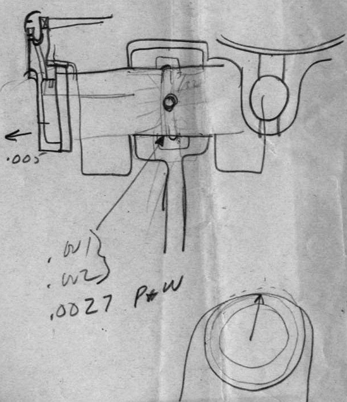 |
| Blackwood's Connecting Rod Sketch |
26 Dec 1946. A few pages of Blackwood's notes appear to have been taken during a telephone call. They indicate that after 11 hrs endurance running an engine inspection had revealed metal pieces in the oil sump. One piston pin was seized to the link rod, but was free in the master rod. The surface of another link rod had defects in the silver plating at the knuckle pin. There was room in the connecting rod for a 0.030" wall piston pin bushing and knuckle pins were available from Mallory in 48 hrs. A further note, "Check R-2800 Service Manual" probably referred to P&WA instructions on re-plating knuckle pins. Lycoming planned to try silver-lead-indium first, and would also probably make a new rod set with bushings.Blackwood included a sketch of the master rod, link rod and link pin in cross section. More notes concern P&WA master rod, link rod and link pin part numbers and rework instructions. A further page of notes concerns R-4360 connecting rod design, component rework procedure and dimensions.
The 3-cylinder engine was running with a new-design link pin retainer, which was working well. The same part had been used on XR-7755 #102. The third parts set was 70% or more complete. The 0.56 reduction gear would be ready in a week and could go onto #101. The torquemeter in #101 was experiencing excess oil leakage and was being revised. [Penciled notes by J.G. Blackwood. RG 342 RD2311 XR-7755, 1943-1948 = 503-602 Conf and Tel Notes.]
Send mail to
![]() with questions or comments about this web site.
with questions or comments about this web site.
![]()