
The Lycoming XR-7755
Working Topic 1945
by Kimble D. McCutcheon
|
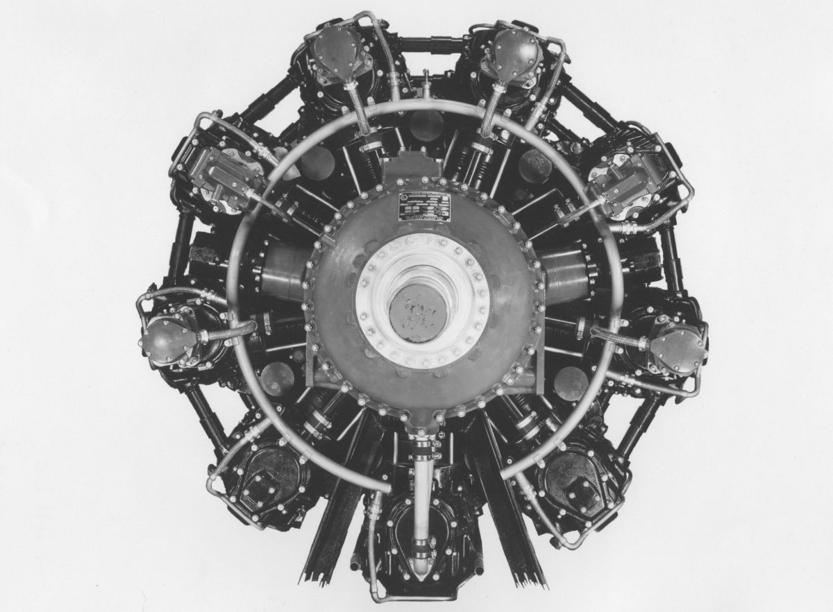
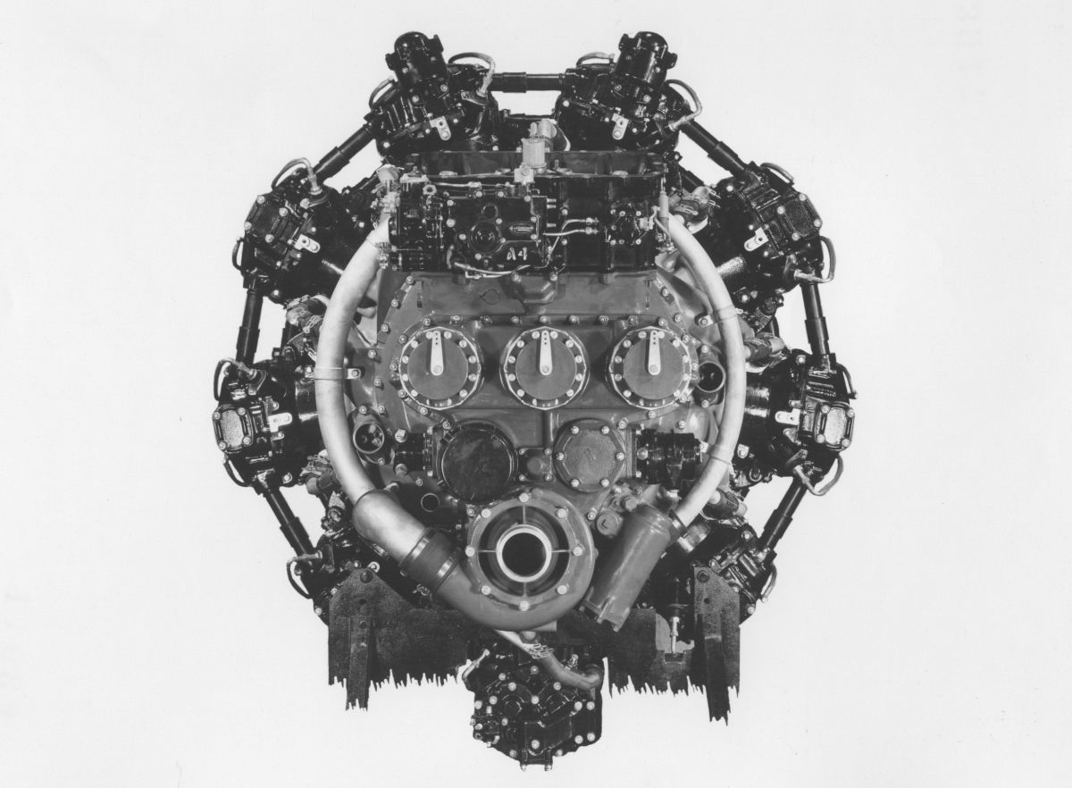
| XR-7755 Engine Mounting Details |
1 Jan 1945. Aircraft Laboratory civilian employees H.A. Magrath and G.L. Getline issued Memorandum Report TSEAL-2-503-2, Aviation Corporation Report No. X-661 Regarding the Anti-Vibration Mounting Systems for the Lycoming X-7 Engine. Report X-661, entitled "Lycoming X-7 Engine Mount Design Study," was originally submitted to the PPL on 9 Jun 1944 [RG 342 RD737. Lycoming X-7 Engine Mount Study Rpt X-661] and then forwarded to the Aircraft Laboratory. The report discussed two general X-7 mounting methods: one supported the engine in a manner similar to inline engines; the other supported the engine at its blower section and utilized a circular mounting ring similar to convention radial engines.
Three variations of the first method were explored: twin cantilever beams, a monocoque shell surrounding the engine, and a steel tube mounting truss. All of these schemes complicated the detailed cowling design, and produced excessively large and heavy cowlings. This method also interfered with engine component maintenance access.
The Aircraft Laboratory preferred the second mounting method. A Lycoming-proposed variation of this scheme used cylinder head attachments for weight loads and crankcase mounts for torque loads, but designing the engine mount to insure proper distribution of torque and weight loads was complicated. The most feasible approach used nine rubber vibration isolators between the mount ring and engine blower housing, which meant that the blower housing carried all loads. Report X-661 presented a blower housing stress analysis indicating that it was strong enough to transmit the loads, although the analysis was approximate due to the irregular structure analyzed.
The anti-vibration requirements for power plant installations as set forth in the Handbook of Instructions for Airplane Designers, Revision 7 (paragraph 101(a)(3) page 673) specified that vibration isolators be used to attach the power plant to the airplane structure. Since Lycoming was contemplating this mounting method and since service experience had shown that these mountings minimized transmission of engine-propeller generated vibration, Aircraft Laboratory concurred with Lycoming's plan.
These discrepancies did not affect the work result but were pointed out for the convenience of Lycoming. Aircraft Laboratory comments on Report X-661 would have been expedited if dimensions and other values appearing in the text had also appeared on Fig. 8 and additional diagrams. Similarly, indicating the formulae used in the text before numerical values were substituted would have improved the report's clarity.
The Aircraft Laboratory concurred with X-661 conclusions and recommendations, but suggested that additional data was desirable, especially for future engine-mount applications. Engineering data listed in paragraph B-5 was forwarded to the Aircraft Laboratory Dynamics Branch.
On 2 Feb 1945, Lycoming Chief Engineer S.K. Hoffman wrote the ATSC Aircraft Laboratory Director acknowledging receipt of ATSC's 1 Jan 1945 Memorandum Report TSEAL-2-503-2. Hoffman stated that the information requested in paragraph B-5 was then being prepared and would be forwarded when the necessary information was received from the Lord Manufacturing Company, a maker of elastomer vibration isolators. [RG 342 RD2081. R-7755 Mounting.][Penciled notes by J.G. Blackwood. RG 342 RD2311 XR-7755, 1943-1948: 503-602 Conf and Tel Notes.]
4-5 Jan 1945. Prescott visited Lycoming and reviewed drawings for parts ready for fabrication. He concluded that engine development had been delayed by approximately three months, but thought it still possible to complete a 36-cylinder engine during spring 1945. He suggested allocating funds for 3- and 4-cylinder testing in order to accomplish as much as possible in connection with the 36-cylinder.
Hoffman was told that sufficient drawings were then on hand for preparing presentation-grade picture drawings by ATSC. Lycoming had received a contract change notification permitting procurement of parts necessary for assembling 3- and 4-cylinder test engines, but no provision had been made to cover the costs for running these tests. Hoffman suggested that the specific 3- and 4-cylinder test programs be covered under existing test items, such as Contract Item 1 or 8v. However, Item 1 was unsuitable unless a due date extension was granted and Item 8v was unsuitable unless additional funds were allocated. As these vehicles were unsuitable, it was suggested that Item 2 Call 1 could be used for this purpose. (Calls were a contractual mechanism by which the Government could add deliverable items to the Lycoming contract. Each call consisted of one or more deliverable items, each described by a scope of work.) Further discussion indicated it might be desirable to issue Call 2 with specific provisions for this test program, which was essential to the overall engine development.
The 3-cylinder unit was to employ the crankcase front and rear sections, along with master and link rods of the latest design, duplicating as fully as possible the 36-cylinder design. Similarly, the 4-cylinder engine was to employ the entire 36-cylinder crankcase and crankshaft, cylinders, cylinder head and valve gear. Although Lycoming was being permitted to procure the necessary parts, it would be four to six months before the engines would be ready to run, which would allow time to prepare additional authorization to cover the test program. Hoffman stated that the new 1-cylinder head duplicated to the extent possible the multi-cylinder head construction and would be on the test engines in the near future.
Prescott examined a partially-completed XR-7755 mockup. The cylinder barrels were of wood, but dummy cylinder head castings had been made. The pattern labor cost did not exceed the cost of making a wooden dummy head and the additional eight castings were far less expensive that eight more wooden dummies. The crankcase, rear accessory and supercharger sections were of wood. The reduction gear sections remained to be completed.
The BX engine was operating on a torque stand with dual-rotation propellers and generating information on the reduction gear and propeller performance relative to the XR-7755. Connecting rod fatigue testing had revealed that the 1.250" knuckle pins were too small, so their diameter was being increased to 1.375". It was also found that oil holes oriented within the high stress plane led to pin failure while no failures occurred if the oil holes stayed in the neutral plane. This indicated that knuckle pin rotation had to be prevented. No method had evolved using an end seal construction with pin locking provision. Changes were being laid out and were to be tested on the 3-cylinder rig.
Lycoming proposed an engine lifting scheme that replaced the forward propeller nut with special lifting eyes capable of lifting the entire engine weight in a crankshaft-vertical orientation. The engine rear was to be handled using wire rope slings instead of lifting lugs. Most large radial engines were equipped with lifting slings that that balanced the engine on its lifting hook with the crankshaft horizontal. Lugs on two or more cylinder heads prevented potential damage resulting from torsion loads applied to a single cylinder head. A complete sling provided with each engine allowed it to be installed in an airplane.
Prescott reviewed two-speed dual-rotation and single-speed single-rotation reduction gear layouts. Hoffman stated that a simple adapter coupling would be made so that the multi-cylinder engine could be operated at reduced speed without the reduction gear actually installed in the nose case. The adapter would facilitate development testing even if it were necessary to remove the reduction gear and make extensive changes.
Lycoming described a problem it was having with Aero Thread and Helicoil inserts. A go/no-go gauge for the tapped holes in aluminum housings gave satisfactory thread inspections before the inserts were installed. After insert installation the go gage would not enter some of the threads. However, the fastener would successfully thread into the insert. Lycoming requested information from other manufacturers' experience. Lycoming was hesitant about continually accepting parts by deviation and was planning to expand the inserts using a special custom hardened ground tool that would set the insert firmly after which the go/no-go gage would properly inspect the holes.
For the cap screws that held the crankshaft together, an alternate 18-pitch Whitworth thread form had been fabricated and tested in comparison to the round-wire Aero Thread. The only objection to the Whitworth thread was the very small rood radius. Prescott suggested that a modified USF thread with considerably increased flats on the thread tops and large root fillets might be desirable in this connection. It was decided that at least one alternative thread design would be provided. The round-wire Aero Thread inserts had been unacceptable when the testing was carried to destruction. However, this was an extremely unusual test condition that would not be encountered during normal crankshaft operation. A final decision would not be reached until the crankshaft joint testing machine was complete and a testing program on the crankpin joints conducted.
[16 Jan 1945 Memorandum Report TSEPL-5-503-4059. R-7755 Engine, P282577.]
Hoffman stated that the short-stroke single-cylinder running had exceeded the 500 hrs specified by Call No. 1, but that the allotted funds had not been expended and suggested continuation in view of the additional data this engine's operation could provide on piston, rings, cylinder head, valves and valve gear. It was agreed that continued testing was desirable. The single-cylinder X-2 engine was no longer in operation, and the Item calling for this testing was incomplete. Hoffman suggested that further short-stroke X-7 single-cylinder operation be substituted for the remaining X-2 test time. Prescott suggested that Lycoming forward a letter to the ATSC requesting the substitution.
The XR-7755 mockup was examined. It now included all of the cam boxes, cylinders, crankcase, accessory case and rear supercharger inlet. The nose section mockup was in process and would soon be installed. Cam box covers would be made from multi-cylinder cam box cover castings, and photographs of the mockup would be available in the near future.
The disassembled two-speed reduction being tested on the XH-2479-7 was examined. Some wear was evident on the clutch teeth and this was attributed to faulty operation of the balk ring, a defect that was being corrected. Additional shifts were scheduled. To date this reduction gear had approximately 400 gear ratio shifts on the dynamometer and 32 on the XH-2470-7 engine.
Engine parts then being fabricated and also finished parts received from vendors were examined. Steel crankcase sections were being machined from forgings. Connecting rods were also being machined and were to be subjected to fatigue testing in a special fatigue test fixture utilizing rotating unbalanced weights. Forgings and machined crankshaft segments were examined. The latest supercharger impeller design was examined and it was noted that the angular position of the impeller vanes gave the impeller a slight backward discharge characteristic, which was thought to improve supercharger operation over the required airflow and impeller speed range.
Previous correspondence indicated that Lycoming wanted to overhaul XH-2470 engine No. 103 and make it available for use on Contract No. W-33-038 ac-564 to run in the new dynamometer equipment, thereby saving the XR-7755 while getting the dynamometers into operation. Engine No. 103 was a spare engine for the Vultee XP-54 flight test program. MatCmd suggested that perhaps another engine could be made available for running in the dynamometer equipment.
Prescott asked about the X-7 expenditure reports covering the period from 1 May 1944 to 1 Sep 1944; Lycoming was to forward these reports to the PPL to complete the project records.
The Propeller Laboratory had requested a design layout for a reduction gear with a 0.2 ratio adapted to a 28-foot diameter propeller. Lycoming, having insufficient information about this requested a letter from the ATSC stating the specific requirement; it was reluctant to pursue such a design until the X-7 project was further along.
Prescott requested test data showing the friction found in the nose-to-nose reduction gear tests. This was a Navy project, but Hoffman stated that reports were in preparation and that the ATSC was on the distribution list.
Prescott inquired as to the use and test results of AN-F-33 fuel and the available of this fuel for tests. Hoffmen stated that the fuel was on hand and that tests were scheduled on two special fuels. One was the S-4 reference fuel of which 600 gallons was available; the other was AN-F-33 fuel purchased through the Cooperative Research Council, of which 2,000 gal was available. Lycoming planned to use Sperry detonation detection equipment to determine detonation limits.
Simulated altitude tests were being conducted by throttling the inlet of the pumps to obtain altitude performance of coolant and oil pumps. The ATSC had information about National Carbon Company coolant pump tests and these were available to aircraft engine manufacturers. MatCmd suggested the Lycoming obtain copies from the National Carbon Company.
The previous difficulty encountered in installing round-wire Aero Thread inserts was discussed. This process had been greatly facilitated by threading the entire inner surface of the hole in the crankshaft, thereby permitting the insert to be inserted into the thread at the open hole end. Pull tests results were so good that Lycoming wanted to use these inserts if the assembly difficulties could be overcome. The obvious advantage was the large fillet radius in both the crankpin and the bold, reducing stress concentrations and fatigue failure danger. A secondary advantage was the ability to replace a damaged thread insert. It was previously thought desirable to have an alternative thread system available, but if the assembly difficulty was overcome, the alternative design would not be necessary. [26 Jan 1945 Memorandum Report TSEPL-5-503-3069. Conference on Lycoming R-7755 Engine, P320999.]
 |
 |
 |
 |
 |
 |
 |
A connecting rod test fixture using rotating weights for loading was discussed. The crankpin joint test machine was being fabricated. Sufficient clearance for the 6.375" diameter generator was verified. Modifications of USF threads were discussed as a possible alternative for the round-wire Aero Thread inserts in the event the assembly difficulties were not overcome. ATSC wanted a weight estimate for a 0.2 reduction gear adapted to a 28-foot propeller. [10 Feb 1945 Memorandum Report TSEPL-5-503-3077. Conference on R-7755 Engine, P320956.]
19, 20 Feb 1945. Prescott visited Lycoming for more drawing releases. Lycoming reported that the 0.2 reduction gear would weigh roughly 750 lb. It would be four months before Lycoming engineers could undertake the design.
The connecting rod test machine incorporated rotating weights that were adapted to testing the master rod and one link rod under fatigue stress conditions. The machine was to be fabricated from steel plate and driven by a variable speed motor.
Prescott examined various full-scale engine parts, including the forged steel crankcase and crankshaft sections. A test sample of the Gleason curvic crankpin joint had recently been received for the crankshaft joint testing machine, which was projected to be ready in another 30 days. The test specimen exhibited no sharp corners and its construction was deemed excellent.
Prescott estimated that almost all major assembly and detail drawings were in order for release. About 75% were already fabricated or in process. [27 Feb 1945 Memorandum Report TSEPL-5-503-3089. Conference on R-7755 Engine, P320907.]
All parts contacting the fuel were required to give satisfactory performance on PPF #45-4. Carburetor parts, such as diaphragms, were to be tested with 75% PPF #44-56 plus 25% PPF #44-55 at a minimum. Due to the fact that xylidine as unevaporated heavy fuel ends traveled along induction system walls, its concentration could be significantly higher that the concentrations present in PPF. The ATSC recommended testing intake manifold components with PPF #44-56 at the approximate working temperature of the part under test. The ATSC recommended that all oil cells, oil hoses and other rubber-like parts in contact with the oil give satisfactory performance with 70% AN-VV-O-446a lubricating oil, Grade 1120, plus 30% by volume PPF # 45-4. This diluted oil would contain 12% total aromatics and 0.3% xylidine. The ATSC requested that Lycoming perform these xylidine sensitivity tests under Paragraph 14 of Item No. 12-4 of Exhibit 1 to Contract W 33-038 ac-563.
5, 6 Mar 1945. A conference held at Lycoming between Messers Hoffman, Carpenter Ryder and Bevan of Lycoming and Lt Shippely, Messers Littman and Blackwood of the ATSC. The group observed engine development progress, the 36-cylinder mockup and 36-cylinder parts in various stages of machining. The tentative Lycoming Specification No. 2020, undated, which was based on the AN Specification C, was discussed before submission of an official copy to the ATSC. This specification covers a single-speed single-rotation engine with a 0.56 reduction gear ratio for development purposes, and will supersede Lycoming Model Specification No. 2020, dated 16 Jun 1944.
The Lycoming nose section layout using a No. 80 front nose section and a No. 70 propeller shaft for torque stand test of the first XR-7755 engine exhibited no interference for the two sizes.
Under the terms of Item 12-7, Exhibit 1 of the subject Contract, Lycoming recently conducted a weight study to determine the reduction gear weight requirements stated in the 17 May 1944 letter to Lycoming covering a single-speed 25-foot diameter propeller. This would require a reduction gear ratio of approximately 0.2. The study was desired by the ATSC in order to get an approximate comparison of weights between single- and dual-rotation reduction gears, both suited for optimum propeller operation up to 40,000 ft. Letter report on this brief study was to be submitted by Lycoming. The single-rotation two-speed reduction gear would weight about 750 lb..
In accordance with ATSC discussion on application of this engine class to an airplane, some possibility exists of making a buried-wing installation of the Lycoming engine in which case an extension shaft to the propeller would be needed. Since this matter is not pressing, no steps were to be taken at the time. However, a study of the extension shaft application might be initiated later as a call to the subject contract to cover such a possibility.
Lycoming was to revise its curve No. 4217 incorporated in report No. X-647, which showed estimated multi-cylinder sfc at maximum economy for various powers and speeds. This revised curve was to be based on the latest single-cylinder performance data of the multi-type cylinder.
Multi-cylinder engine parts were being received and machined. It was anticipated that parts for the first engine would be available by June 1945. A Call Item to subject contract covering the building of the first two engines and preliminary testing up to the point of acceptance tests was therefore to be initiated in the very near future. [12 Mar 1945 Memorandum Report TSEPL-5-503-3095. Contract W-33-038 AC-564 Lycoming XR-7755 Engine, P320889.]
8 Mar 1945. Lycoming Chief Engineer Samuel Kurtz Hoffman, in a 5 Mar 1945 conference with J.G. Blackwood pointed out that these tests were not easily accomplished on the single-cylinder engine (Item 12-4) and suggested that these tests be confined to the Materials Laboratory until a multi-cylinder XR-7755 was available. He further suggested that it would be helpful if the ATSC could supply a list of materials that had been approved for use with the subject fuels. Col Keirn concurred in a 26 Mar 1945 letter, but also said that no list of approved materials yet existed and suggested that materials being contemplated for use be checked with the subject fuels. [RG 342 RD 2311 XR-7755 Contract W-33-038AC-564 Authorizing Correspondence]
[RG 342 RD 2311 XR-7755 Contract W-33-038AC-564 Authorizing Correspondence]
22, 23 Mar 1945. Prescott traveled to Lycoming to discuss detonation limits on old and new cylinders and to release drawings for fabrication. The first cylinder design was found, by means of temperature-sensitive paint, to be more uniformly cooled than the latest design. However, operational tests with additional coolant flow did not show improvement. The detonation limit, as determined by a special pickup was lower than that of the first head design. The only major change was the spark plug location; the first design had the plugs about 6" apart and located in a plane about 35° – 40° from the valve plane and cylinder axis. The second design had plugs about 4.5" apart, on the fore/aft cylinder axis. The detonation pickup was located about 35° – 40° on the opposite side of the valve plane and was the same in both old and new cylinders. Obviously, the relation of the pickup to the spark plug positions was considerably modified. Another change was in the intake port placement. The old design intake ports were inclined about 15° to the valve plane; the new design was in the valve plane, a change that destroyed the swirl tendency of the old design. This may have affected the detonation limit. However, intake port modifications were being made to the new design to create swirl in an effort to improve the detonation limit. It had been suggested that perhaps the revised spark plug location made the detonation detector more sensitive. Lycoming engineers were checking this.
During a previous visit, ATCS personnel had suggested t hat sodium-mercury valve filling be tried in comparison with metallic sodium as a valve coolant. Lycoming engineers stated that valves were on hand with both fillings for comparative tests.
A study had been made of the variation in valve timing caused by placing all four master rods in different locations. This showed the possibility of timing improvement by timing each camshaft for best average valve timing. [31 Mar 1945 Memorandum Report TSEPL-5-503-3104. R-7755 Engine, P321158.]
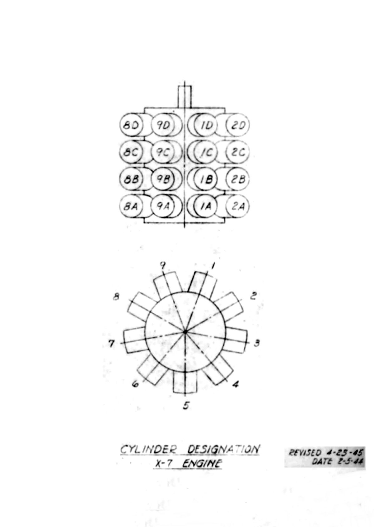
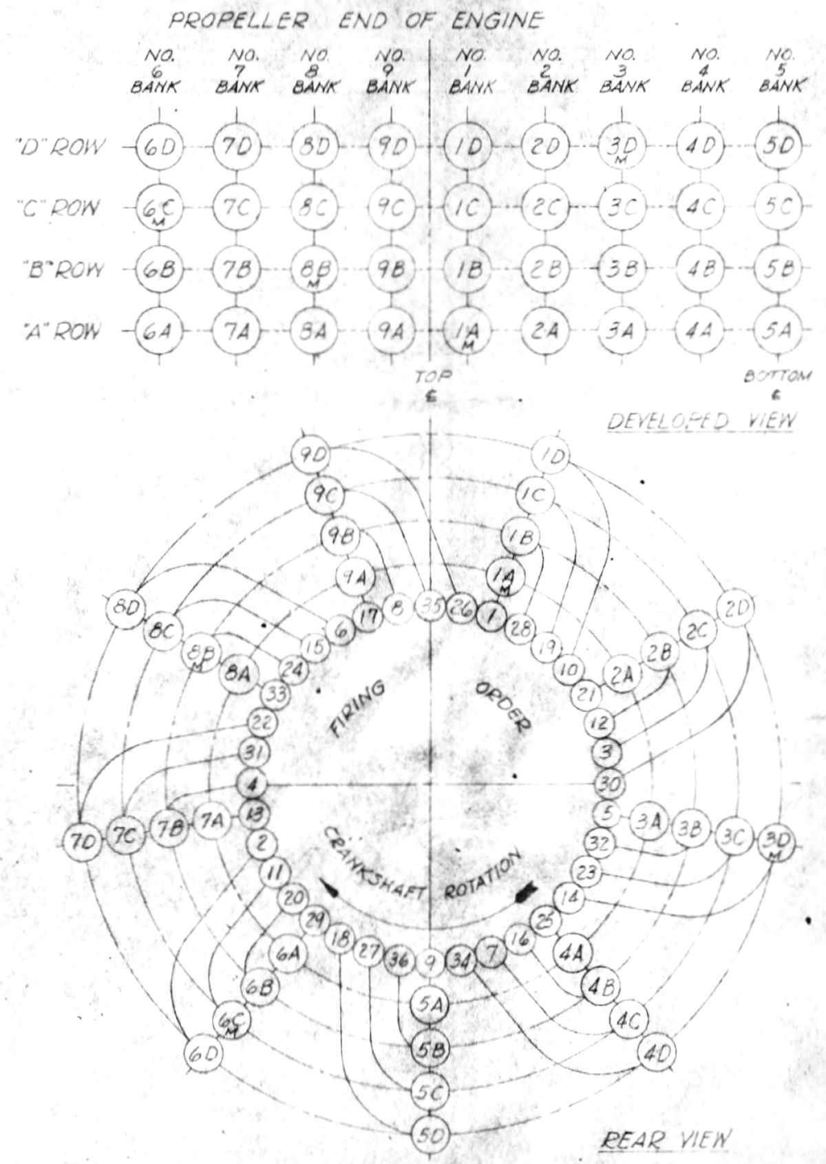
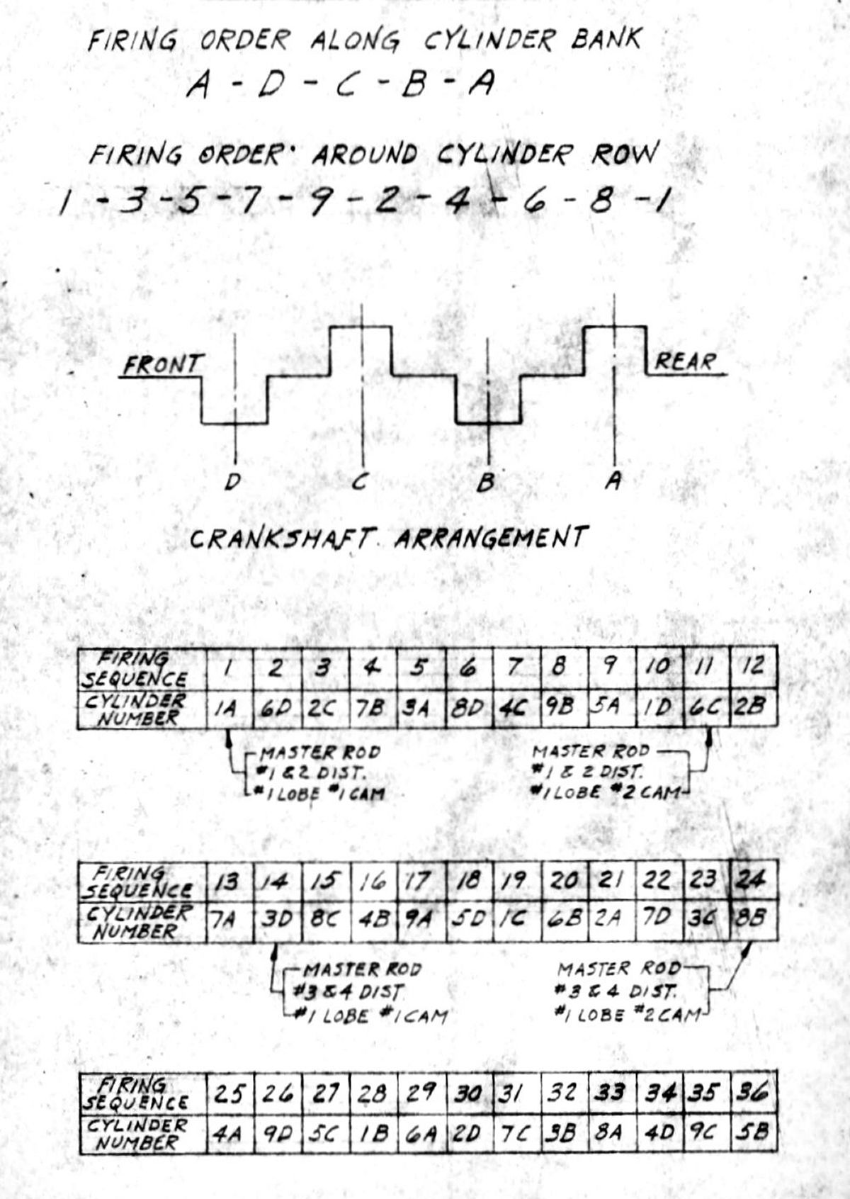
19 Apr 1945. Lycoming's J.H. Carpenter, following up on a Wright Field request, issued drawings defining the X-7 cylinder numbering and firing order. The cylinders in each of the four rows were numbered clockwise as viewed from the rear, with cylinder #1 of each bank being at the top-right of center. Each four-cylinder bank were lettered A through D, rear to front. [J.G. Blackwood Notes. RG 342 RD2311 XR-7755, 1943-1948: 503-602 Engineering Data.]
 |
 |
 |
| Lycoming X-7 Cylinder Numbering and Firing Order | ||
23-25 Apr 1945. Prescott visited Lycoming to review the remaining XR-7755 detail drawings not yet released. The first engine was expected to be assembled about 1 Jul 1945. Earle Ryder complained about the difficulty that had been experienced in getting dynamometer equipment for the test laboratory. The building was expected to be ready about 1 Jun 1945 and the dynamometer was urgently needed if the XR-7755 program was to stay on schedule. The ATSC agreed to expedite dynamometer delivery to the extent possible. Original delivery had been promised for May 1945, but that date had been pushed to October.
Prescott examined parts in process as well as those in the stock room. Rapid progress had been made. Since the first engine was to be a special single-shaft test engine, some of the two-speed dual-rotation drawings were yet to be released. Lycoming projected that all parts for the first engine would be complete by 1 Jun 1945, after which the first engine's assembly would be completed during June.
The mockup engine was not yet complete, but the dual-rotation reduction gear wooden model had been installed. The main item still lacking was the cam box cover mockup. Lycoming intended to machine and install eight standard cylinder covers for this purpose, as well as replacing the wooden supercharger section with an actual partially-machined (possibly defective) casting.
The largest casting received thus far was the supercharger housing and engine mount casting, which was received on 25 Apr 1945. It was to be immediately processed by the machine shop together with the crankcase section incorporating the cam drives at the engine forward end. Both of these casting were in the process of checking and laying out preparatory to machining.
Prescott examined the supercharger performance test setup, which was driven by a large DC motor deriving its current from an AC-DC motor-generator set. Slight difficulty had been encountered with the impeller thrust bearing, but work-arounds were being incorporated.
Prescott also examined the crankshaft test rig. This was being assembled and crankshaft fatigue tests were planned for the near future.
In addition to those parts previously released, the foregoing drawing list constitutes almost everything required for a complete engine. The propeller thrust nut design was discussed; this nut incorporates gear teeth for a special spanner wrench to install the nut. Prescott volunteered to investigate whether any existing standard might simplify the tool problem in the overhaul shop. He found that no No. 70 wrench was in use and that there would be no objection to using gear teeth for the propeller thrust nut. [28 Apr 1945 Memorandum Report TSEPL-5-503-3126. Conference on R-7755 Engine, P321325.]
4 May 1945. Blackwood prepared a report on XR-7755 program progress for Gen Carroll and took the opportunity to recommend that aircraft manufacturers be contacted to understand their future needs for very high-power engines with very low fuel consumption in aircraft the size of the Convair B-36 or larger. Blackwood dedicated several paragraphs to describing the engine and its development history. He attached the latest version of Lycoming's XR-7755-1 Model Specification No. 2020 and an installation drawing. He also explained that the XR-7755-1 was primarily intended for testing and that the XR-7755-3, with its two-speed dual-rotation reduction gear was to be the first flight model.
The two-speed dual-rotation reduction gear was to be tested independent of the engine by 1 Apr 1946. A large portion of multi-cylinder engine parts, enough for three complete engines and one set of spares, were finished; the remaining parts were either in process or on order. The first XR-7755-1 was expected to be built in August 1945. Testing on the propeller test stand was to begin immediately after the engine was assembled. Due to delays in delivery of the new dynamometer equipment, performance and calibration tests would not be made before January 1946. Blackwood predicted that, barring complications, the first XR-7755-3 flight engine should be available for flight in late 1946. Since all current engines were slated for experimental development, additional engines would need to be procured for aircraft installation. The engine had been designed for nacelle installation, but an extension shaft design could be provided later by a contract amendment of so desired.
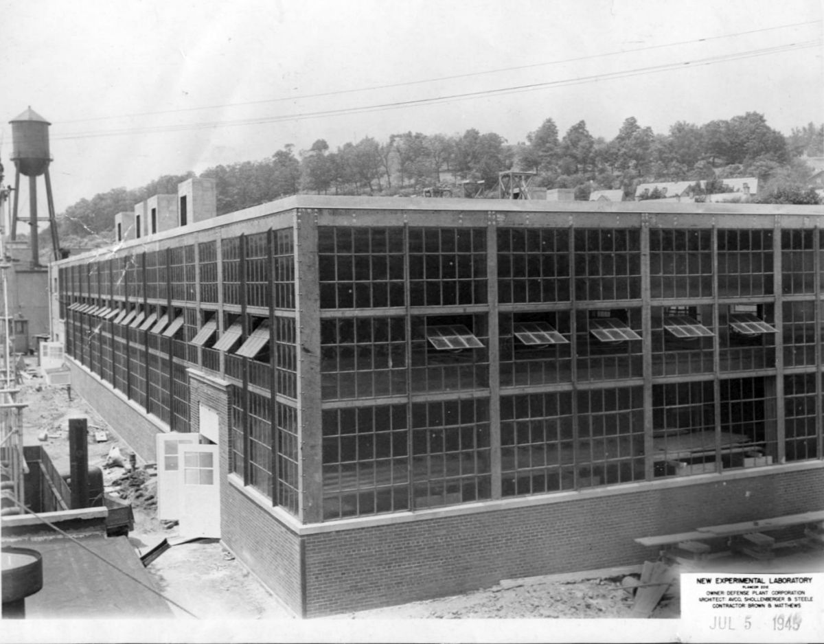
The new building's progress was satisfactory. It was to house the new 36-cylinder engine dynamometer, 1-, 3- and 4-cylinder test engines and their dynamometers, an assembly room, and special test rooms. The Lycoming engine-propeller test stand was being reworked to accommodate the XR-7755; this work was expected to be complete by July 1945. Equipment transfer and setup would probably also start in July 1945.
Since the project started in July 1943, $3,651,575.00 had been obligated to it. Based on previous estimates, $1,000,000.00 to $1,500,000.00 would be required for FY 1946; Lycoming would submit its proposed procurement in June or July 1945. [Penciled notes by J.G. Blackwood. RG 342 RD2311 XR-7755, 1943-1948: 503-602 Conf and Tel Notes.]
[J.G. Blackwood Notes. RG 342 RD2311 XR-7755, 1943-1948: 503-602 Engineering Data.]
Lycoming had overrun the allocated test hours, which had been the subject of an ATSC letter dated 8 Jun 1944. All parties had understood that the hours stated in the contract were approximate, but Blackwood made it clear that in the future, Lycoming should request an extension prior to expiration of the contract time. Monthly cost analysis reports were to include an "inventory of parts" Item starting with the next report so that all costs would be included in the report. Cumulative item totals were being compiled since the contract was initiated. The first engine had 60% of its parts completed and in the Government Bond Room. The remaining parts were expected to be available during the first part of August 1945, permitting assembly of that engine during late August. The most critical items were cylinder heads, air inlet housing, sump and oil filter housing. The cylinder heads had been problematical because the aluminum alloy 142 did not cast well. Alloy 142 was a heat treatable aluminum casting alloy recommended for services at elevated temperatures. It had high strength and good wear resistance in the fully heat treated condition. However, it was primarily used for air-cooled cylinder heads and pistons, which might explain the difficulty with casting liquid-cooled cylinder heads. Alloy 355, which contained 5.0% silicon, 1.3 % copper and 0.5% magnesium, had been substituted but it was presenting machining difficulties. Parts for the 3- and 4-cylinder test engine were to be available in early August; these engines would likely be ready to run before the 36-cylinder engine due to simpler assembly.
Lycoming had revised the XR-7755-1, -3 and -5 model specifications IAW with the ATSC's latest comments; several markings and clearances had been omitted from the installation drawings. Lycoming had repeated the supercharger tests and the results checked with the original test within test limits. Adiabatic efficiency ranged from 74% to 78% over the operating range, indicating that further improvement might be possible. Operating Q/N value was slightly to the left of the efficiency curve (on the pulsating side) so that a diffuser change was being made to bring the operating Q/N value to the peak or slightly right of the peak efficiency curve. The coolant pump was available, the test setup almost complete and testing was to begin in a few days.
Fuel consumption values had been high during test engine endurance operation, except for that listed in Lycoming Report 869. Lycoming representatives replied that operation had been at best economy fuel/air ratio, but because shiftable camshafts and spark plug timing devices had not been available, takeoff spark and valve timing had been used. In addition, the 1-cylinder test engines had a 200°F induction air temperature, which the Lycoming engineers thought representative of the 36-cylinder engine, with its attendant pressure losses and sub-optimal supercharger efficiency. Lycoming was to provide the ATSC a copy of the air temperature versus manifold pressure curve then in use during testing.
Lycoming reported that the connecting rod test machine housing was available and that the remaining parts were almost ready. A propeller (test club) for the first XR-7755-1 engine would be needed by 1 Sep 1945; Blackwood agreed to look into its status. A GFE dual-rotation propeller would also be needed for loading the XR-7755-5 about June 1946.
The building to house the large dynamometer, single-cylinder test blocks and special test rooms was progressing well. The basic building was complete, although the cement floor was still being poured and interior finishing, plumbing and wiring remained. Lycoming expected to begin moving test equipment about 15 Jul 1945. The old propeller test tunnel had been modified to furnish adequate oil and coolant capacity, and strengthened to handle the XR-7755's output. The stand was to be ready during July 1945.
The XR-7755-3 mockup was complete except for spark plug blast covers, ignition harness, oil drain tubes, main oil feeder line, and coolant ring and distribution lines. Lycoming predicted that it would be available for photography in about a week. [21 Jun 1945 Memorandum Report TSEPL-5-503-3160. Contract W-33-038 ac-564, Lycoming XR-7755 Engine, P320035.]
26, 27 Jun 1945. Prescott visited Lycoming to help Lycoming representatives with drawing releases. He also reviewed the 1-cylinder test programs, along with 36-cylinder engine. The 36-cyllinder mockup was nearly complete. Delivery of the ignition harness, coolant and oil drain tubes was expected during early July 1945, at which time photographs of the mockup engine were to be forwarded to the ATSC. The mockup was to be supported by the same means as the Lycoming X-7 and presented a very clean appearance. R-7755 castings comprising the R-7755 rear mount pads were made of wood, but a partially-machined casting as used on the XR-7755 was to be installed as soon as available. This casting would make possible supporting the mockup in the same manner as the completed engine.
A copy of the design study in which the six P&WA engines were compared to the four XR-7755 engines was examined. In the study the two right- and left-hand engines were located in tandem, the forward engines being tractors and the aft engines pushers. This arrangement gave opposite rotation to the front and rear propellers. A study indicated that the overall aircraft weight was increased by 1.5%, the power increased by 11%, the range increased by slightly more than 11%, and the takeoff run reduced by 10%.
Prescott examined the design drawing covering a hydraulic loading device for testing two dual-rotation reduction gears. A circular case with internal vanes was used to twist a central shaft that applied loads top the two reduction gears internally. By this means loads could be applied after the reduction gears were in motion and the power required was only a fraction of the two reduction gears.
Prescott examined the crankshaft bending and torsion test machine. This device preloaded the crankshaft joint sections ion torsion and in bending after which torsional impulses were fed in by means of a very stiff coil spring simulating the dynamic crankpin loading as nearly as possible. Tests had proven that the crankshaft bolts had been originally installed with too great a preload. These bolts were also excessively hard. Lycoming personnel stated that the 48 to 52 Rockwell hardness "C" was selected to secure the maximum physical properties of the bolts securing the joint. ATSC personnel related that the nearest know application of this joint type was used in WAC crankshafts. While Rockwell "C" harnesses from 32 to 36 were quite widely used, it was well known that connecting rod bolts exhibiting Rockwell hardness as soft as 23 had been used. However, these bolts were subject to thread seizure attributed to excessive softness. The use of soft material allowed the bolts to take a slight set, after which the stress was uniform over the bolt section. It was recommended that the XR-7750 crankshaft bolt hardness be reduced in consideration of these findings.
Prescott examined the coolant pump test setup, including all essential controls for simulating pressure drop and for measuring pump flow and pressure characteristics. Parts in the tool room and in fabrication were examined. These included a number of smaller parts, such as oil pump gears, link rods, master rods and a camshaft turning device in which a one-to-one drive located back of the tool carriage caused the tool to move in and out and generate the cam outline. This device served to rough the cams own to within about 0.050" of their final form. After this operation the cams were to be ground on a cam grinding machine using the proper master cams.
Lycoming's cylinder head casting experience was discussed. Much difficulty had been experienced with trying to cast cylinder heads using ALCOA No. 142 alloy. In consequence, Alcoa No 355 alloy was then being used. The latter alloy had a higher silicon percentage and flowed much better than the ALCOA 142 alloy, which was difficult to pour and chilled rapidly leaving unfilled perforations. Although ALCOA 355 castings were approximately 3,000 psi short of ultimate tensile strength available with ALCOA 143, the loss was not serious in a liquid-cooled cylinder whose temperature never exceeded 375°F. Similar difficulties had been encountered with experimental Wright Field castings. However, one difficulty remained; ALCOA 355 machining exhibited the tendency to start picking up, which resulted in surface roughness not encountered with ALCOA 142.
Lycoming expected to begin assembly of the 36-cylinder engine in August 1945 and preparation was being made to operate it in the propeller test cell as well as on the dynamometer equipment. [7 Jul 1945 Memorandum Report TSEPL-5-503-3168. To Confirm Visit of ATSC Representative to Aviation Corporation , R-7755 Engine, P321339.]
 |
 |
| Brochure | Engineering Laboratory |
20, 21 Aug 1945. Prescott visited Lycoming to address remaining items for the first XR-7755 engine assembly. A slight delay in assembling the first engine had been encountered because of securing completed crankshaft parts from the Gleason Works, Rochester, New York. Prescott recommended that all possible steps be taken to expedite release of the facility construction that was ordered stopped in the blanket order issued upon the fall of Japan. Details of the two-speed dual-rotation reduction gear were examined and released for fabrication. Prescott declared it to be in good order from the design and fabrication standpoint. The first engine was to use a special reduction gear incorporating a ratio suitable for dynamometer tests, which meant the two-speed dual-rotation gear was not required for the first test engine.
Prescott emphasized that every effort should be expended to simplify the two-speed gear ratio control system in view that four such controls would be necessary. A single control system made the reduction ratio shift a simple process of throttling the engine and passing the throttle control through a gate to the second throttle range where shifting was automatically accomplished. This did not allow for pre-selection of the ratio by the engine operator. A second system was discussed in which a pre-set control determined the gear ratio before the actual shift was accomplished. The proposed control system called for at least three control rods and one or two oil pressure lines from the engine to the control panel. Lycoming engineers continued to study a means by which the engine/operator controls could be minimized. The first crankshaft joint endurance test had been started with a total bolt load of 400,000 lb. This test was operated for 1.5 million cycles at which time the bolt load was reduced to 300,000 lb. At this load an additional 4 million cycles was accomplished. It was found that the test sample deflected excessively under the bolt loads. To reduce this deflection a spacer was installed in the joint center. This spacer was later found to be approximately 0.003" too thick. The test sample was returned to the Gleason Works for examination and possible changes in the curvic tooth outline. A second pair of test specimens was set up with a spacer exactly the correct thickness and with a bolt load of 300,000 lb. This setup was run through 2 million cycles, at which time it was examined and found cracked at several tooth roots. This raised a question as to the condition of the first test samples, and inquiries disclosed that the first test samples were also cracked. This all lead to suspicion of the curvic tooth hardening method and also the amount of bolt preload required for a successful joint. Test sample examination showed the teeth to be very hard but the teeth roots were as soft as the unhardened crankpin material. This was a bad condition in that abrupt termination of the hardened portion left a condition of initial stress that was almost certain to cause tooth failure. Two remedies were proposed: 1) Modify or eliminate the tooth hardening; 2) Drastically lower the bolt load to the lowest value that would prevent joint slippage during any operating condition. If the lower bolt load proved to be satisfactory, the bolt sizes would be reduced, thereby increasing the tooth area available opposite the bolts. This matter was considered to be of the greatest importance inasmuch as it determined the utility of the built-up crankshaft scheme. Consideration was also being given to moving the curvic tooth joint to the crankpin center instead of placing it at the end. This would result in a very great crank cheek rigidity increase in a situation that now results in a short crankpin portion. Lycoming engineers were making every effort to address this problem.
Prescott examined the proposed reduction gear test rig. Its drawings were complete and being checked. This rig would be used for the nose-to-nose testing so that each reduction gear loads the other and the driving motor supplied only the friction loss. Prescott examined parts being fabricated in the tool room. Many of the parts required for the first engine were complete. The remaining parts were being fabricated as rapidly as possible. He noted that all machine work thus far accomplished had been of a very high workmanship standard. A tour through the new building and test facilities revealed good thinking and planning, thereby obtaining maximum utility from the funds invested in the laboratory. Lycoming engineers and management were sparing no effort to move the project along as rapidly as feasible. [12 Sep 1945 Memorandum Report TSEPL-5-503-3194. To Confirm Visit of ATSC Representative to Aviation Corporation , R-7755 Engine, P321727.]11 Sep 1945. Blackwood calculated the following engine/turbosupercharger characteristics:
| Lycoming XR-7755 at 4,000 hp and 2,300 rpm | Turbosupercharger Overspeed at 39,900 ft | Turbosupercharger Rated Speed at 37,800 ft |
| Lycoming XR-7755 at 5,000 hp and 2,600 rpm | Turbosupercharger Overspeed at 38,200 ft | Turbosupercharger Rated Speed at 36,200 ft |
| Studebaker XH-9350 at 4,000 hp and 2,000 rpm | Turbosupercharger Overspeed at 37,700 ft | Turbosupercharger Rated Speed at 35,700 ft |
| Studebaker XH-9350 at 5,000 hp and 2,200 rpm | Turbosupercharger Overspeed at 32,100 ft | Turbosupercharger Rated Speed at 30,300 ft. |
[RG342 RD2311. XR-7755.]
Allison Contract W-33-037 ac-7191 Status
V-1710-E30 (V-1710-127) compounded with General Electric C-23 turbine at 3,200 rpm and AN-F-33 fuel.
| Altitude (ft) |
Manifold Pressure (inHgA) |
Nozzle Box Pressure (inHgA) |
Nozzle Box Temperature (°F) |
Turbine Power (hp) |
Fuel/Air Ratio |
Turbo + Engine Power (hp) |
Water-Alcohol Injection |
|---|---|---|---|---|---|---|---|
| Sea level | 100 | 68 | 1,730* | 650 | 0.0804 | 2,760 | Yes |
| 5,000 | 100 | 67 | 1,725* | 730 | 0.0808 | 2,770 | Yes |
| 10,000 | 100 | 66 | 1,725* | 810 | 0.0795 | 2,790 | Yes |
| 20,000 | 79 | 50 | 1,725* | 660 | 0.0791 | 2,170 | Yes |
| 30,000 | 60 | 36 | 1,650 | 500 | 0.099 | 1,500 | No |
| 40,000 | 41 | 25 | 1,630 | 375 | 0.089 | 1,050 | No |
| *Exhaust collector water cooling necessary at War Emergency Rating with water-alcohol injection; nozzle box temperature maintained at 1,725°F maximum. | |||||||
The single-stage V-1710-G1 (V-1710-97) with 9.6:1 blower ratio and 10.25" impeller diameter was mechanically connected to a General Electric B31 turbine to reduce bsfc. A modified Lockheed P-38 exhaust system and auxiliary stage supercharger less impeller with hydraulic coupling was used as a step-down to get a 7.589:1 turbine wheel to crankshaft ratio. At 19,000 ft and 2,700 rpm the bsfc was 0.40 as compared with 0.475 for the V-1710-G1 at the same conditions. A maximum nozzle box temperature of about 1,825°F would have been reached at maximum cruise power (approximately 1,100 bhp at 2,700 rpm) if water cooling had not been used in the exhaust collectors. Nozzle box temperature was held to 1,720°F.
| Altitude (ft) | Manifold Pressure (inHgA) | Nozzle Box Pressure (inHgA) | Nozzle Box Temperature (°F) | Power (bhp) | Fuel/Air Ratio | bsfc (lb/hp/hr) |
|---|---|---|---|---|---|---|
| 2,700 rpm – Maximum Cruise Power | ||||||
| 19,000 | 41.3 | 40.3 | 1,725 | 1,040 | 0.0645 | 0.397 |
| 19,000 | 41.5 | 40.6 | 1,725 | 1,120 | 0.075 | 0.452 |
| 25,000 | 33.2 | 32.5 | 1,706 | 888 | 0.0645 | 0.402 |
| 25,000 | 33.2 | 32.5 | 1,642 | 845 | 0.075 | 0.440 |
| 30,000 | 27.5 | 27.2 | 1,660 | 708 | 0.075 | 0.415 |
| 30,000 | 27.5 | 27.1 | 1,546 | 718 | 0.075 | 0.475 |
| 2,200 rpm – Cruise Power | ||||||
| 19,000 | 30.0 | 26.4 | 1,588 | 457 | 0.0645 | 0.413 |
| 19,000 | 30.2 | 26.7 | 1,584 | 718 | 0.075 | 0.438 |
The first V-1710-E27 (V-1710-127) engine produced lower than expected power output. The auxiliary supercharger stage was improperly matched with the engine stage and was operating in a surge range; no further data was available. [J.G. Blackwood Notes. RG 342 RD2311 XR-7755, 1943-1948: 503-602 Engineering Data.]
18 Aug 1945. On 15 Aug 1945, Radio Tokyo broadcast a recorded message from Japanese Emperor Hirohito to the Japanese people announcing the surrender of the Empire of Japan. The U.S. Government almost immediately began shutting down most of the massive defense industry. On 18 Aug 1945, Blackwood received word from Joseph F. Heavey, the Philadelphia-based Director of Engineering for the Defense Plant Corporation (DPC) that all XR-7755 work was to stop immediately. The DPC, a subsidiary of the Reconstruction Finance Corporation (RFC), financed most new factories created to provide war materiel by financially supporting state and local governments, banks, railroads, mortgage associations, and other businesses supporting the war effort; it had provided partial funding for Lycoming's new test facility under Plancor 2212. The RFC, founded in 1932, was a government-sponsored financial institution that provided financial aid during the Great Depression and WWII. Plancor was a contraction of Plant Corporation, a designation used by the RFC to administer wartime plants. As many as 2,511 DPC Plancor facilities, designated Plancor 1 through 2511, were built.
Blackwood immediately set to work writing justifications for continuing XR-7755 work, and in particular, continuing test facility construction. He called Posthauer at Lycoming and requested detailed accounting of what was still to be completed and how much it would cost. In the mean time, Blackwood created a Routing and Record sheet on 20 Aug 1945 detailing that Plancor had allocated $983,000.00, $900,000.00 of which was committed. The large dynamometer was expected to cost $74,000.00, with an initial payment of $30,000.00. At that time the test facility building was structurally complete with electrical and plumbing work ongoing. Equipment installation was expected to commence in two weeks. [Penciled notes by J.G. Blackwood. RG 342 RD2311 XR-7755, 1943-1948: 503-602 Conf and Tel Notes.]
2 Sep 1945. Japan signed the official surrender documents ending WWII. Lycoming's Posthauer had provided the requested justification to restart work. Blackwood followed up with a more formal justification:
The importance of this facility was dependent on the importance of the XR-7755 engine development, Project MX-434, which was initiated in August 1943 and was required to provide a source for an engine type used in very large, long range aircraft where minimum sfc was of supreme importance. The need for such and engine was recognized much earlier in the 1940 Request for Data R40-D. The need for such an engine still existed for post-war aircraft development and no curtailment of Lycoming's development program was contemplated. Lycoming's progress and aggressiveness on the project was commendable and the first engine was expected to run in late September or early October 1945. Lycoming had maintained from the beginning that certain new facilities were necessary for this development; Lycoming's own facilities, which included utility generation, an experimental machine shop, refrigerated carburetor air source, a flight test cell and electric power substation, were being utilized whenever possible. However, Lycoming lacked the space and necessary equipment for this development in its current facility and consequently predicated its development undertaking on the premise facilities in the amount of $983,000.00 would be provided. This was approved under Plancor No. 2212.
WWII's end has not changed the need for the facility and the work stoppage has delayed development since certain testing could not be accomplished, and Lycoming would be unable to complete its contractual obligations without the facility. Blackwood requested that work on the facility be allowed to resume as soon as practicable. [Penciled notes by J.G. Blackwood. RG 342 RD2311 XR-7755, 1943-1948: 503-602 Conf and Tel Notes.]
30 Oct 1945. Lycoming Chief Engineer C.H. Wiegman wrote the ATSC, in reference to a 1 Aug 1945 Lycoming letter and the 15 Oct 1945 Lycoming Monthly Report No. 39-7, explaining the discrepancy between Lycoming Progress Reports and the AAF Representative's reports for Contract W 33-038 ac-564. Lycoming had reviewed all test reports and provided corrected data as of 15 Oct 1945.
| Item | Reported Time | Correct Time |
|---|---|---|
| 1 | 890.9 | 976.2 |
| 2 | 1,342.4 | 2,271.6 |
| 3 | 765.9 | 773.6 |
| 12-1 | 122.2 | 122.3 |
| 12-2 | 2,000.0 | 1,998.7 |
| 12-3 | 563.5 | 562.9 |
| 12-4 | 1,000 | 920.1 |
| 12-5 | 0.0 | 0.0 |
| 12-13 | 500.2 | |
| 12-14 | 191.8 |
Because the corrected time for Item 12-4 was less than the 1,000 hours called for by the contract, Lycoming requested permission to reopen this item and run the remaining 79.9 hours. This added time would not affect the original cost estimate. The 1 Aug 1945 Lycoming letter had requested that the contract be modified so that Item 3 called for 765.9 testing hours instead of the authorized 600 hours; the additional time request should have been 773.6 instead and Lycoming requested a corresponding contract modification. Similarly, the time requested for Item 12-3 should have been 562.9 hours.
Col Keirn was in agreement with all this and in a 13 Nov 1945 letter reported initiating corresponding contract changes. [RG 342 RD 2311 XR-7755 Contract W-33-038AC-564 Authorizing Correspondence]
1, 2 Oct 1945. Blackwood and Prescott visited Lycoming to review progress. Crankshaft joints as fabricated by the Gleason Works had introduced at least a 30-day delay in the first engine's assembly. Additionally, facility construction delays resulting from V-J-Day work stoppages had further delayed the project by 2 or 3 months. Blackwood and Prescott jointly recommended that that every effort be expended to expedite authority for further facility work in order to avoid further delay. Lycoming was attempting to install the ignition harness on the XR-7755-3 mockup in time for shipment to Wright Field for its exhibit on 12 Oct 1945; this was to be done by truck instead of train to insure minimum handling.
Finished parts in the Government Bond Room were examined, as were parts still in process. Lycoming engineers had found the individual cylinder heads and cylinder blocks, cast from ALCOA 355 alloy, entirely satisfactory; no difficulty had been experienced with machining. Multi-cylinder connecting rods were being completed; some were for the first engine while other were earmarked for fatigue testing. The first completely machined crankcase was examined and the machine work was found to be of a very high order. The crankshaft was now in the tool room for final machining. Its component parts had been processed by the Gleason Works where the curvic teeth had been ground. Flame hardening of the parts had been eliminated in view of the unsatisfactory fatigue performance. Crankshaft completion was expected around 2 Nov 1945. Pistons for the 36-cylinder engine were being machined up to the ring grooves. Accessory drive gears were partially complete. The combined supercharger and accessory gear housing appeared satisfactory. The casting was sound and machine work was almost complete. The recurring issue of supercharger inlet and housing airflow will be addressed later.
J.H. Carpenter stated that the nose-to-nose test fixture was to be release about 10 Oct 1945. The crankpin fatigue test machine was observed in operation, having completed about 4.5 million cycles at a 180,000 lb bolt load. No joint spacer was incorporated, which meant that the curvic teeth were carrying the load; no evidence of cracks had appeared in the teeth roots, which are now soft instead of the previously flame-hardened teeth. Torque variation had been reduced from ±50% to ±17%. This was considered to be ample since torque variation expected from the 36-cylinder engine less than 17%. The first run was to be made to 10 million cycles, after which the torque variation was to be increased to 30%. While there was a very slight of tooth surface galling, the parts were considered satisfactory for the present. "Thread Lube" was the only lubricant used on the curvic teeth; while this lubrication method was not as satisfactory as pressurized oil, Carpenter stated that all drawings for first-engine fabrication had been released.
The supercharger test rig program had revealed that air distributed to the nine supercharger housing outlets varied by about ± 8%. Distribution patterns indicated the presence of a lateral velocity vector due to the carburetor elbow at the supercharger eye entrance. Lycoming engineers planned to install and test two simple straighteners arranged to stop lateral air movement and direct it straight into the impeller. In order to secure the best possible inlet conditions a straight axial inlet was to be installed and the resulting distribution pattern was to be approximated as closely as possible by the previously-mentioned straightener vanes. Lycoming engineers were cognizant of the necessity to improve distribution in order to secure the required XR-7755 fuel economy. In retrospect it was obvious that the cylinders receiving the greatest air volume would develop the highest bmep while at the same time operating on the leanest mixture provided by the injection equipment that supplied a uniform fuel distribution to all cylinders.
The proposed semi-automatic hydraulic camshaft shifting mechanism was expected to unload itself once shifting was complete so that unnecessary camshaft bearing and shifting mechanism end thrust was avoided. The detonation study then under way was discussed, which promulgated a discussion on detonation theory and piston erosion, along with the cylinder pressure rise rate as affected by spark plug location. It appeared that the present location was advantageous since the charge burn rate was considerably greater with the new plug position.
Fuel injector pintle chatter was being experienced and Lycoming engineers were considering installing a damping orifice close to the injection nozzle that would relieve about 10% of the orifice pressure. It was thought that these orifices would considerably reduce nozzle pressure fluctuations caused by fuel compressibility and piping expansion between the pumps and nozzles. Lycoming engineers stated that this method had been used in some diesel engines and had already shown improvement in the nozzle discharger pattern.
While no hard schedule had been set for running the first engine, Lycoming projected December 1945. Lycoming Report No. 912, which reports the single-cylinder comparison of AN-F-28 and AN-F-33 fuels showed a 2% to 5 % increase in takeoff detonation performance, 1.5 inHgA less manifold pressure and 7% less isfc, approximately 15% to 25% increase in detonation-limited power for cruise operation and 2% to 4% decrease in best economy isfc for cruise. Obviously these advantages were important, especially those pertaining to better economy over a wider power range since this was the engine's prime objective. However, Lycoming was unwilling to revises its XR-7755-3 engine Model Specification No. 2031-A, dated 5 Jun 1945, to incorporate these improved performance data because multi-cylinder distribution and mechanical efficiencies were still unknown. It has since been decide by the ATSC that development should be proved with AN-F-33 fuel to gain those benefits, which should show up in the model specification later as multi-cylinder performance was obtained.
The performance of Contract W-33-038 ac-564 Item 1 was discussed. Lycoming Report 849 had been submitted with a letter of transmittal dated 27 Aug 1945 as completing this item. However, the full Item 1 requirements were not met by Report 849. Lycoming, therefore, submitted a letter requesting that the data of Reports 911 and 912 be also applied to Item 1. These reports were on later-design cylinders, and the performance values closely approach those required by Item 1 and were considered sufficiently close to the guaranteed values as to not warrant expenditure of further time and cost in approaching them more closely. A comparison of contract values for Item 1 and achieved values using AN-F-28 fuel follows:
| Imep (psi) | rpm | Equivalent (Multi-Cylinder (Power (bhp) | Contract isfc (lb/hp/hr) |
isfc Test Values (lb/hp/hr) |
|---|---|---|---|---|
| 231 | 2,600 | 5,000 | 0.59 | 0.59 |
| 155 | 2,200 | 3,000 | 0.36 | 0.35 |
| 141 | 1,600 | 2,000 | 0.333 | 0.34 |
| 1,000 | 0.344 at 116 imep and 1,000 rpm | 0.335 at 89 imep and 1,300 rpm |
Discrepancies in test conditions under which tests were run and covered by Lycoming Reports 889, 890, 892, 897 and 907 were discussed. In some cases best economy F/A ratio was not maintained during endurance running, improper mixture temperature was being used in several cases, and Report 889 continued several inconsistencies between tabulated and curve data. ATSC requested that these conditions be corrected in future operation; that corrected sheets be submitted for Report 889, and that airflow and F/A data and calibrations to show the best economy point be hereafter submitted.
Lycoming engineers stated that the test hours set up under Call No. 3 for 1-cylinder performance testing were almost exhausted, and submitted a letter requesting authorization for 200 hrs more testing. This was initiated and was to provide a stop-gap until the current procurement was processed for additional testing.
The propeller test stand was modified for the XR-7755's power and operationally checked with the Lycoming BX engine. The new building including the dynamometer equipment for testing the XR-7755 had been completed before the V-J-Day stop-work order. Much machinery was available for installation and some of Lycoming's test equipment was being moved from Lycoming's old buildings to the new building. Appreciable delay the engine development program was to be caused by delay in finishing this building. [16 Oct 1945 Memorandum Report TSEPL-5-503-3214. XR-7755 Engine, P322011.]
Send mail to
![]() with questions or comments about this web site.
with questions or comments about this web site.
![]()