The Lycoming XR-7755
Working Topic 1944
by Kimble D. McCutcheon
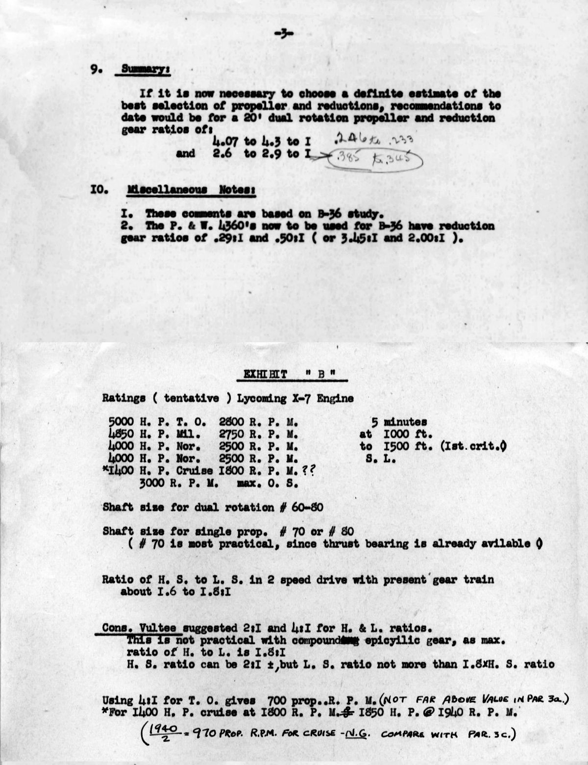
7 Jan 1944. Lycoming had decided to drop the X-6 engine configuration in favor of the X-7 four-row radial-nine. This was to have a 6.375" bore, 6.750" stroke and displace 7756.33 in³. Journal diameter was 4.250". Crankshaft and center section forgings were expected in one week. Thirty men were working in Experimental using four singles running two shifts with two men each. A single-cylinder casting was being made, and drawings had been released on a single-cylinder head, which was essentially the same as the multi-cylinder head. [Penciled notes by J.G. Blackwood. RG 342 RD2311 XR-7755, 1943-1948: 503-602 Conf and Tel Notes.]
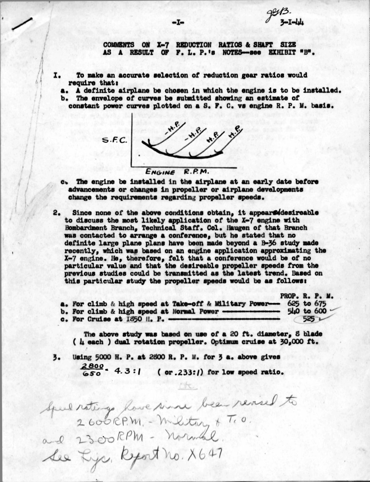
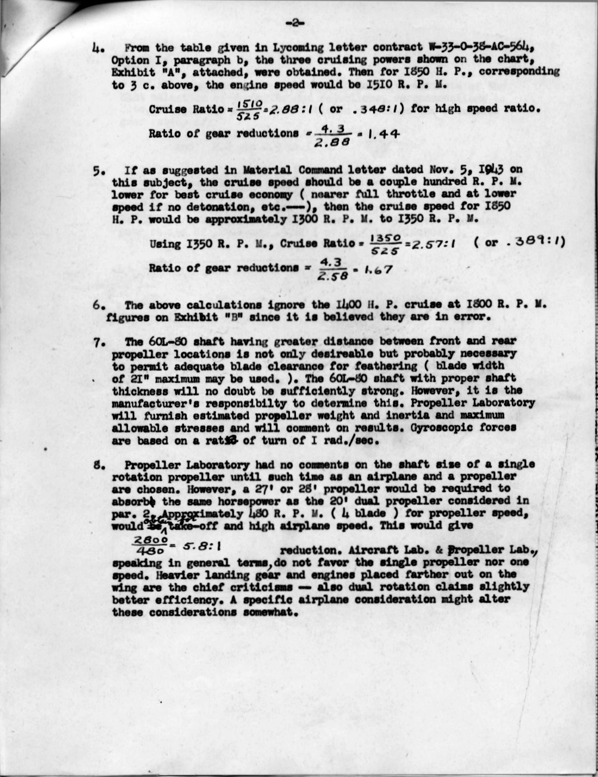
1 Mar 1944. Blackwood authored a white paper, "Comments on X-7 Reduction Rations & Shaft Size as a result of F.L.P.'s Notes—See Exhibit 'B'" that extended Prescott's work and explored the rationale behind ratio and propeller shaft selection. Lycoming produced some preliminary nose layouts intended to accommodate the various propeller combinations being discussed. [RG 432 RD2311. XR-7755 E.O. 503-602, Reduction Gear]
|
|
|
|
|
| "Comments on X-7 Reduction Rations & Shaft Size as a result of F.L.P.'s Notes" | ||||
 |
| Lycoming XR-7755 Nose Studies for Various Propeller Shaft Configurations and Sizes |
[Penciled notes by J.G. Blackwood. RG 342 RD2311 XR-7755, 1943-1948: 503-602 Engineering Data.]
3 Mar 1944. Blackwood compiled trade studies considering power per cylinder for a hypothetical XR-7755 delivering 5,000 bhp then and 7,200 bhp in the future.
Single-cylinder of a 5,000 bhp engine would need to deliver 140 bhp
Single-cylinder of a 7,200 bhp engine would need to deliver 200 bhp
A four-cylinder bank of a 5,000 bhp engine would need to deliver 555 bhp
A four-cylinder bank of a 7,200 bhp engine would need to deliver 800 bhp
A three-cylinder radial using 5,000 bhp engine cylinders would need to deliver 417 bhp
A three-cylinder radial using 7,200 bhp engine cylinders would need to deliver 600 bhp
A nine-cylinder row of a 5,000 bhp engine would need to deliver 1,250 bhp
A nine-cylinder row of a 7,200 bhp engine would need to deliver 1,800 bhp
| Engine | Bore (in) | Stroke (in) | 1-Cyl Disp (in³) | bhp |
|---|---|---|---|---|
| XH-2470 | 5.250 | 4.750 | 102.8 | 101 |
| BX | 5.375 | 5.375 | 122.0 | 120 |
| XR-7755, BX stroke | 6.375 | 5.375 | 171.6 | 169 |
| R-7755, standard | 6.375 | 6.750 | 215.5 | 212 |
[RG342 RD2311. XR-7755.]
6, 7 Mar 1944. PPL civilian employee Ford L. Prescott traveled to Lycoming Division, The Aviation Corporation in Williamsport, Pennsylvania to review X-7 drawings with Lycoming personnel. The proposed two-speed and single-speed reduction gear were discussed, as was feedback from several aircraft manufacturers. Two manufacturers opined that a single-speed design with a 0.25 ratio would satisfy all requirements for very large bombardment aircraft. Another wanted 0.25 low speed and 0.44 for high speed. Both designs were based on 22 ft 4-blade propellers. Lycoming's design was adaptable to both ratios.
However, some construction details required additional consideration. Lycoming proposed to divide the load passing from the planet gear sets to two internal ring gears, each of which was connected to torque-resisting pistons for loading the torque. Prescott criticized the overhung pinions engaging these because they were subject to excessive eccentric loads applied to a short taper, which Prescott thought would act like much like a spherical joint and permit the overhung pinion to become misaligned under load. Prescott also criticized the propeller shaft support, which would transmit undesirable lateral vibration from the crankshaft to the propeller shaft and fatigue the propeller blades. Prescott suggested two methods to eliminate this vibration transmission and Lycoming agreed to study the issue further. Another problem was that the engine was briefly disconnected from the propeller during shifting, requiring careful throttle control to prevent engine runaway. Lycoming pointed out that if the special double-cone synchronizing interlock were used it would permit engagement of the clutches only at synchronization. Prescott still thought that operation of such a large engine disconnected from the propeller would be problematical. Lycoming proposed a small auxiliary passage and throttle in the carburetor so that the no-load shifting would be completely handled with the main throttle completely closed. Lycoming stated that the XH-2470 engine, equipped with a similar two-speed gear, was to be tested in about 30 days and would provide further information on the shifting issue. The two-speed dual-rotation reduction gear is the same basic design as the single-rotation design. The dual-rotation design employed a second set of Gleason bevel gears operating like a differential gear to rotate the two shafts in opposite directions at the same speed.
Prescott examined the crankshaft design, which was nearly complete. It utilized a Gleason curvic tooth joint. (Note: this scheme was similar to the one Pratt & Whitney Aircraft employed on its three-piece C-series R-2800 crankshafts. The difference is that the P&WA design used a single large bolt where Lycoming proposed four smaller bolts.) The Gleason representative had objected to the long front crankshaft extension, which prevented grinding the curvic teeth until a new cutting and grinding head was made for the Gleason gear cutter, which was to cost $12,000.00. Further examination of the layout revealed that it would be feasible to redesign the crankshaft and propeller shaft bearing layouts in such a way as to eliminate the objectionable coupling between the crankshaft and propeller blades. If the new gear design proved feasible, it would permit cutting all crankshaft curvic teeth with existing equipment.
Methods of testing the crankshaft fatigue and torsional properties were discussed. Lycoming planned to construct a large flywheel at the crankshaft front and clamp equivalent inertial masses to the crankpins. This vibrating system would then be excited by motor-driven unbalanced weight attached to the flywheel, which would induce a severe torsional vibration.
The engine's rear section incorporated nine heavy mounting attachments, triangular in cross section, that were cast into the accessory section, forming very rigid engine mounting provisions. This casting included four supercharger outlet elbows connected to the four cylinder intake pipes. The engine mount itself was based on a design recommended by the Lord Manufacturing Company.
When he examined the supercharger and rear accessory section design, Prescott noticed that no provision had been made for the high bursting loads imposed on the supercharger by a backfire. Lycoming agreed to evaluate the introduction of long studs that passed completely through the supercharger section and provided ample strength against backfires.
Methods of connecting the individual intake pipes to the intake elbows were discussed. In this connection, it was planned for the carburetor to be installed as a down-draught angled 25° aft. Prescott questioned the limit of this angle in view of the added inclination due to climb; a 10° climb would induce a 35° total inclination. However, Bendix Products, the carburetor supplier, thought no difficulty would be encountered.
Lycoming engineers had drawn a coolant manifold that incorporated rubber sealed connections between the individual cylinders. These coolant manifolds were held in place by stainless studs passing through the fittings brazed in place opposite each cylinder connection. The hold-down cap screws were to be fully accessible with the intake pipes removed and it was considered possible that they would be accessible with the intake manifolds in place. The rubber joints between cylinders were to eliminate difficulties arising from unequal expansion of the cylinder block and manifolds.
Prescott examined the accessory gear box, which provided two vacuum pump drives, a generator drive and a power take-off drive. Also included was an oil pressure pump drive that provided a very short and direct oil passage in and out of the oil pump. A single starter drive accommodating a JH10E starter was planned, but MatCmd personnel thought a pair of starter drives might allow the two standard aircraft engine starters operating in parallel, which would be preferable to a single large starter. Lycoming was to consider this scheme despite favoring the single JH10E.
Lycoming inquired whether fuel injection equipment had been tested with the fuel passing through drilled holes in the supercharger impeller vanes, but Prescott was unaware of any such scheme.
A Lycoming engineer suggested the use of a high-pressure pre-oiling system for engine starting, a feature Prescott thought desirable.
The X-7 cam housing design was reviewed. These provided scallops for spark plug clearance, but this resulted in pockets on either side of the engine where oil could accumulate to a level where it would flow into the valve stem clearances. This was a serious fault when the engine was stopped or idling because oil could be drawn into the combustion chambers. Lycoming agreed to provide openings that would prevent valve stem oil flooding.
The necessary facilities for X-7 development were discussed. The Wright Field Facilities Branch was objecting to the $983,000.00 charge for build and equipping a test laboratory. Lycoming pointed out that the original contract price for the whole job was $1,200,000.00. This was reduced to $983,000.00 and Lycoming had agreed to assume all cost above $983,000.00. However, the Facilities Branch was unwilling to spend more than $600,000.00. This was a potential deal breaker for Lycoming and The Aviation Corporation, Lycoming's parent company, was in the process of making a final decision of whether to drop the entire X-7 development. [10 Mar 1944 Memorandum Report ENG-57-503-1171. Conference on Lycoming X-7 Engine, P281260.]
10 Mar 1944. A conference at MatCmd included Chief Engineer Samuel K. Hoffman and Mr. Carpenter of Lycoming, and Major R.L. Jordan, Capt Lang, Messrs. Dickey, Mills, Word and Valentine of the Propeller Laboratory and J.G. Blackwood of the PPL. Hoffman stated that he had been in contact with various large airplane manufacturers, polling them on reduction gear ratios favored for large engines. Consolidated Aircraft had indicated that for dual-rotation two-speed pplications 0.23 and 0:44 were favored. Several manufacturers preferred single-speed single-rotation reduction gears of 0.23 to 0.25 . Therefore, Hoffman presented the idea of using 0.23 to 0.25 on the first single-speed single-rotation propeller drive, and this same reduction train would them be used together with 0.40 to 0.43 as a partial compromise between the above 0.44 and 0.35 to 0.39 suggested by the MatCmd study.
MatCmd personnel stated that studies of various B-36 propellers with 5,000 hp engines led to a recommendation of dual-rotation 8-blade 20-ft-diameter propeller. For climb and high speed at military power a propeller speed of 625 to 675 rpm resulted. For climb and high-speed at normal power a satisfactory propeller speed of 540 to 600 rpm resulted, and for an average cruise condition at 1,850 hp the propeller speed would be 525 rpm.
This logic led to a dual-rotation two-speed low-speed combination of 650 / 2,600 or 2,800 rpm, depending on final choice of takeoff and military rpm, which resulted in a 0.23 to 0.25 ratio. The high propeller speed ratio would depend on what engine speed was matched with the 1,850 hp at 525 rpm propeller speed; based on Lycoming's original estimate on best cruise conditions and on the fact that better cruise economy was obtained at near full throttle, it appeared to MatCmd representatives that engine cruising speed for 1,850 hp would be in the 1,350 to 1,500 rpm range, resulting in a 0.39 to 0.35 ratio. Since this did not agree with Lycoming's proposal, further study was required.
MatCmd was of the opinion that Lycoming's proposal to use 0.23 to 0.25 ratio for single-speed single-rotation propellers was based upon use of small-diameter propellers operating at lower altitudes in commercial applications. For high altitude work and a possible upward power revision, MatCmd felt that if a single-rotation propeller were used it should be a 4-blade 28-ft-diameter. This would mean a military power rpm of 450 rpm and a corresponding reduction ratio of about 0.17 . The corresponding cruise reduction ratio would be about 0.25 . Lycoming pointed out that the weight for such enormous reduction ratios would be quite high. MatCmd representatives wanted to know how the weight of such a reduction gear would compare to such equipment for the 20-ft-diameter dual-rotation propeller; this data was not immediately available.
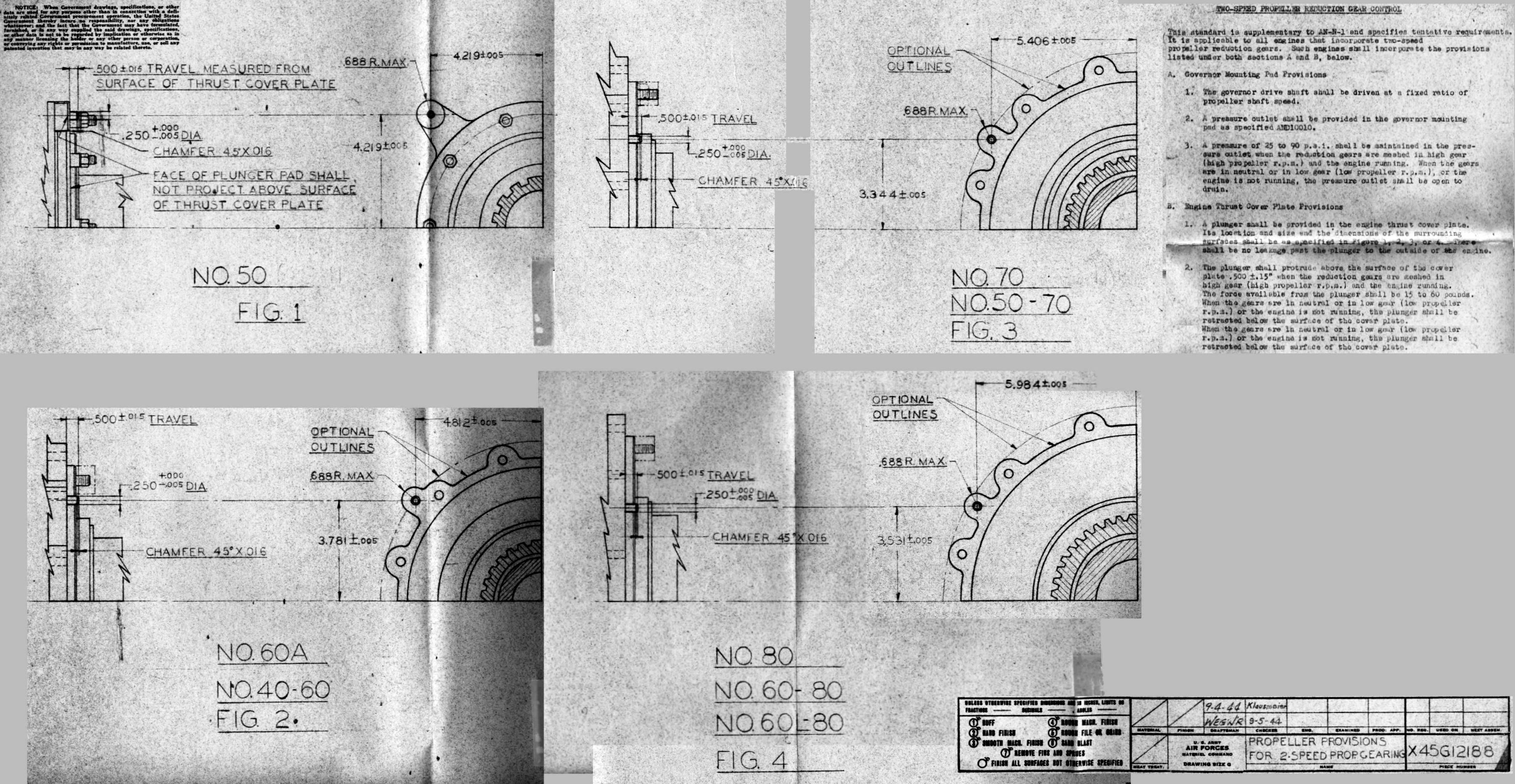
Propeller shaft sizes were also discussed. Each 4-blade propeller of the 20-ft dual-rotation combination would have a polar moment of inertial of 520 slug feet2, and for the #60-80 shaft size the #60 shaft would be stressed near the safe limit of 90,000 psi. The #70-80 shaft size did not only add appreciably to the shaft weight, but would also require a heavier nose section. Lycoming had been given data that would allow a decision between the above shafts. It was brought out that the #60L-80 shaft should be used if the #60-80 shaft size were chosen because the "L" size permitted the feathering of very wide blades. MatCmd strongly encouraged the use of #60L-80 shaft standard for the first dual-rotation test front end.
The single-rotation propeller Lycoming representatives mentioned were 22 ft in diameter and used #70 shaft, which would have a moment of inertia of about 1,200 slug feet2; a 26 ft propeller (Boeing) using a #70 shaft would have an 1,800 – 2,000 slug feet2. The 28 ft propeller MatCmd had studied had an estimated polar moment of inertia of 2,300 slug feet2. Using a #70 shaft with a 2.0" inside diameter, running at 450 propeller rpm gave a stress of 88,000 psi, which was just under the limit but left no allowance for higher propeller rpm or output. However, for engine test stand development work it was decided that a #70 shaft would be satisfactory.
For the large propellers discussed, two propeller manufacturers had established they would have self-contained control units, and another manufacturer had not yet formalized a design. In any case, it was not felt that the propeller requirements would be adequately handled by the transfer of engine oil for controlling these large propellers. Hence, MatCmd omitted the requirement propeller oil transfer rings, but the propeller governor pad was to be furnished as usual.
The two-speed shifting mechanism was discussed and MatCmd criticized the design because at one stage during the shifting sequence the engine and propeller were completely disengaged and a throttle adjustment was necessary to obtain the final reduction gear ratio changeover. MatCmd felt that the engine might be extremely sensitive to even slight throttle opening under such conditions, which might result in serious overspeed. Lycoming representatives felt the plan was practical but might involve further clutching action. A two-speed reduction gear similar to the one discussed was to be soon tested on a Lycoming XH-2470 engine; this test would provide further evidence of such a drive's practicality. [25 Apr 1944 Memorandum Report ENG-57-503-1190. Conference on Lycoming XR-7755 Engine, P281460]
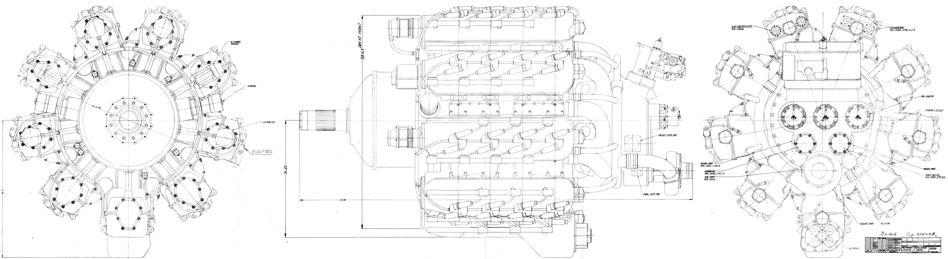 | |
| Lycoming X-7 Installation Drawing No. 80001, dated 4 Jan 1944 |
12 Apr 1944. Capt D.M. Ross, Capt C.J. Waters, and Messers Columbo, Prescott and Blackwood of MatCmd met with Sam K. Hoffman and J. Carpenter of Lycoming and E. Spaulding of Jack & Heintz at Wright Field to discuss several XR-7755 design items.
Lycoming expected the short-stroke single-cylinder engine would be ready for test by 18 Apr 1944 and the standard-stroke single-cylinder engine would be ready for test by 1 May 1944. The multi-cylinder crankshaft, connecting rods and pistons had been released for forging. Crankcase details were being finalized and forging drawings were expected soon.
Lycoming showed drawings with the spark plugs pocketed in cam housing cover recesses. Locating the plugs on the cylinder bank sides between the banks seemed inadvisable because of poor accessibility due to intake pipes, exhaust pipes and cam housing interference. Lycoming was measuring spark plug temperatures with the plugs submerged as described, and proposed to direct a cooling air blast into each plug recess using a lengthwise hollow on the cam box cover and an air outlet at the spark plug base for circulation. It was suggested that a cover over this lengthwise hollow would not only provide a cooling duct but would also provide space for ignition harness and possibly also function as electrical shielding. Capt Ross stated that the necessary openings might result in radio energy escaping; the shielding problem was a major one.
The Lycoming installation drawings indicated one Bendix Scintilla low-tension magneto and two distributors for each cylinder row pair. The original magneto turned 1 1/8 times engine speed. Capt Ross indicated that distributorless magnetos would run at 1/2 engine speed, but nine of these would be required, one for each cylinder bank; this could easily be provided later if required. Lycoming requested information on available ignition equipment so that the space required could be planned.
Lycoming estimated that 800 to 900 lb/in torque would be required at the crankshaft for starting at normal temperatures. This agreed with data provided by E. Spaulding of Jack & Heintz. Lycoming proposed using two direct-cranking starters to supply ample starting torque at 3:1 drive ratio. These starters would have their clutches set at 300 to 380 lb/in torque at the starter. During warm weather, one starter should be capable of starting the engine. The P&WA R-4360 had one such starter on a 3:1 drive, and Lycoming thought this adequate for the XR-7755. Lycoming preferred two starters rather than one large one so the starters could be mounted almost diametrically, thereby balancing gear loads, using smaller gears and being shorter. Lycoming said the weight of standard Jack & Heintz inertia direct cranking starter was about 45 lb, and with the inertial weight removed, weight would be about 38 lb. Jack & Heintz promised to send Lycoming drawings and weights for the 3:1 direct cranking and inertia-direct cranking starters so that Lycoming could investigate clearance for the various types. Lycoming stated that a 30 rpm starting speed would be sufficient. Use of three-tooth starter jaws in the inertia type and 12 tooth jaws on the direct cranking type in conjunction with a 6" diameter starter pad was agreeable to all parties.
Lycoming showed a method of flexible mounting that provided special mounting brackets spaced around a circular housing with the brackets fastened to an "I" shaped ring. MatCmd suggested that a tubular ring might save weight and be a construction method that was more familiar to airplane manufacturers.
In planning for a coolant outlet manifold, Lycoming noted that one was already available in the cored out portion of the mounting support housing. Some coolant heat may have been carried away by the intake air, but this would be a small fraction compared to oil heating. The idea was attractive by making the cooling system a more integral part of the engine, using parts already available without further weight addition.
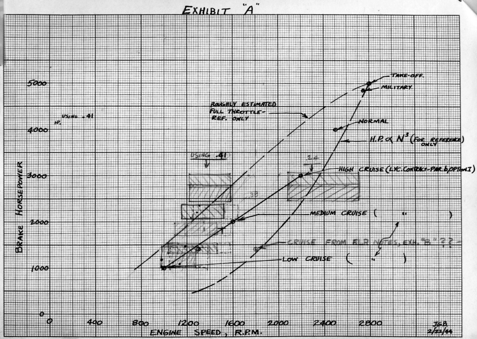
MatCmd had curves available on single- and dual-rotation propulsion efficiency versus propeller rpm. Sam Hoffman requested to analyze the data before further discussion on the subject of reduction gear ratios. MatCmd suggested that the gear ratio choices be made by matching the best-engine-economy cruise line against the best propulsive efficiency on a power versus engine speed graph. [3 May 1944 Memorandum Report ENG-57-503-1193. Conference on Lycoming XR-7755 Engine, P281432]
24, 25 Apr 1944. Ford Prescott visited Lycoming to discuss progress. Hoffman was having difficulty recruiting sufficient drafting and engineering help to complete the X-7 detail drawings. A previous arrangement with Engineering Services Company, Detroit, Michigan had worked well, producing numerous drawings in a short time based on Lycoming preliminary designs, but no Engineering Services personnel, or other personnel, were available. Hoffman thought six men working for four months were needed, and if they were unavailable, the schedule would slip by about six months. Letters to this effect were being prepared for the War Manpower Office in New York and Materiel Command at Wright Field through the AAF Resident Representative at Lycoming.
MatCmd had received a telephone call from the War Production Board (WPD) in Washington asking for a Lycoming representative familiar with machine tool requirements for the X-7; the WPD was hoping to establish a satisfactory delivery schedule. Certain machines Lycoming required were hard to obtain and needed in other production programs. Lycoming work to this point under the Letter Contract, which had been extended at intervals to accommodate these delays.
Hoffman stated that reduction gear ratios of 0.38 for low speed and 0.24 to 0.27 for high speed appeared feasible. Based on manufacturers' and MatCmd wishes, he thought the final ratios selected would be 0.38 and 0.26 . Prescott suggested a way to address the overhung pinions that carried the heavy low-speed loads by allowing the heavy load to be carried between two bearings and the lighter load on the overhung large pinion gear would be applied directly to the conical seat. Lycoming was preparing a revised layout. Parts then under test for the BX reduction gear were examined. The BX two-speed drive was similar to the proposed X-7 drive, except that none of the conical seats planned for X-7 pinion synchronization were eccentric. The BX reduction gear was to be thoroughly tested and Lycoming expected these tests to give valuable information for the X-7 design. Some discussion arose as to the power that was to be handled during gear change. Lycoming outlined a BX reduction gear motoring test series that it hoped would give data upon which an estimate of clutch size could be made for the proposed X-7 reduction gear.
Prescott examined X-7 single cylinders then being fabricated. All parts for the X-7 short-stroke test engine were to be completed in about a week, while the X-7 long-stroke test engine was to be completed in about 30 days. The X-7 cylinder head test program was to be in progress in the very near future.
Prescott examined the proposed X-7 intake manifolds and flame arrestors. After some discussion it was agreed that the most logical layout would use two long, narrow flame arrestors similar to those used in the Rolls-Royce Merlin. These two arrestors were to be incorporated into a manifold in which cylinders 1 and 2 were served by one and cylinders 3 and 4 by the other, a scheme that greatly reduced the pressure drop through the arrestors. The Rolls-Royce arrestor construction was extremely strong since all the arrestor segments passed directly from one side to the other and were not coiled up, as were some U.S. designs. The coiled construction depended on the brazing for mechanical strength while the Rolls-Royce type depended on the edgewise mechanical strength of the separate metal sheets that built up the arrestor structure.
Lycoming presented cam and accessory drive layouts, which were being revised. A compound gearing arrangement appeared attractive for driving the camshaft front ends. This arrangement, along with a straight-bevel drive, would be part of the revision. [4 May 1944 Memorandum Report ENG-57-503-1200. Lycoming "X-7" 5,000 hp Engine, P281669]
20-22 Jun 1944. Blackwood visited Lycoming and submitted a progress report. The X-7 short-stroke cylinder was scheduled for 150 hrs testing at 7.2:1 compression ratio – 50 hrs on the first set of parts, 65 hrs total. Check runs were to be made up to 265 imep and 53 inHgA boost (147 hp). The X-7 standard-stroke engine was to be in operation on 6 Jul 1944. It was temporarily running a cast-iron piston at 8.5:1 compression ratio. Lycoming planned a 15 hr run in, followed by tear down and inspection. The second engine was to be running by 1 Jul 1944. Accessory section drawings showed the gear loads had been centralized by a central web on the power takeoff and generator drive gears. Installation of two ball bearings instead of plain bearings was planned for the injector drive. Internal gear load on the injector drive was unbalanced. Wider impeller drive gears were being considered; two drives were being used. A crankshaft torsional test was being planned. [Penciled notes by J.G. Blackwood. RG 342 RD2311 XR-7755, 1943-1948: 503-602 Conf and Tel Notes.]
4 Aug 1944. Carpenter reported that Lycoming had encountered some 1-cylinder valve trouble but that the combination of nitrided valve stems and sodium/mercury-filled valve stems had eliminated the issue. Forgings were in for the pistons. Work on the reduction gear was proceeding, with 100 shifts having been accomplished. A crankshaft test rig was being laid out. The mechanical tachometer drive was to be omitted. [Penciled notes by J.G. Blackwood. RG 342 RD2311 XR-7755, 1943-1948: 503-602 Conf and Tel Notes.]14, 15 Aug 1944. Prescott visited Lycoming where a question arose as to the complete witnessing of tests covered by the contract. The AAF Resident Representative stated that due to a shortage of observers it was impossible to witness all tests during the MX-434 development program. The matter was referred to the Inspection Division, Engine Test Branch, Wright Field. In other programs with similar observer shortages, the observers decided which tests were most important and witnessed those. At intervals, they would look in on other tests in order to keep informed about their progress.
Dynamometers and controls had been on order for about a year, and their delay was interfering with single-cylinder development testing. Lycoming asked the Eastern Procurement District in New York City to expedite the delivery of a 300 hp dynamometer and all control equipment.
Prescott examined the cam drive and starter drive and found that his previous objections to the type of bevel gear mounting used in the starter drive had been addressed; the layouts were near completion.
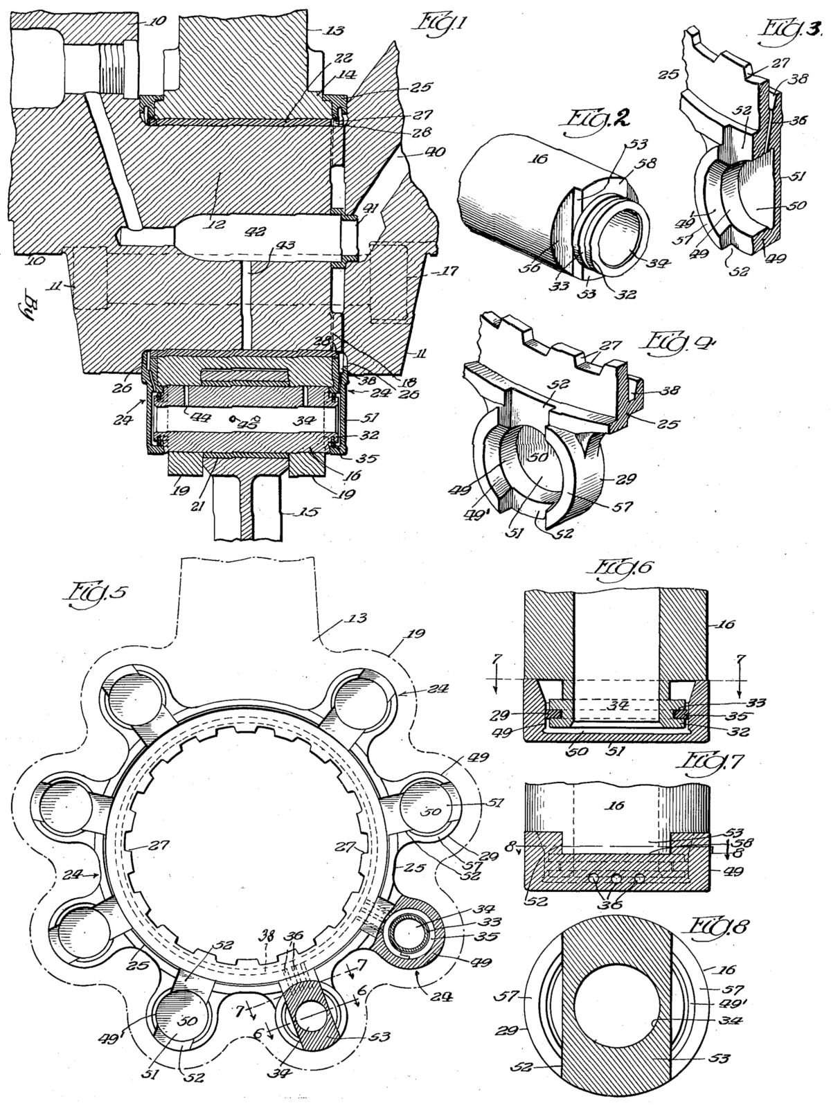
 |
| Patent for the Probable Two-Speed Dual Rotation Reduction Gear Design |
Prescott reviewed the proposed two-speed reduction gear. One ball bearing manufacturer proposed using a double bearing with a roller bearing for radial loads and a ball bearing for thrust loads. Prescott thought this arrangement was unnecessarily heavy. Another bearing manufacturer was satisfied with the mounting, loads and bearing life; it was decided to use this single-row ball bearing, which would save about 15 lb. MatCmd expected that a new type of hydro-controlled propeller was to be available for installation on the XR-7755. Consequently the first design incorporating a single-rotation propeller was to be made without using the hydro control oil holes and sealing rings necessary for use with the Hamilton-Standard Hydromatic propeller type then in use. Of course, such oil passages and seals were not necessary with electrically-controlled (Curtiss Electric) propellers. The new hydro propeller incorporated all operating mechanisms within the propeller assembly and did not require engine oil passages and seals.
The proposed two-speed reduction gear featured a special shift mechanism that made use of a balk ring, a device that permitted the gear to be disengaged from one speed ratio but prevented engaging the other ratio until synchronization had occurred; relative motion then ceased and the balk ring quickly engaged. A similar two-speed gear has evolved for the Lycoming H-2470 engine and this reduction gear was to be installed on a dynamometer setup with a flywheel replacing the propeller in order to test the gear shift mechanism. A shifting test program had completed 320 shifts without any failure or damage to the gears. Several shifts were demonstrated and the gears engaged with a surprisingly small amount of shock. The balk ring idea was originated by Lycoming engineers and permitted the gears to be engaged only when the proper relative internal gear speeds had been attained. Shifting occurred without shock loading in spite of the heavy flywheel. It was obvious that peculiar engine control problems might arise because of the unloaded engine operating during the shift interval. The complete test program included testing the two-speed gear by driving it with an automobile V-8 in order to determine the effect of engine acceleration when the engine was disconnected from the propeller. Final testing was planned for a complete engine/propeller and it was possible that some auxiliary throttle arrangement might have to be used to control engine speed within necessary limits.
Lycoming had designed a special test box for the two-speed clutch. A second test rig had been prepared to accomplish crankshaft fatigue tests by simulating bending and torque variations. Another test rig had been built to conduct supercharger inlet and scroll efficiency tests. Lycoming intended to perform as much testing as possible prior to testing on the actual engine.
Prescott examined the intake pipe and backfire screen layout in accordance with the previous visit. These were extremely simple, with a 1.5" x 10" backfire screen serving two adjacent cylinders, thereby keeping the backfire screen pressure drop and combustible mixture on the cylinder side as low as possible.
The latest cam box cover and low tension ignition featured small step-up transformers at each spark plug, which meant that the harness carried low voltage (around 100 V) and the insulation could be minimized. The proposed arrangement had been approved by spark plug and ignition coil manufacturers. The final design was to have a single high-tension connection between the coil and spark plug. This low-tension distribution system was expected to have superior altitude performance and radio noise prevention characteristics.
MatCmd had decided that the MX-434 engine would not have gun synchronizer impulse generators as it was doubtful that a gun would fire through the propeller on a large airplane and the two-speed reduction drive made gun synchronization exceedingly difficult. Mechanical tachometer drives were also to be eliminated in accordance with the proposed AN-9500c specification.
Lycoming had previously requested a small quantity of Grade 115/145 fuel covered by Specification AN-F-35 dated 13 Jun 1944 for use in single-cylinder testing. MatCmd did not expect any of the fuel to be available until January 1945.
Lycoming provided MatCmd two copies of the latest tentative XR-7755 specifications for information, review and comment. [21 Aug 1944 Memorandum Report ENG-57-503-1264. Conference on MX0434 Engine Design, P282134]
| Type | Weight | Shaft Size | Gear Ratio |
|---|---|---|---|
| Single-Speed, Single-Rotation | 390 | 70 | 0.244 |
| Single-Speed, Dual-Rotation | 690 | 60-80 | 0.244 |
| Two-Speed, Single-Rotation | 550 | 70 | 0.244 , 0.354 |
| Two-Speed, Dual-Rotation | 850 | 60-80 | 0.244 , 0.354 |
24 Aug 1944. Lycoming engineers Carpenter and Hoffman met with MatCmd civilian employees Ahern, Blackwood Buchtel, and Newman to further discuss reduction gear design. Lycoming presented reduction gear drawings, weight estimates, proposed propeller shaft sizes and proposed gear ratios.
MatCmd planned to study the designs, but opined that the choice for flight use would probably be the two-speed dual-rotation. Lycoming was to submit a formal study report and final layout in the near future.
Lycoming planned a simple test engine/reduction gear setup that would allow independent engine development and test. The test engine was to incorporate one gear train from the proposed two-speed gear set running at 0.56 ratio; this reduction gear would not be suitable for flight and the housing would not incorporate a propeller governor drive or pad. A No. 70 propeller shaft size was to be used. MatCmd was to provide an adjustable test club by March 1945 since it was estimated that a multi-cylinder engine might be available by then.
A single-cylinder engine with the same bore, stroke and compression ratio as the multi-cylinder engine exhibited an isfc of 0.328 lb/hp/hr at a 2,000 hp and 1,600 rpm equivalent multi-cylinder output. Lycoming estimated this would result in a 0.370 lb/hp/hr multi-cylinder bsfc. This testing also indicated a 265 psi imep at 2,600 rpm; 230 psi imep was required to obtain the 5,000 hp multi-cylinder takeoff rating.
The participants discussed a rough draft of Lycoming Specification No. 2020 dated 7 Aug 1944. They decided that that this specification should be written based on Specification AN-9501c, which was to be available in about one month. Lycoming furnished drawings covering the latest tentative accessory drive requirements to meet AN-9500c. [1 Sep 1944 Memorandum Report ENG-57-503-1278. Lycoming XR-7755 Engine, P282313]
31 Aug 1944. The Army Air Forces Materiel Command, after a rapid series of name changes, was absorbed by the new Air Technical Service Command (hereinafter ATSC).
 |
| Connecting Rod Patent |
13, 14 Sep 1944. Prescott visited Lycoming to review the latest XR-7755 design drawings. A number of drawings were in the process of being released for fabrication including various groups of drawings to make the parts required for one complete multi-cylinder engine. Additional parts required for three- and nine-cylinder engines were included in notes within the release. Other parts were also included for testing in test fixtures. Parts needed for then-current test programs were due on 15 Oct 1944 and parts for the multi-cylinder engine were due on 1 Feb 1945. Prescott, as usual, had (unspecified) suggestions for improving the parts. Among those parts released were the master and link rods, master rod oil seals, knuckle pins, crankpin bearings, cylinder head block, camshaft bearings, cam drive details and housing, pistons and rings. Lycoming planned to release drawings as rapidly as possible so that a full engine could be assembled during early spring 1945.
Lycoming engineers produced design drawings for single-speed single-rotation, two-speed single-rotation, single-speed dual-rotation and two-speed dual rotation, reduction gears. The single-speed single-rotation was expected to first be done with a 0.56 ratio and would provide Nos. 50 and 70 shaft ends in tandem to support two right-hand tractor propellers for torque stand operation. The ATSC wanted the two-speed dual-rotation option to be installed on the first complete engine. Lycoming still thought that the two-speed gear design that incorporated a balk ring was entirely successful in shift tests, having produced no failures in the extensive testing done thus far.
Prescott examined the fixture for testing the crankshaft serrated joint, which used the latest Gleason curvic-tooth type and incorporated four large cap screws at each crankpin joint. The cap screws were installed in the crankshaft using round-wire Aero-thread inserts to avoid stress concentration due to the sharp roots of conventional threads. The test fixture mounted either a dummy crankpin joint or an entire crankshaft section. The fixture included provisions for applying a bending load and a pre-stressed torque load after which torque reversals were supplied by means of a motor-driven eccentric that induced maximum load conditions.
Lycoming was planning a nose-to-nose test fixture to load and test the two-speed reduction drive. Tests were also to be run on the two-speed device simulating gear shifts with an actual engine and propeller. There was still no information available on the behavior of a large airplane engine, such as the XR-7755, when completely disconnected from the propeller as was to be the case in the short interval during propeller gear ratio shifts.
The rear accessory and supercharger coupling designs were nearing completion, but were presenting several troublesome details that were being worked; Lycoming expected that the entire rear section would be ready for detailing and release in the near future.
Prescott examined parts from the single-cylinder tests. A new design forged piston showed very satisfactory performance and strength. This piston incorporated a wide strut between pin bosses across the piston head. It also featured a large relief across the piston pin ends. Excessive piston pin deflection was noted during one test; Lycoming had designed a new pin with a heavier wall to eliminate this trouble. The piston ring setup was simple , conventional and exclusively good cast iron. There had been no breakage or scoring thus far. The double-scraper slotted oil ring was satisfactory at oil control. The intermediate rings had a 1.5° face taper and were positioned to scrape down. The top ring was a 15° wedge with a chrome-plated taperless face. Prescott observed that the top rings were in excellent condition and declared the ring setup satisfactory.
The nitrided-stem valves appeared to have completely overcome valve guide wear. Lycoming had also procured exhaust valves with sodium-mercury-filled stems instead of the previous solid sodium ones. This had been recommended by the valve manufacturer based on its experience with other engined, which were probably air-cooled. In the liquid-cooled engine with a 250° coolant temperature, Lycoming feared that much of the sodium would remain solid. However, the wear properties of these valves with their nitrided stems appeared to be entirely satisfactory. [23 Sep 1944 Memorandum Report TSELA-3B-503-1295. R-7755 Engine – 5,000 hp, P282219]
8, 9 Nov 1944. Prescott visited Lycoming to discuss development progress and drawings released for fabrication of multi-cylinder and test engines. He discussed details of proposed piston and connecting rod stress coat tests, along with methods of discussing master and link rod fatigue conditions.
Prescott thought Lycoming Report No. X678 had been vague about the design of the dual-rotation propeller shafts and asked whether the calculations had been based on the 60L-80 or the 60-80 standards, the difference being the inner shaft, which was about 5" longer to accommodate wide dual-rotation blades. Lycoming stated that the 60L-80 standard had been used although the drawings showed 60-80 shaft ends. Lycoming engineers could see no reason for the 60L-80 design with its increased weight and crankcase clearance it required. They reasoned that the liquid-cooled XR-7755 would have a spinner three feet or more in diameter, and planned to send a sketch to Wright Field showing possible weight and space savings in hopes of a final decision in the near future.
The question of furnishing AND-100002 Type I and Type III accessory drives was discussed. Lycoming stated that a Type I and Type II could be furnished without extensive redesign, but the Type III would call for basic gear train changes. (The type III drive was intended to drive cabin superchargers, which could require over 200 hp) Wright Field maintained there was a real need for Type III drives in certain bomber installations to deliver the full power of the Type III specification. Lycoming was to study the matter and advise the PPL regarding the steps necessary to redesign to supply both Type I and Type III drives.
Wright Field wanted copies of the latest installation drawings so that isometric drawings could be made for presentation of the project in Washington, D.C. Sam Hoffman said that preparation of such a drawing by Lycoming would require hiring an isometric artist and could not be done without an authorization for employment. Subsequent discussion resulted in Wright Field relaxing its isometric drawing requirements and settling for a new installation drawing, which Lycoming could produce in 30 to 60 days.
The parts had been ordered with a 1 Feb 1945 delivery date; assembly of a complete XR-7755 was expected in late spring 1945. [24 Nov 1944 Memorandum Report TSEPL-5-503-3038. Lycoming R-7755 Engine, P282728]
4, 5 Dec 1944. Prescott traveled to Lycoming to discuss XR-7755 design details and to help with final drawing checks before they were released to the shop. During study of the engine mount ring a very simple design evolved whereby two small forgings were used to attach the engine to the mount ring, yielding a mount suitable for both test stand running and aircraft installation. The forgings connected the engine mounting ears, through vibration isolators, to the mount ring, which was made from 4" OD, 0.25" wall steel tube rolled into a ring about 48" in diameter. Lycoming requested information on sources for such a ring, and Prescott suggested American Tube Bending Company of New Haven, Connecticut; Combustion Engineering Corporation of Chattanooga, Tennessee; and the Crane Company Pittsburg, Pennsylvania (the plant that was closest to Williamsport).
The reduction gear design was again reviewed, this time in conjunction with the latest torquemeter design, shift control, and the high-pressure oil pumps associated with these items. The reduction gear design was in its final steps and drawings were being made by the Engineering Services Corporation; these were to be reviewed during the next ATSC Representative visit. The two-speed dual-rotation gear unit was estimated to weigh 907 lb. Of this, 14 lb could be saved by using magnesium instead of aluminum alloy for the nose casting, which was lightly loaded. No pattern change would be required, which meant that the first casting would probably be magnesium. A second reduction gear design incorporating a single No. 70 shaft, single reduction ratio, torquemeter and appropriate reduction ratio would be suitable for engine operation on the dynamometer. As far as possible the parts used in this reduction gear were identical to those in the two-speed reduction gear required for aircraft.
Prescott examined design drawings incorporating a Wright Aeronautical Corporation Chilton dynamic vibration absorber to the Lycoming front and rear crank cheeks. Prescott had read in the Nov 1944 S.A.E. Journal that a lead coating prevented galling of the damper pins. Lycoming planned to investigate incorporation of an anti-galling treatment for the damper rubbing parts.
A number of sectional assembly drawings through engine mechanisms showing drives and other internal engine parts were examined. Lycoming agreed to forward copies of these drawings to the ATSC.
The latest weight estimates put the single-speed single-rotation engine with torquemeter at 5,573 lb and the two-speed dual-rotation engine with torquemeter at 6,033 lb.
Prescott examined many crankcase details in preparation for drawing release. He suggested that the long through studs, which ran from front to rear of the steel crankcase, be provided with additional mating lands to reduce the 9" unsupported length. These lengths were also identical from one section to the next, which might introduce sympathetic resonances in the studs, possibly causing fatigue and breakage. Studs with different unsupported lengths were preferred. Lycoming agreed to incorporate these suggestions into future layouts. Crankcase fabrication was planned to begin in the near future.
Methods of locking the crankpin Gleason joint retaining bolts were discussed and a simple positive locking scheme evolved; this would be detailed and incorporated prior to release of the crankshaft assembly drawing. Crankshaft forgings were already in the shop and fabrication was expected to begin in the near future.
Piston ring drawings showed cast iron rings of the type then running in single-cylinder engines. Only the top ring was chrome plated on its outside diameter. Single-cylinder testing had indicated the ring pack was satisfactory and its design would be used in the multi-cylinder engine.
The intake manifold drawing revealed previously-discussed features including a connector sleeve with buttress-type shrink bands adapted to retain the connector sleeve in the supercharger housing. While this scheme was not expected to be troublesome, if it were a sleeve could be threaded and provided with a thin flange locked by means of a small pin through the flange and into the supercharger outlet boss face; this was strictly a backup plan.
The camshaft quill drive served as an oil gallery to the valve gear. Prescott objected that the oil pressure would tend to force the bevel gears off the quill shaft ends, thereby pushing them into their mating gears. He doubted that the bevel gear end thrust would exceed the oil pressure thrust under all conditions. Several schemes to address this issue were discussed and Lycoming agreed to adopt one to eliminate the condition prior to drawing release.
Two single-cylinder crankcases had cracked in the curved side about 3" away from the cylinder attachment boss. While the crankcases had been repaired and continued in service, the failure root cause was explored. The cracks appeared at the point where the diaphragms carrying the main bearing saddles joined the case walls, which led to the conclusion that welding under the cylinder flange boss must have failed causing the entire gas load to be carried by the crankcase curved skin. Repair methods were discussed and Lycoming would repair the cases. This highlighted the utility of a welded steel test crankcase in that a cast case would have required replacement.
Prescott observed the camshaft shifting test setup in action. Approximately 500 shifts had been made with no effect on the valve operating parts. This test rig did not simulate gas loads on the exhaust valves, which meant it was less severe than the actual engine; to compensate it was operated at higher speed. A new cam was being designed to eliminate the deep relief grooves between the high-power and cruising cams. These cams were to be ground to provide a 45° chamfer that would allow roller rockers to pass from one cam to the other. The camshaft manufacturer was involved in the design to ensure the design could actually be ground.
One single-cylinder test stand was equipped with a modified Farnboro pressure indicator. Data was being collected to determine the effects of various compression ratios, spark advances, speeds, etc., on the maximum pressure magnitude and timing.
Hoffman suggested another ATSC Representative visit to release additional drawings on 28-29 Dec 1944. He wanted to get as many drawings as possible released during 1944. Prescott questioned whether the February 1945 delivery date for most parts was still possible. Hoffman stated that some of the parts might be delayed by as much as 90 days beyond the desired February date, but that he still expected fabrication of a complete engine in late spring 1945. [8 Dec 1944 Memorandum Report TSEPL-5-503-3046. Conference on Lycoming XR-7755 Engine, P280004]
Send mail to
![]() with questions or comments about this web site.
with questions or comments about this web site.
![]()