(dated 8 Jan 1942)
The Lycoming XR-7755
Working Topic 1943
by Kimble D. McCutcheon
|
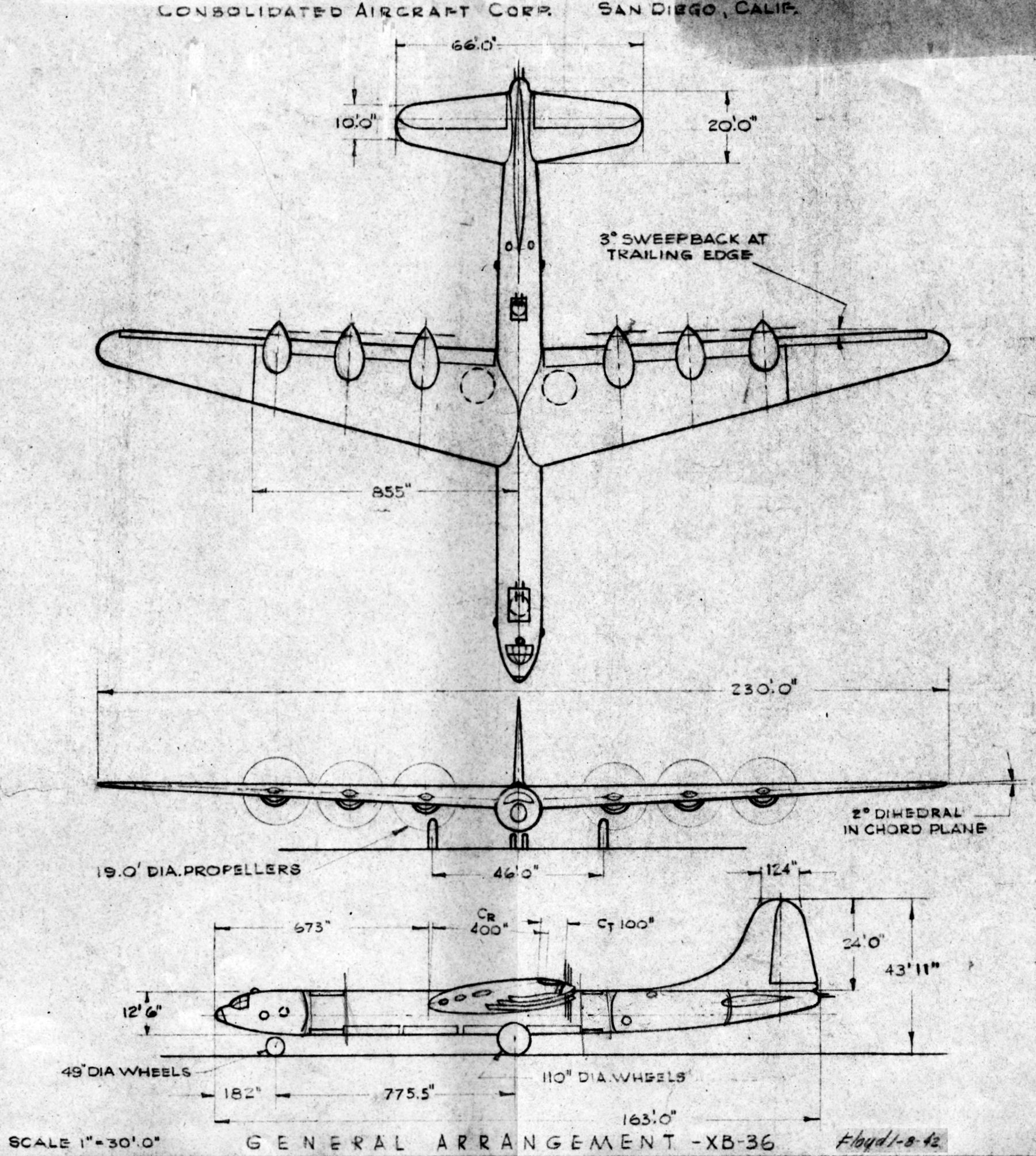
| XB-36 (dated 8 Jan 1942) |
BX Engine Installation in the CVAC XB-36
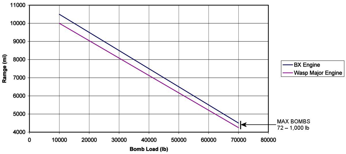
Sometime in late 1942 the Army Air Corps asked CVAC to compare the Lycoming BX to the P&WA Wasp Major, which had been selected to power its XB-36 bomber. On 8 Feb 1943, CVAC released its report, "Study – Lycoming BX Engine", which included drawings, an installation narrative, and performance and weight comparisons.
 |
 |
 |
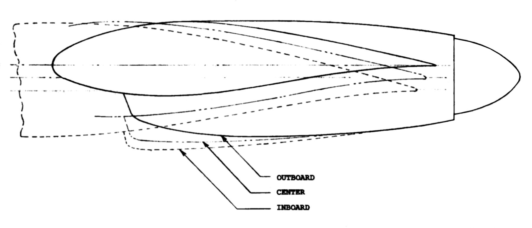 |
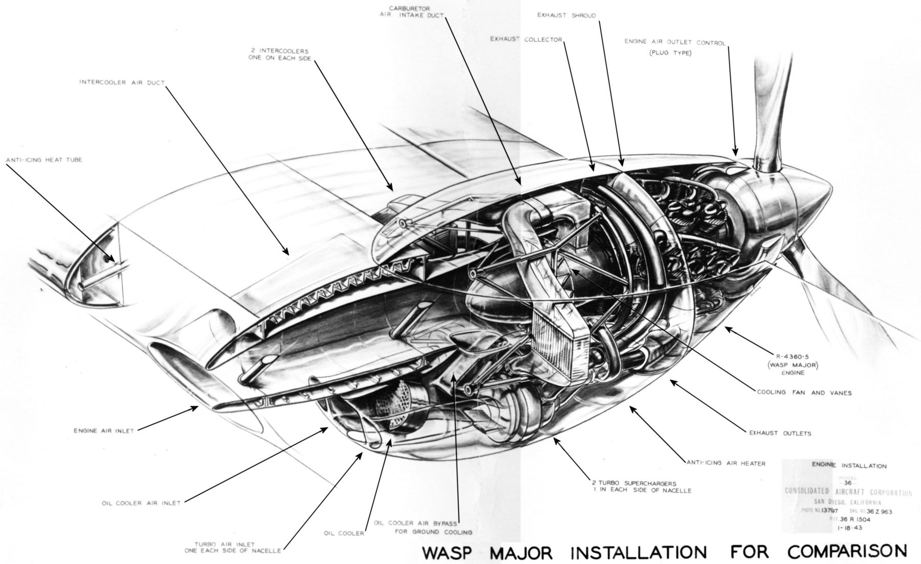
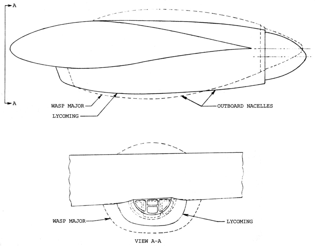
| Lycoming BX Engine Installation | P&WA Wasp Major Engine Installation | BX and Wasp Major Nacelle Outlines | BX Inboard, Center and Outboard Nacelle Outlines |
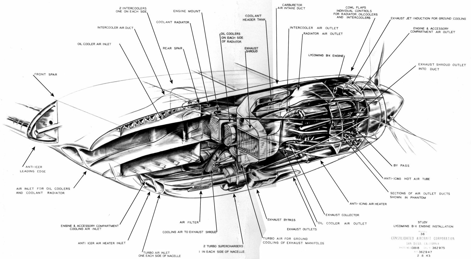
Installation
The engine, attached to the rear spar, drove a pusher propeller located aft of the wing trailing edge. Two General Electric type BM turbosuperchargers per engine were located side-by-side in the lower portion of the nacelle. Cooling air to the coolant radiator, oil coolers and intercoolers was supplied from leading edge ducts and exhausted through an annular opening around the propeller spinner. Flaps controlled the cooling air flow control for each cooling unit by varying its exit area. A main air duct leading from the wing leading edge divided into three just ahead of the rear spar; the center duct supplied the coolant radiator and the outer ducts supplied the oil coolers on either side of the coolant radiator. The two intercoolers, located outboard of the oil coolers, had separate leading edge entrances on either side of the main duct entrance.
Ground cooling was achieved via augmenters into which a portion of the exhaust from the aft three cylinders of the upper two cylinder banks was discharged into the radiator and oil cooler ducts near the duct exits. These exhaust jets entrained cooling air, augmenting its flow through the cooling system. Exhaust for the augmenters came from an auxiliary exhaust manifold connected by a valve to the upper-cylinder exhaust manifolds. This auxiliary manifold was only used for ground operations as the valve retracted flush against with the main manifold and closed the auxiliary outlet during normal operation. Cooling for the engine exhaust shrouds was provided by air led from the engine air inlet ahead of the turbocharger and discharged into the intercooler ducts aft of the intercoolers near their exhaust duct exits. For ground operation, air from one of the two turbochargers was bypassed to the exhaust shrouds. Backflow to the normal inlet was prevented by a valve, which for normal operation closed the bypass duct. The engine compartment was ventilated directly from a duct located between the two turbocharger air intake ducts. This air dumped into the engine compartment and exhausted through ports in the radiator and oil cooler ducts just aft of the augmenter jets. Ventilation for ground operation was provided by jets in the radiator and oil cooler ducts.
Dual General Electric type BM turbochargers provide greater economy for cruising operation. At high altitudes and low powers where the turbocharger efficiency begins to drop, provision is made for bypassing one turbocharger, thereby doubling the exhaust gas flow through the other turbocharger and maintaining good turbocharger efficiency.
| Metric | Condition 1 BX Lower SFC Increases Range |
Condition 2 BX Lower SFC Increases Bomb Load for 10,000 Mile Range |
Condition 3 BX Lower SFC Reduces Fuel and Gross Weight Required for 10,000 Mile Range with 10,000 lb Bombs |
|||
|---|---|---|---|---|---|---|
| BX | Wasp Major | BX | Wasp Major | BX | Wasp Major | |
| Gross Weight (lb) | 265,000 | 265,000 | 265,000 | 265,000 | 251,500 | 265,000 |
| Maximum Range (mi) | 10,750 | 10,000 | 10,000 | 10,000 | 10,000 | 10,000 |
| Bomb Load (Dropped 1/2 Range) | 20–500 lb | 20–500 lb | 35–500 lb | 20–500 lb | 20–500 lb | 20–500 lb |
| High Speed at 30,000 ft (mph) | 366* | 369 | 366* | 369 | 369 | 369 |
| Service Ceiling at 0.3 Range (ft) | 40,800 | 40,000 | 40,500 | 40,000 | 41,300 | 40,000 |
| Takeoff Over 50 ft Obstacle (ft) | 4,750 | 5,000 | 4,750 | ,5000 | 4,350 | 5,000 |
| * The lower BX engine installation drag is estimated to increase top speed by 2 mph; however, using the available gear ratios and favoring cruising gives a propeller tip speed loss that reduces the top speed by 5 mph, thereby giving 366 mph for the BX engine installation. | ||||||
 |
| (Optimum Altitude Cruise with Bombs Dropped at Half Range) |
| Item | Lycoming BX | P&WA Wasp Major |
|---|---|---|
| Engines (6 with two-speed reduction gear, including 15 lb/eng for residual oil) | 19,890 | 20,636 |
| Nacelles | ||
| Engine Mounts (6) | 1,820 | 1,520 |
| Flexible Mounts | 420 | 804 |
| Cowling | 1,550 | 1.786 |
| Miscellaneous | 86 | 86 |
| Total | (3,876) | (4,196) |
| Engine Accessories | ||
| Turbochargers (12) | 3,000 | 3,000 |
| Turbocharger Supports | 89 | 89 |
| Intercoolers (12) | 851 | 851 |
| Intercooler Supports | 48 | 48 |
| Oil Coolers (12) | 800 | 642 |
| Oil Cooler Supports | 35 | 30 |
| Exhaust System (excluding heat exchangers) | 1,750 | 1,575 |
| Air Ducts | 1,170 | 932 |
| Fuel Pumps (6) | 24 | 24 |
| Miscellaneous | 76 | 76 |
| Total | (7,843) | (7,267) |
| Power Plant Controls | ||
| Turbocharger Controls | 20 | 20 |
| Turbocharger Regulators | 45 | 45 |
| Regulator Supports | 15 | 15 |
| Throttle and Mixture | 149 | 149 |
| Cooling Air Exit Flaps | 250 | 119 |
| Power Plant Controls in Fuselage | 120 | 120 |
| Propeller | 150 | 150 |
| Miscellaneous | 84 | 84 |
| Total | (833) | (702) |
| Propellers (6) | ||
| Total | (6,210) | (6,210) |
| Systems | ||
| Starting | ||
| Gear Boxes and Shafts | 150 | 150 |
| Portable Starter and Shaft | 50 | 50 |
| Oil | 261 | 261 |
| Fuel (excludes protection) | 737 | 737 |
| Power Plant Instruments | 113 | 113 |
| Cooling | ||
| Fans | – | 1,602 |
| Coolant (70% ethylene glycol, 30 gal/eng at 9 lb/gal) | 1,620 | – |
| Coolant Radiators (6) | 1,650 | – |
| Piping, Expansion Tank, Radiator Supports | 450 | – |
| Total | (4,290) | (1,602) |
| Total Power Plant | 44,253 | 41,964 |
|
Notes: 1) Other items in weight empty are estimated to be the same for both engine types 2) Increase in weight empty with BX engine = 2,289 lb. 3) Decrease in fuel to maintain constant gross weight (oil is 4% fuel by volume) = 2,289 / 6.3 = 363 gal | ||
1 Jun 1943. Materiel Command (hereinafter MatCmd) civilian employees J. Glen Blackwood and Opie Chenoweth briefed Lycoming representatives W.K. Cooper, Samuel K. Hoffman, P.G. Garlent and E.A. Johnson on an engine development program in which Lycoming might participate. It was a long-range bomber engine with a 5,000 hp takeoff rating, very low cruise specific fuel consumption at 25 to 80% normal power, two-speed dual-rotation reduction gear, fuel injection, 36" height if practical and Grade 130 fuel usage. No constraints were placed on design, cylinder arrangement, number or size. No altitude rating was required although an exhaust turbosupercharger could be used to provide sea-level power at altitude or achieve takeoff power. MatCmd suggested that Lycoming's program might include calibration and 50-hr endurance tests of several different-sized cylinders, twin-cylinder endurance test, design studies and calculations for the full-up engine, durability tests on the two-speed reduction gear, fuel injection, coolant pump, ignition system, accessory section, oil pump and similar items, an option of furnishing a few engines. Additional items could then cover 50-hr and 150-hr tests. Chenoweth expressed a preference for a fixed-price contract. MatCmd and Lycoming at that time referred to this proposed engine as X-5. This was essentially a twinned XH-2470 with 48 cylinders.[8 Jun 1943 Memorandum Report ENG-57-503-888. Conference between Lycoming and Materiel Command Representatives on a Proposed Engine Development. RG342 RD3024 Engines - Lycoming - General 1933-45 (XR-7755)]
MatCmd suggested that this engine might weigh more than an engine using fewer crankshafts. Hoffmen said that studies made of radial designs revealed that the master rod, crankpins and knuckle pins become so large that there is no weight savings. While MatCmd considered the X-6 engine arrangement satisfactory, Chenoweth opined that the relatively small displacement might result in sacrificing sfc or power. Chenoweth suggested to err on the side of too much displacement in order to safeguard future development and limit bmep to 190 psi.
| Cylinder Bore x Stroke (inches) | Displacement (in³) | bmep at 2,900 rpm (psi) |
|---|---|---|
| 6.125 x 6.250 | 6,629.56 | 206 |
| 6.375 x 6.375 | 7,325.42 | 186 |
| 6.500 x 6.500 | 7,664.84 | 176 |
Hoffman agreed to study the 6.500" x 6.500" cylinder size as a means to reduce bmep and increase sfc. MatCmd suggested eliminating the gear-driven supercharger since it reduced sfc due to the power required to drive it; the turbochargers could be used instead. Hoffman was reluctant to pursue such a radical design. [Penciled notes by J.G. Blackwood. RG 342 RD2311 XR-7755, 1943-1948: 503-602 Conf and Tel Notes.]
28 Aug 1943. Letter Contract W 33-038 ac-564 (11169) for single-cylinder experimental engines applicable to Lycoming X-6 development was signed.
Send mail to
![]() with questions or comments about this web site.
with questions or comments about this web site.
![]()