
Fig. 1. British supercharger drive, circa 1920. Engine oil provided lubrication on this example. German designs often used a separate reservoir and dedicated oil pump.
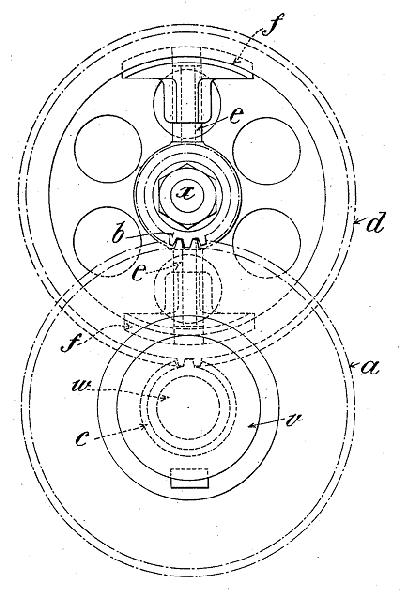
Fig. 2. Centrifugal clutch patented by Heron and Green.
Supercharger Development in the U.S. During the Inter-War Period
by Paul Dempsey
This paper describes some major developments in aircraft superchargers that took place in the United States between 1918 and the Second World War. Emphasis is on the supercharger itself. Other developments that contributed to the success of the technology—doped fuels, reduction gears, variable-pitch propellers—will have to wait for another time.
Rationale
Engines induct air by volume, but consume oxygen by weight. As the atmosphere thins at high altitudes, fewer oxygen molecules are available for combustion. A naturally-aspirated engine loses about half of its rated power at 20,000 ft. Forced induction is a merely a way to increase the density of the charge.
Normalized Boost
Initially researchers viewed superchargers solely as a means of altitude compensation. The aim was to restore lost power by maintaining, but never exceeding, sea-level manifold pressure as the airplane climbed. As Dr. Stanford Moss put it, a normalized supercharger “kidded the engine into thinking it was a sea level.”[1] Brake mean effective pressure (BMEP), exhaust temperature and the heat lost to the cooling system remained within design limits.
The ability to operate with impunity at high altitudes resulted in increased speed and slightly more than anticipated engine power. The rarified atmosphere reduced drag on the airplane and backpressure on the exhaust. The loss of lift could be compensated for by greater angles of attack.
Ground Boost
The alternative was to take the bull by the horns and apply boost continuously from take-off to maximum altitude. Ground boost required high-octane fuel and a close integration of the supercharger and the engine during the design stage, which as described below, was often lacking.
Adiabatic Efficiency
Adiabatic (or isothermal) efficiency was and remains the most frequently used measure of supercharger performance. Compressing air generates heat as a bicycle pump or diesel ignition demonstrates. In an ideal thermodynamic world—a world without entropy—an air compressor would neither gain nor lose heat to external sources. Such an adiabatic compressor would impart no more heat to the air than generated by the work of compression:
T2 = T1 x (P2 / P1)0.140, where
T1 = absolute inlet temperature in °Rankine (°R = 460 + °F)
T2 = absolute discharge temperature in °R
P1 = inlet pressure,
P2 = discharge pressure,
0.140 = the exponent generally used for air
Real-world compressors put significantly more heat into the charge—heat that increases pressure and reduces density. Adiabatic efficiency is the measure of how closely the compressor approaches the ideal:
Adiabatic Efficiency = (T2 – T1) actual / (T2 – T1) ideal
The National Advisory Committee for Aeronautics (NACA, predecessor to NASA) did not establish a standard for these calculations until 1941. Before that time, researchers were free to follow their instincts, which led to exaggerated claims. Some vintage superchargers were assigned adiabatic efficiencies of 80%. Now, a century later, only a handful of superchargers achieve efficiencies of 75% and when they do, it is over a very narrow operating range. The current SAE J-1723 standard was adopted in 1995. The standard calls for an inlet temperature of 537°R and an ambient pressure 29.23 inHgAbs. To more accurately measure compressor work, efficiency calculations must also take the energy content of inlet-air velocity into account.
Other measures of supercharger performance include volumetric efficiency (rpm-dependent for centrifugal compressors and hovering near 100% for positive-displacement Roots blowers), mechanical efficiency and power consumption. The latter is another tricky concept that awaited the arrival of digital computers to achieve a degree of precision.
Key Concepts
As with other human constructs, forced induction is a kind of narrative based on a few relatively simple ideas. Several of the more important are:
Boost – pressure above atmospheric in the manifold. Because density diminishes and pressure increases with heat, a really inefficient supercharger can heat the charge enough to generate boost while adding little or nothing to engine power output.
Mass flow rate – air density multiplied by the volumetric flow rate describes the output of the supercharger. Early researchers, with no convenient method of determining manifold charge density, came at the problem indirectly by measuring the volumetric flow rate (ft³/min) and correcting for temperature at the carburetor inlet.
Pressure ratio (pr) – compressor discharge pressure divided by inlet pressure.
Surge or stall – occurs when the compressor can no longer overcome system resistance. As stall approaches, manifold pressure rises. The compressor responds by pumping less air at a higher pressure. Closing down the nozzle on a water hose has a similar effect—less water flows through the nozzle, but at a higher pressure. At some point, the compressor can do no more and the air flow reverses. Impeller vanes stall much like an airfoil when forward velocity is lost. With no input from the compressor, manifold pressure falls. Impeller vanes then recover from the stall and resume their pumping function. Manifold pressure builds to the level that precipitates another stall. The cycle continues, often accompanied by loud “barking,” broken impeller blades, and bearing failure. Unless provision is made to relieve the pressure, turbochargers surge as they spool down under closed throttle. Surge also occurs when an overly large supercharger, one that delivers more air than the engine can ingest, is fitted.
Choke or stonewall – occurs when a centrifugal impeller spins fast enough to generate sonic air velocity at the inlet nozzle or diffuser throat. With little resistance to flow, the volume of air delivered increases and the pressure drops. The resulting shock waves choke off air delivery. An undersized (and under-loaded) turbocharger can attain choke speeds.
Choke (low pressure and high volume) and surge (high pressure and low volume) define the flow boundaries of compressor operation. Impeller rpm is the mechanical limit.
Power absorption – another dubious number. The intake manifold cannot be viewed simply as an open-ended container that fills faster than its empties. Until recently, engineers had no way of calculating the effects of friction, turbulence, flow separation and reflected pressure waves on power requirements.
Types
After the First World War supercharger development concentrated on gear-driven centrifugal compressors and turbochargers. NACA was almost alone in the pursuit of the Roots blower.
|
Fig. 1. British supercharger drive, circa 1920. Engine oil provided lubrication on this example. German designs often used a separate reservoir and dedicated oil pump. |
|
Fig. 2. Centrifugal clutch patented by Heron and Green. |
Gear-Driven Centrifugal Blowers
A centrifugal compressor consists of an impeller and a diffuser housed in a helical casing, or scroll. The diffuser, sometimes called the stator, occupies the annular space between the impeller and scroll. Passages created by the diffuser vanes open wider as they approach the discharge throat. Vanes on the impeller wheel are arranged radially and may be straight or curved. The use of curved vanes came relatively late in the period and improved efficiency.
Air enters at the impeller hub, rotates with the impeller and, under the influence of centrifugal force, moves outward in a path defined by the impeller vanes. Upon contact with the diffuser, the air expands and slows, converting much of its kinetic energy into static pressure.
Because the impeller cannot be allowed to make physical contact with the shroud, there is always some leakage between the vane tips and the scroll. The seal consists of air, an elastic medium. At low rotational speeds the impeller merely flays about delivering little or no output. As tip velocity increases, the air seal becomes more positive and the compressor begins to pump. Unlike Roots blowers that move the same volume of air per revolution, centrifugal compressors are dynamic machines, whose output increases as the square of speed—double the speed and the output theoretically quadruples.
Inertia
Work on aircraft superchargers began in Europe around 1915 with the intent of normalizing output at high altitudes. Initially experiments were carried out with a variety of pumps, but within a year or so the French settled on the Rateau turbocharger. The Royal Aircraft Factory concentrated on gear-driven centrifugal pumps until about 1917, then turned to turbochargers and, in the years immediately after the war, resumed work on geared compressors. J.E. Ellor, who would become the leading British authority on supercharging, directed these efforts. German researchers concentrated on direct-drive superchargers until the Treaty of Versailles put a temporary halt on aircraft research. When research efforts resumed in the 1930s, the focus was on geared centrifugal compressors. Only one German airplane of WW2 was turbocharged.
In order provide even moderate levels of boost, centrifugal impellers had to be geared up to turn at five or six times crankshaft speed (Fig. 1). At these speeds, the inertia of the impeller and its drive gears was about equal to that of the propeller. When coupled to a torsionally flexible crankshaft, immense stresses were put on the drive train. Gear teeth stripped during acceleration (most pronounced when the engine started) and deceleration.
In 1916, Sam D. Heron observed the flight test of a supercharged BE2. As Heron later put it for publication, “The observer sat forward with his feet under the fuel tank and over the supercharger’s gear drive. The gears were quite inadequate and the pinion failed in flight, producing showers of sparks and a feeling of distinct concern.”[2] Since Heron was not the most equitable of men and his immediate reaction was probably less restrained.
The Royal Aircraft Factory tried various expedients to reduce or at least dampen forces acting on the gears. Experiments were made with lightweight, sheet-steel rotors and various sorts of cushion drives. One of these drive mechanisms, a centrifugal slip clutch designed by Heron and F.M Green, appears to have solved the problem (Fig. 2). The clutch was used on the Armstrong-Siddeley Jaguar of 1926, the first supercharged radial engine to achieve operational status. About the same time, a modified version of the clutch appeared on the Bristol Jupiter.
Developments in the U.S.
Dr. Sanford A. Moss (1872 – 1946) made the turbocharger practical, advanced the cause of gas turbines, and ended his long career by pressurizing civilian airliners. Earning a doctorate from Cornell in 1903, he was immediately hired by General Electric to head up their turbine research facility at West Lynn, Massachusetts, where he would remain until retirement in 1938. Some idea of his thinking comes about from his habit of asking prospective employees if, as a child, they had ever taken a clock apart to see how it works. For “A young fellow who never took a clock apart can never become a mechanical engineer.”
According to Dr. Moss, around 1900 the French engineer Auguste Rateau (1862-1930) was the first to compress air with a centrifugal pump. Prior to that time centrifugal pumps were limited to moving water and other incompressible fluids. Rateau made the discharge nozzle convergent so that the air stream accelerated upon discharge and would subsequently gain pressure through expansion.
As part of its work on gas turbines, General Electric made the same discovery in 1904 and almost immediately began manufacture centrifugal air and gas compressors. GE may have been the first to incorporate a vaned diffuser to assist in expansion. The first compressor was installed at the Lynn Works in 1906 and remained in service until at least 1940. GE went on to build a variety of single and multi-stage compressors with tip velocities of from 500 to 1,500 feet per second (fps) and rotational speeds of 3,600 to 20,000 rpm. Moss would apply what was learned at Lynn to superchargers.
The first geared centrifugal blower for aircraft built in the United States was intended for use on inline engines. In an attempt to mitigate the effects of torsional vibration, the blower took power off the crankshaft through a small-diameter flexible shaft. Ground tests on a Liberty engine were conducted between 1918 and 1920.
Moss, as representative of the leading U.S. manufacturer of centrifugal pumps, may have been personally involved in this project. While his work on turbochargers would earn him a Collier Trophy, Moss had a deep affection for gear-driven superchargers. In a 1941 Popular Science profile, the scientist was described “as a disappointed man.”[3] Too much publicity had been given to his work on turbos. The writer continues, obviously paraphrasing Moss: His more important contribution had been in the area of gear-driven superchargers “of value in improving power on the take-off, as well as its main purpose of maintaining power at altitude…” While the turbocharger gives better performance at high altitude, “few people wanted to fly above 20,000 ft…[which] was both uncomfortable and dangerous for the aviator. Use of the turbo-supercharger has been limited to a few experimental ships and the most advanced Army planes. And though the Air Corps engineers worked eagerly with Dr. Moss to develop the turbo-supercharger, it never seems to him that the tactical units made adequate use of its possibilities.”
All this was changing as the interview was published. Moss collaborated with the Duesenberg brothers on the first geared supercharger used on an American racing car. This machine won the Indianapolis race in 1924. The compressor mounted near the center of the straight-eight engine and took power through a shaft from the accessory drive section at the front of the block. The shaft acted as a torsion bar to cushion the drive gears. Harry Miller also took advantage of Dr. Moss’s services and had him design a two-stage centrifugal compressor for his 91 CID front-wheel-drive cars (Fig. 3).
 |
Fig. 3. Miller supercharger designed by Dr. Moss. An unusual feature is the small impeller installed in the intake nozzle. (Courtesy Miller/Offenhauser Society) |
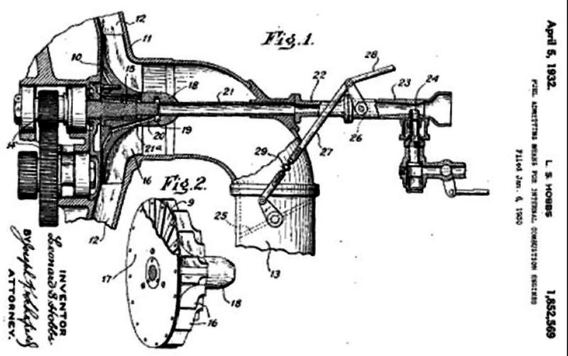 |
Fig. 4. Early Pratt & Whitney centrifugal blower with air throttling to regulate boost. The curved-vane, semi-closed, impeller represented an advance over the star-shaped impellers used earlier. |
Pratt & Whitney Wasp
General Electric supplied impellers and stators for Pratt & Whitney engines, which drove through spring-loaded slip couplings designed in-house. Figure 4 is a patent drawing that illustrates an early version with a throttled intake.
As used on the original 425-hp Wasp, the compressor acted as a fuel distributor. Turning at five times crankshaft speed, the impeller had a tip velocity of 285 fps, which was too slow to generate boost. Impeller speed increased to 441 fps on the B-series Wasp, but again no measurable boost was produced. The C-series Wasp, the first truly supercharged version of the engine, appeared in 1929. Ten-to-one step-up gearing gave a peripheral speed of 630 fps, enabling the engine to develop 450 hp at 6,000 ft. Later models developed as much as 550 hp.
Wright Aeronautical
The company used GE compressors on the R-1750, introduced in 1926, and on the early R-1820. But attempts to upgrade the unit to two-speed operation during the early 1930s were unsuccessful. When GE could not resolve the problem, Wright set out to design its own superchargers, although its engineers had no experience in the area.
GE took the attitude that its technology was proprietary and published very little useful information about it. The company supplied its customers with impellers and stators: the rest of the installation—drive mechanism, shrouds, the super-critical inlet and discharge nozzles, and associated plumbing—were the responsibility of the buyer. It is not surprising that GE superchargers of the period performed poorly relative to European types.
Wright made remarkable progress. In 1935 the Cyclone compressor had a peak adiabatic efficiency of 68% at a pressure ratio of 1.3. By 1940 the compressor was delivering a 2.7 pr with the same efficiency as the earlier version and, at lower pressures, exceeded 70%.
In 1939 Pratt & Whitney initiated its own in-house supercharger development program.
Turbochargers
In 1918 the Engineering Division of the U.S. Army Air Service contracted with General Electric to develop a turbocharger. Rateau turbochargers had been flight tested in Europe with mixed results (Figs. 5 ~ 7). Adiabatic efficiencies of less than 30% were not promising. Turbine wheels failed regularly as did shaft bearings. On the other hand, a turbocharged Lorraine-Dietrich developed 164 hp at 9,000 ft. When naturally aspirated, engine output was only 111 hp. The French supplied drawings to the Allies.
In June 1918 the experimental unit was ready. The turbo mounted on the front of the engine to take advantage of the cooling airstream and, unlike the Rateau, used anti-friction bearings one of which was water-cooled. The turbine feed appears similar to a De Laval divergent/convergent nozzle. That is, the exhaust pipe runners increased in cross-section at the approach to the nozzle box which caused the flow to converge and accelerate, and transform kinetic energy into pressure.
The turbine wheel measured 9.1” in diameter and the impeller wheel 10.5”. At the rated speed of 20,000 rpm, impeller tip speed was about 1,000 fps. Waste gates at the rear of each exhaust manifold opened to limit boost at low altitude.
 |
 |
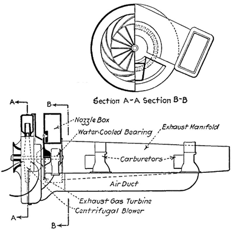 |
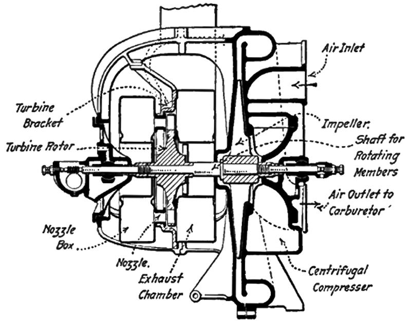
Fig.5. Rateau Turbocharger. Plain bearings were a carryover from steam practice and may have reflected the shortage of ball bearings in France during the period. |
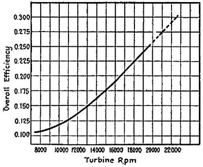
Fig. 6. Adiabatic efficiency vs. turbine rpm curve for a Rateau turbocharger is less than impressive by modern standards. |
Fig.7. Moss turbocharger tested on Pike’s Peak. |
There are reports that, in order to impress skeptical Army engineers with the forces generated by a turbo, Moss arranged for a demonstration at McCook Field. The turbocharger was mounted on a Liberty engine, barricaded behind sandbags. Observers took cover as the engine was started and accelerated to full throttle. With minutes the engine exploded, sending spark plugs through the roof of the test house.
In September 1918, Dr. Moss and his crew journeyed to Pikes Peak carrying with them a turbocharged Liberty 12, a dynamometer and provisions for a six weeks’ winter camp out (Fig. 8). Twenty-five dyno runs were made. Without the supercharger, the Liberty produced 354 hp at ground level and 230 hp at 14,000 ft. The dummy propeller cost about 100 hp at ground level. Supercharged, with the nozzle boxes at red heat, the engine produced 377 hp for 30 seconds before detonation destroyed the spark plugs. During these wide-open-throttle tests Moss hovered over the engine, making adjustments. The crew tied him down with rope to keep him clear of the propeller.
When the war ended, funds for research dried up, although the Army did continue to provide minimal support for the program (Fig. 9). Until the late 1930s Dr. Moss and his five assistants worked out of a single room at the GE West Lynn facility.
In February 1920, McCook Field test pilot Rudolph W. Schroder took a turbocharged LUSAC-11 to 33,113 ft and was still climbing when his oxygen supply failed. He managed to put the plane into a shallow dive before passing out. He regained consciousness at less than 4,000 ft and managed to get the plane on the ground. Schroder, covered with ice, his eyes frozen open, was lifted from the cockpit and taken to the base hospital where he recovered. The next year, Lt. John A. Macready established a new altitude record of more than 34,000 ft in the same plane.
In 1932 the Army fitted a GE turbocharger to an experimental two-place fighter that a year later entered service as the PB-2A. Fifty of these planes, powered by Curtiss Conqueror engines, were purchased. C. Fayette Taylor was responsible for “sidewinder” installation with the turbine extending out of port side of the engine cowl. Cooling was a problem.
In 1937 Moss and his crew adapted the turbocharger to the YB-17, then considered obsolete. Within a year, the bugs had been worked out and the bomber flew faster than most pursuit planes. The turbocharger also made high-altitude strategic bombing possible.
Ben Pinkel, a remarkably gifted engineer, was hired by NACA in 1931 and by 1940 began to work on turbocharger impellers. Figure 10 gives an idea of the progress.
 |
 |
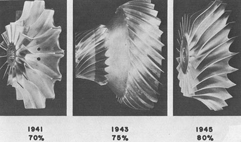 |
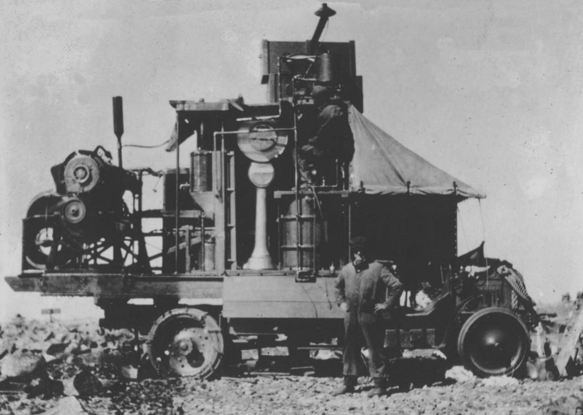
Fig. 8. Equipment Dr. Moss took to Pikes Peak. (NARA) |
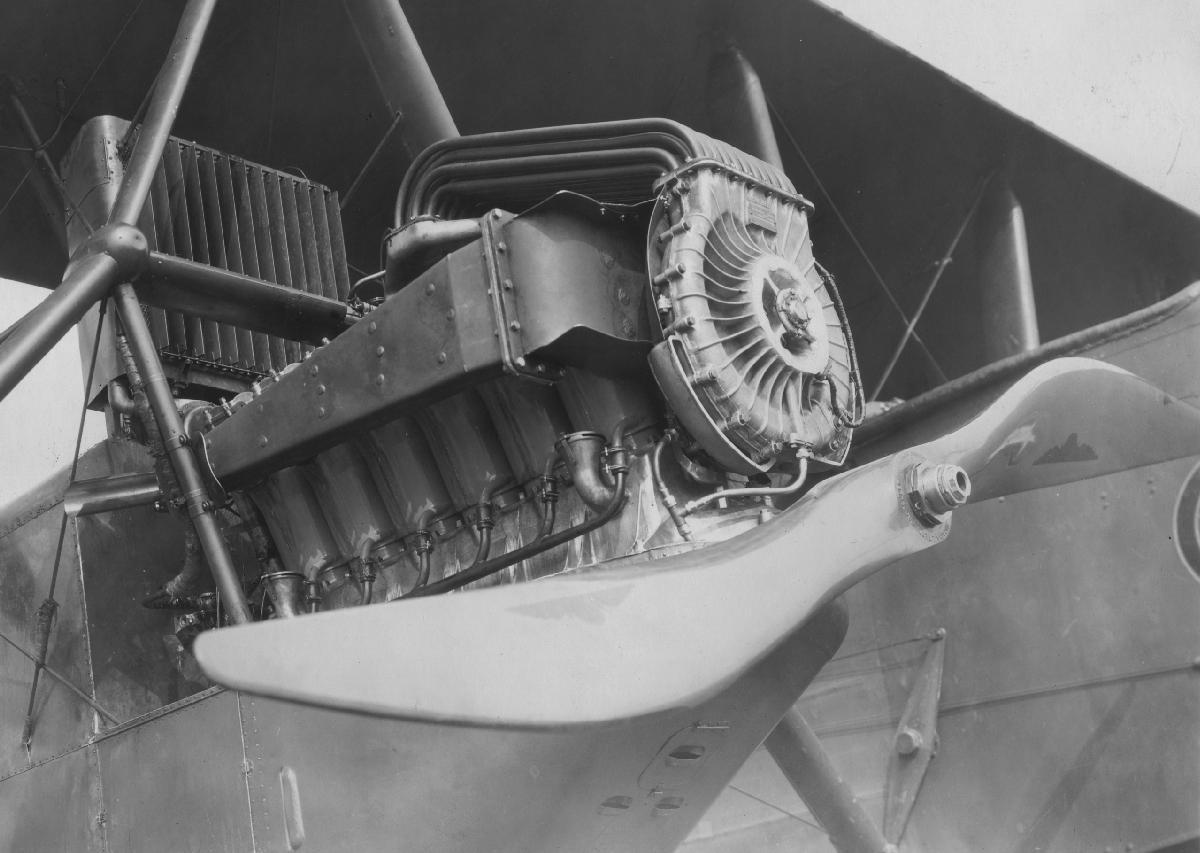
Fig.9. Turbocharged Liberty engine. Moss used a cluster of small-diameter tubes that functioned as a heat exchanger to pres-surize the carburetor, which was positioned downstream of the turbo. (NARA) |
Fig. 10. Progress in efficient impeller design. (NASA) |
Metallurgy
Until the advent of turbochargers few steels would maintain strength, dimensional stability, and fatigue resistance at red heat. Robert Schlaifer goes into great detail about the search for alloys that would enable turbine blades, or buckets, to live. What follows is a summary of his work with some additional commentary.
1918-22 – SAE 6150, a moderately hard, chrome-vanadium spring steel with good fatigue resistance. Ford used 6150 or a similar vanadium steel for Model T chassis members.
1922-28 – Silchrome No. 1. Less scaling than SAE 6150; used in the recent past for Ford 351 intake valves.
1928-33 – KE 965. An austenic nickel-chrome stainless steel developed in England for exhaust valves. Resists scaling and has good hot tensile strength (34,400 psi at 900° C). Applications included valves for the Rolls-Royce Griffon and high-performance motorcycles. Finds application today as a decorative steel.
1933 – 17W. The American equivalent of KE 965.
1933 – Stellite 6. A cobalt-chrome alloy developed by Frederick Taylor at the turn of the century for the high-speed cutting tools. Although brittle, Stellite 6 has excellent abrasive resistance and hot-strength properties. It was too hard to forge, but Austenal Laboratories had devised a lost-wax casting process for making artificial dentures out of Stellite 6. To better market their stainless-steel false teeth, the company called the material Vitallium. But turbine blades were a more demanding application and GE continued its search for a steel that was both durable and forgeable.
Late 1930s – 1941. Stellite 21. The war-time demand for turbine blades made forging impractical. Austenal Laboratories came to the rescue with a modified lost-wax casting process for Stellite 21, a nickel-chrome-molybdenum alloy not very different than Vitallium. From late 1941 the material became standard for turbine blades, both for turbochargers and early jet engines. Modern applications include medical equipment and hard-facing for forging dies.
These advances in metallurgy were not widely appreciated, even at GE. Shortly before retiring in 1938, Moss proposed that the company develop a turboprop engine. A turbine inlet temperature of 1,700° F would be required to obtain reasonable fuel economy. The engineer who evaluated the proposal thought that 1,700° was more than steel could endure. For this and other reasons, management turned down the proposal. Moss then summoned the “young upstart” to his lab at West Lynn and showed him turbocharger running at that temperature.
Roots Blowers
At WW1 came to close, NACA initiated a long and quixotic campaign to transform the Roots blower into a supercharger. While no aircraft engine maker adopted this form of supercharging, the work was not entirely wasted. Experience with Roots blowers led to a better understanding of forced induction, which the agency put to good use during the Second World War. Oscar Schey, head of NACA’s supercharger group, became an internationally recognized authority on the subject.
Somewhat ironically, Roots blowers have since become the most popular type of supercharger for motor vehicles. Between 1989 and 2006 the Eaton Corporation manufactured 3.5 million three- and four-lobe blowers for Ford, General Motors and dozens of foreign manufacturers. Production currently runs at almost a million units a year.
The blower came to NACA by way of George W. Lewis (1882-1948). In 1919 Lewis was the second person hired by the agency and five years later moved up to become director of aeronautical research, a “title that designated what he had been almost from the start.”[4] Lewis would hold this position until retirement in 1947.
When Lewis was hired, he brought with him drawings for a Roots blower he had designed, or oversaw the design of, during his previous tenure at the Clarke Thompson Foundation. NACA had blower built and almost immediately began testing it on a Liberty engine.
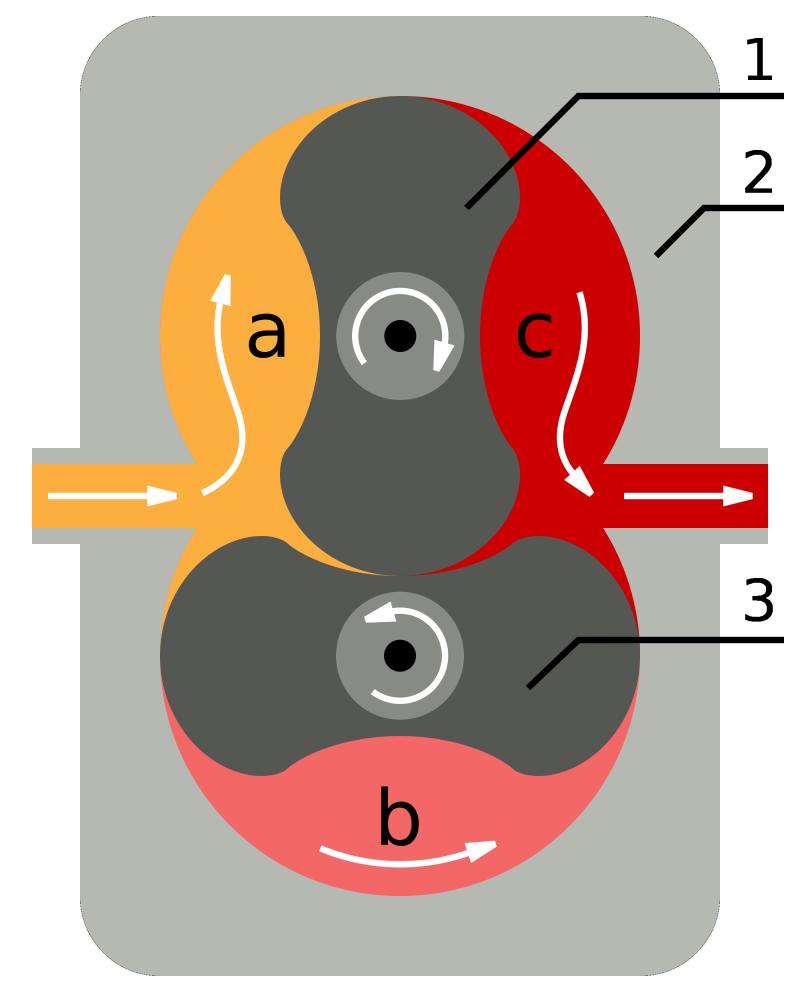
Operation
A Roots blower can be thought of as an elementary gear pump with only two teeth on each wheel, or rotor (Fig.11). As the rotors turn, they mesh with each other to convey air from the inlet to the exhaust port. Note that the rotors merely move air without compressing it. Compression takes place as discharged air collects in the intake manifold more rapidly than the engine consumes it. Centrifugal pumps perform the work of compression prior to discharge, which is a more efficient process that results in less charge heating.
The Roots blower operates in four phases:
Expansion – air enters under atmospheric pressure and expands to fill the low- pressure cavity “a".
Dwell or seal – the incoming charge, trapped in the cavity formed by the rotor and housing, moves toward the discharge port “b”.
Backflow – as a rotor uncovers the discharge port, manifold pressure momentarily forces air back into dwell cavity.
Discharge – the incoming charge, now under manifold pressure, is forced through the discharge port “c”.
The clearances between rotors and between the rotors and housing must be close enough to isolate each phase from the succeeding phase and loose enough to allow for thermal expansion of the light-metal parts. In addition, the pressure variations between backflow and discharge phases generate large pulsations in the intake manifold that, to one degree or another, compromise carburetor metering. During early tests, NACA attempted to dampen these pressure waves with a large tank-like receiver downstream of the blower.
Roots blowers are classified as constant-volume pumps since each revolution of the rotors should theoretically deliver the same volume of air. Boost increases linearly with engine rpm without the “lag” characteristic of turbochargers and, to a lesser degree, of geared compressors. Instant response is one reason why auto engineers favor the Roots blower.
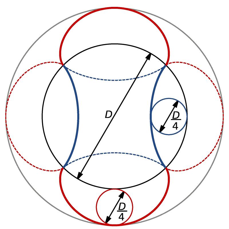
Geometry
The profile of a two-lobe rotor derives from cycloid curves generated by a selected point on a circle rotating around the periphery of a larger base circle. As shown in Figure 12, the generating circles for two-lobe rotors are normally one-quarter of the diameter of the base circle. Rotating the generating circle along the inner periphery of the base circle generates the hypocycloid curve that forms the central section, or waist, of the rotor. The epicyclic curve of the rotor tips comes about from rotating the generating circle on the outer periphery of the base circle. The housing is made up of two intersecting cylinders, each of rotor diameter and separated by rotor center distance.
 |
 |
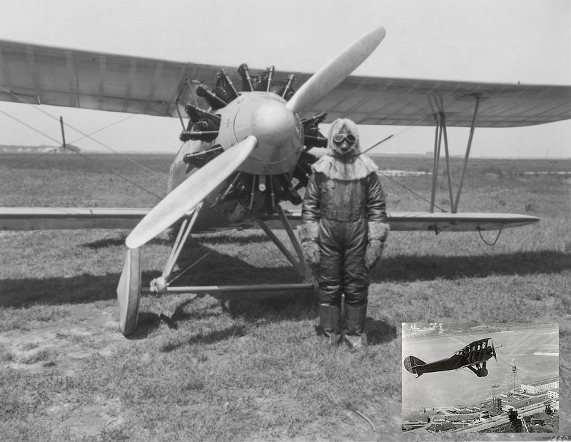 |
Fig. 11. Roots blower operation. (Wiki Commons) |
Fig. 12. Roots geometry. (Wiki Commons) |
Fig. 13. The Wright Apache that Lt. C.C. Champion used for his record-breaking flight in 1927. (Wiki Commons) |
NACA Blowers
If NACA blowers had any claim to originality, it was because Lewis or his assistants had made diameter of the rotor generating circles larger than one-quarter of base circle diameter. The trajectory described by rotor tips no longer exactly followed the curves of the mating rotor. This modification increased displacement by about 6% and introduced a small amount of in-housing compression.
The original NACA blower had 9.5”-diameter, 11”-long rotors that gave a displacement of 879.5 in³. Geared to turn 1.5 times crankshaft speed, the supercharger was designed to raise the critical altitude of a Liberty engine to 15,000 ft. With its light-metal case and rotors, the blower weighed 88 lb, or about a quarter of an equivalent commercial type. However, the overall weight of the installation could approach 200 lb, a figure that does not include the auxiliary radiator that was sometimes fitted.
Concerns about torsional vibration led NACA to insert a flexible Thermoid coupling between the engine and blower assembly. Ahead of the coupling was a tapered shear pin designed to fail in event the supercharger seized. Alloy-steel spur gears provided the speed multiplication and, like the rotors, ran on ball bearings to reduce friction and eliminate the need for forced lubrication.
By late 1927, the agency had two smaller blowers constructed, with impeller lengths of 4” and 8.25”. Rotor diameter and profile was the same as used on the original design. NACA subjected the blowers to a series of ground tests at Langley to measure the effects of rpm and displacement on air delivery.[5]
Test Results
NACA went on record in support of the Roots blower with an article published by the Society of Automotive Engineers in 1926. “A Roots-Type Aircraft Engine Supercharger,” was written by Arthur W. Gardiner, who had worked with Lewis on blowers at Clarke Thompson and who then headed up NACA operations at Clark Field.
The data was dramatic. At speeds of between 600 and 1,000 rpm, the NACA blower exhibited an adiabatic efficiency of 75% at a pressure ratio of 1.6. Efficiency dropped to 65% at a pressure ratio of 2.0, which corresponded to full pressurization at 18,000 ft.
The blower enabled a DH-4 to reach an absolute altitude of 20,800 ft, a gain of 92% over natural aspiration. The service ceiling doubled and the time to reach 16,000 ft was reduced from 32 minutes to 19 minutes.
Another series of tests was run on UO-1, powered by a Wright J-4 engine. The blower increased the absolute altitude of the aircraft by 66% its service ceiling by 71%. At no time did cylinder head temperature reach 500° F, which Heron had defined as the maximum permissible limit.
The high point came in 1927. Flying a Wasp-powered Apache with a NACA blower as first-stage supercharging, Navy Lieutenant Lt. C.C. Champion, Jr. established a new altitude record of 38,418 ft (Fig. 13). The record would stand for two years.
As early as1931, NACA engineers recognized the superiority of the turbocharger at altitude As Oscar W. Schey wrote,
“[F]or altitudes of up to 20,000 feet, when ideal methods of control are employed, there is very little difference in superchargers from the point of view of net engine power, while for critical altitudes of over 20,000 feet an engine develops more power when equipped with an exhaust turbosupercharger than with any other type. The Roots supercharger, because of its less efficient type of compression gives lowest engine power.[6]
Power at Altitude was the Reason for Supercharging
Nevertheless, NACA continued to support the Roots blower until 1942, although Schey, who was in charge of the project, broadened the scope of work to fuel injection, valve timing and other aspects of forced aspiration. When Lewis visited Germany just before the war, he was surprised to find copies of Schey’s reports in offices of the Deutsche Versushsanstalt fur Luftfahrt.
In 1938, a door cracked open to the future. Two NASA engineers, Eastman Jacobs and Eugene Wasielewski, set out to design an axial-flow compressor. Jacobs, whose work on boundary layer control led to the low-drag airfoils used the P-51, was intrigued with the flow problems the device offered. Early tests were encouraging, but when the compressor shed its blades, Jacobs abandoned the project. Wasielewski persevered, but was unable to achieve better pumping efficiencies than obtained with existing GE turbochargers. James Hanson in his history of NACA suggested that the device may have helped convince American manufacturers of jet engines to substitute axial-flow for the centrifugal compressor used by Whittle.[7]
Conclusion
Supercharging aircraft engines was a difficult endeavor involving numerous incremental steps. Progress in compressor and turbine design came about through the accumulation of knowledge about fluid flows, metallurgy and fabrication techniques.
References
1. “He Harnessed a Tornado and Developed the Modern Airplane Supercharger,” Popular Science, June 1941.
2. Sherman, Donald, “Hill Climb,” Air & Space Magazine, May 01, 2001
http://www.airspacemag.com/history-of-flight/climb.html
3. “He Has Harnessed a Tornado,” Popular Science, June 1941.
4. Roland, Alex, Model Research: The National Advisory Committee for Aeronautics, 1915–1958. (NASA SP-4103, 1985)
http://history.nasa.gov/SP-4103/sp4103.htm
5. Ware, Marsden and Ernest E. Wilson, “The Comparative Performance of Roots-type Aircraft-Engine Superchargers as Affected by Change in Impeller Speed and Displacement,” NACA 284, Dec., 23, 1927)
6. Schey, Oscar W. and Young, Alfred W., “Comparative Flight Performance of Airplanes Equipped with Supercharged Engines,” NACA Technical Report No. 355, 1931.
7. Hanson, op. cit.
Send mail to
![]() with questions or comments about this web site.
with questions or comments about this web site.
![]()