
")


Daimler-Benz Aircraft Engines
Daimler-Benz 600-Series Aircraft Engines
From the National Archives of the United Kingdom at Kew, thanks to Dave Birch
|
|
|
|
|
|
|
|
|
|
|
|
|
|
|
|
|
|
|
|
|
|
|
|
|
|
Improving the Mercedes
Performance Increase in the db601 Engine, circa 1940
by Jerry Wells, 2007
 |
 |
On September 7th, 1940. Reichmarschall Goring summoned two of his leading fighter pilots, namely, Galland and Molders to his newly established headquarters at cape Gris Nez on the English Channel coast. Basically, he wanted to know why German Air Force bomber losses over England were so high. After some acrimonious discussion, Goering asked for suggestions regarding technical equipment improvements. Galland got himself into trouble by requesting Spitfire aircraft; Molders sensibly asked for fighter aircraft with more powerful engines.
At Daimler-Benz, efforts to increase the power of the V-12 Mercedes engine proceeded along two lines — first, by improving aspects of the basic 33 L (2,070 in³) engine to produce the db601E and second, by increasing the capacity of the motor (in addition to the improvements) which resulted in the D 605A model of 35.8 L (2,180 in³).
The aspects of the db601A engine focused on can be summarized thus:
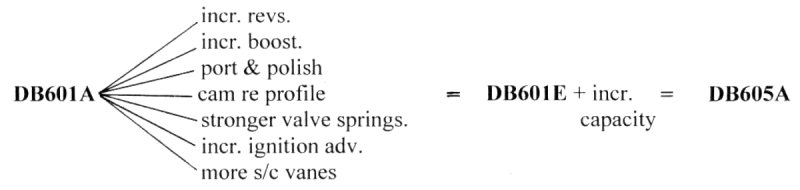
Permissible revs for the 601A were 2,400 rpm, this limit was raised to 2,700 for the 601E and pushed up to 2,800 for the 605A. The 601E retained the distinctive roller bearing big-end feature but this was abandoned for plain shell bearings in the 605A. This may have been done to cope with increased lubrication requirements at the higher rpm.
Since the use of high boost pressures was not favoured by German engineers due to the elevated induction temperatures involved and piston weakness, the 1.3 ata (38.8 inHgA, +4.25 psi gauge) limit for the 601A was increased to only 1.42 ata (41.3 inHgA, +6 psi gauge) for the 601E and 605A. To achieve this, the supercharger impeller was given an extra four vanes, to give a total of 16 (see Fig. 1) and for the 605A, the impeller diameter was expanded from 10.24” to 10.47”.
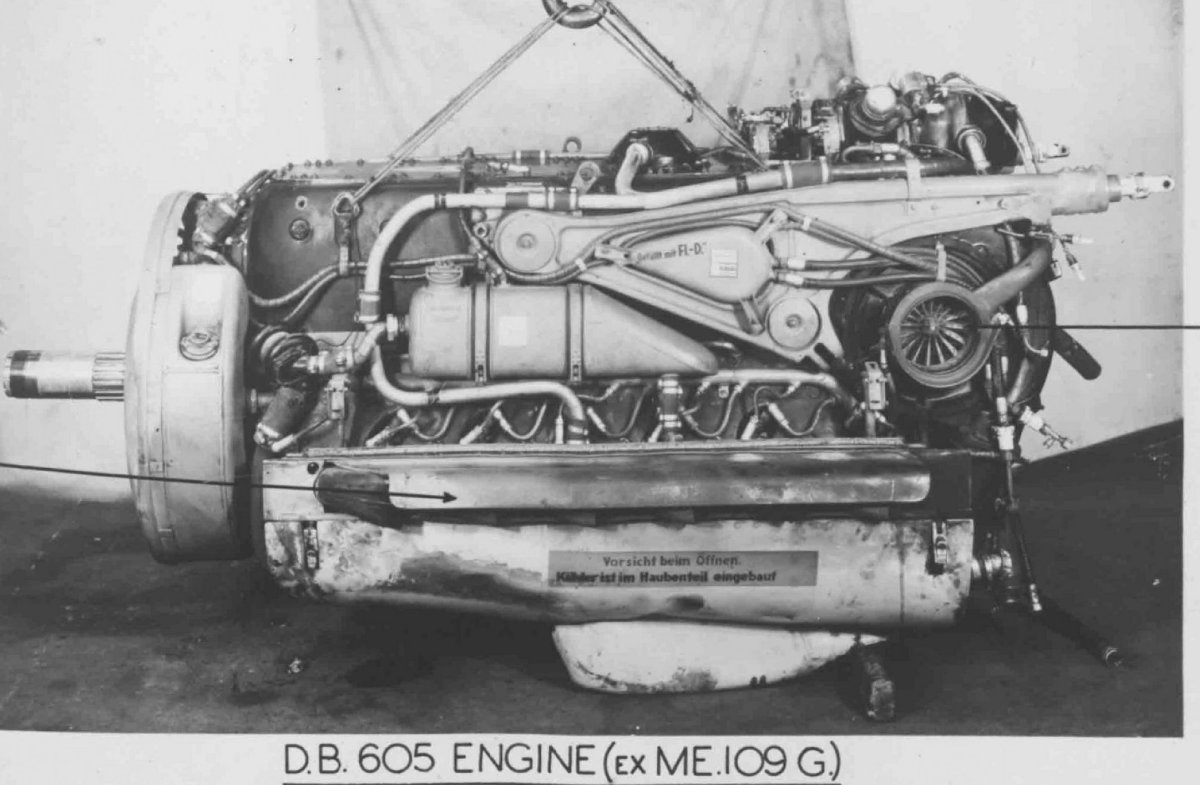 |
| Fig. 1. This engine still has the coolant and oil tanks fitted. The lower cowling panel with integral oil cooler air scoop is also on the engine. This cover hinges on the right-hand side and opens by release of the two catches visible at either end of it. The notice on the cowling says, Vorsicht biem Offnen (Caution near opening!) and Kuhler ist im Haubenteil eingebaut (Radiator is mounted in the cowling panel). |
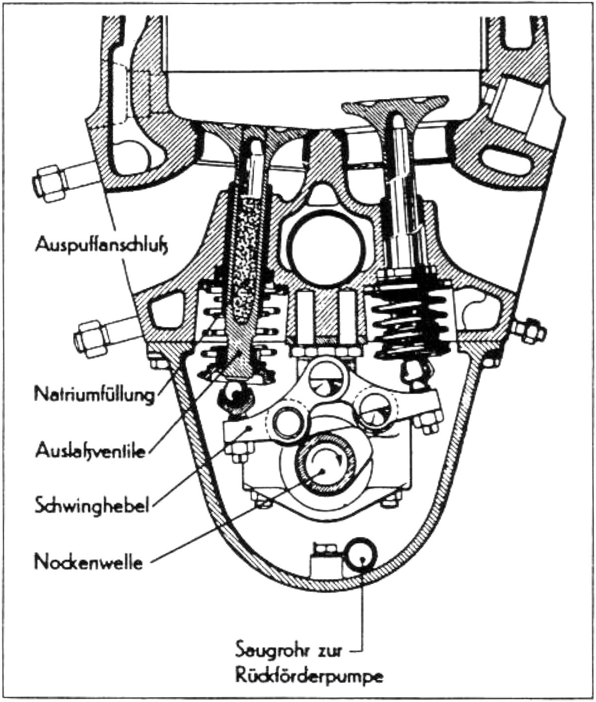
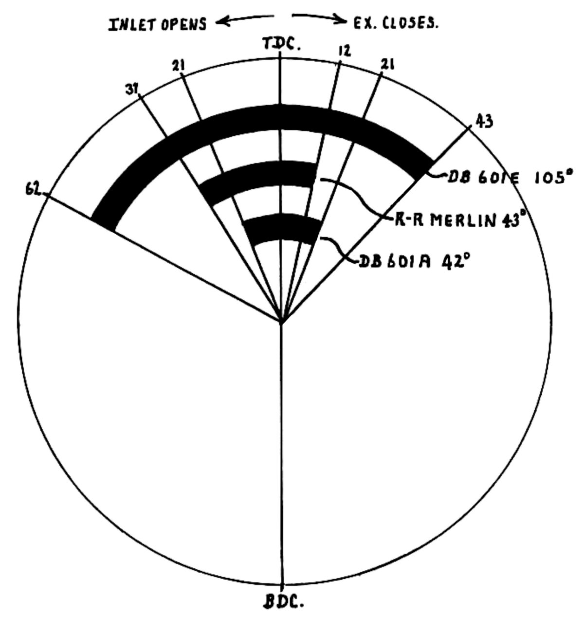
The most radical change involved the valve timing. The 601E and 605A were fitted with what would be described today as fairly "wild" camshafts which acted to hold both inlet and exhaust valves open for no less than 105° during each exhaust/intake stroke. This represents 150% increase in the overlap (see Fig. 2) compared to that of the 601A! To aid the gas flow, there was a general cleaning up of the induction passages and lengthening of the inlet port laces so that the air flow path was much less obstructed by the partition walls between and around the individual ports. On top of this, the ignition spark timing was advanced another 10°, from 33° BTDC to 45° BTDC.
 |
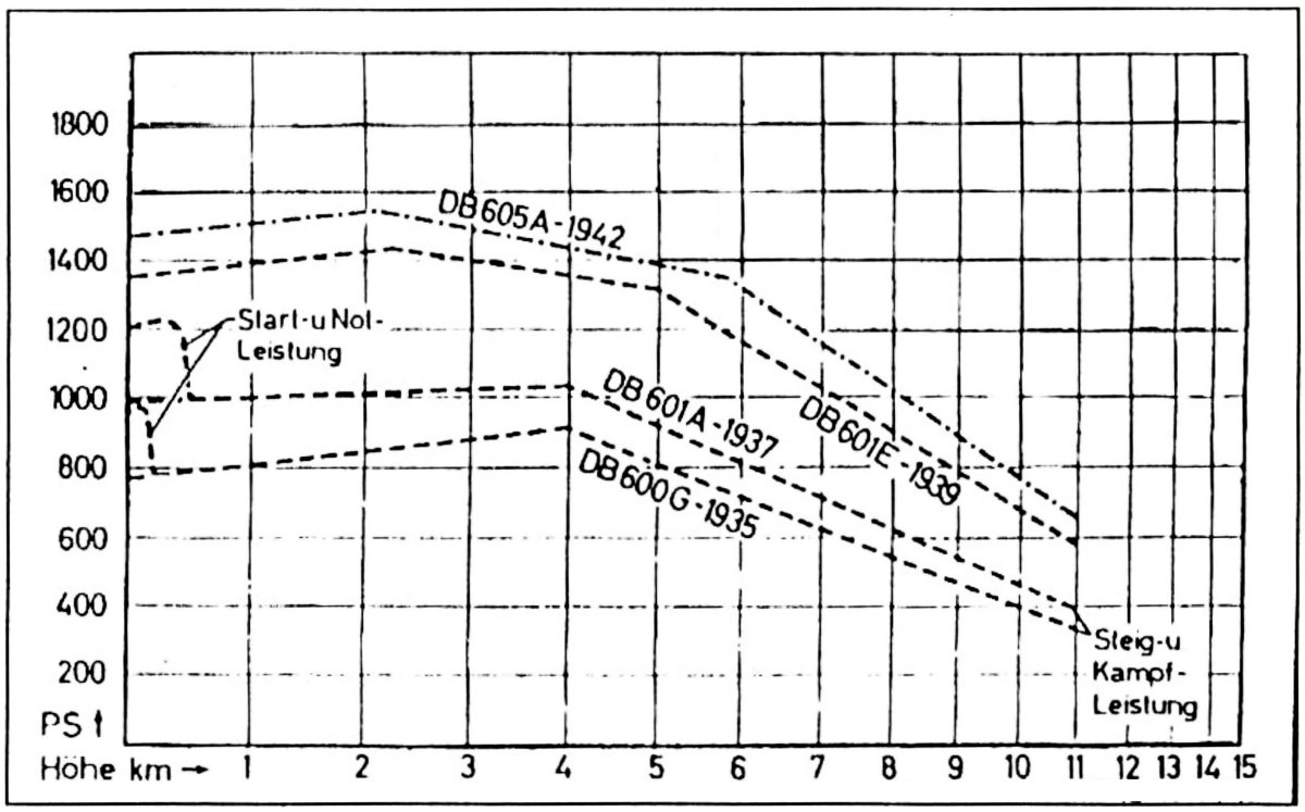 |
| Fig. 2. Part of the timing diagram to show the huge increase in valve overlap used in the db601E and db605A. | Graphs showing performance characteristics of db601 and db605 engines. |
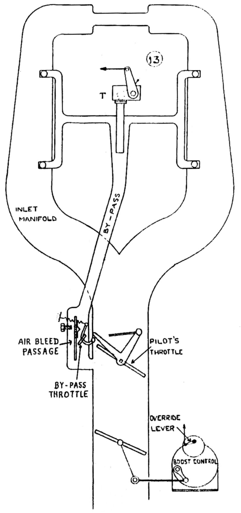
As many of us know from our "hot-car" days, there is a price to pay when a "wild" cam is installed in an engine — its low speed performance deteriorates and the idle is lumpy. The low speed characteristics of the db601E/605A were so bad that a special low speed intake system had to be added. In these engines, a by-pass passage across the main throttle was necessary to allow accurate setting of the intake air how when the main throttle was closed and this air was distributed evenly to the inlet port face of each cylinder bank. (see Figs. 3 and 4 ). This miniature induction system was grafted onto the main system. The auxiliary passage was provided with a throttle, cam operated by the main (pilot controlled) air throttle during the last few degrees of the latter's closing motion. This little throttle was normally spring loaded in the full open position but provided a sensitive control on the air flow at slow running speeds, while the final setting for satisfactory idling was made by the usual type of screw restrictor in a further air bleed passage
All the changes resulted in an increase of about 250 HP.
References
Royal Aircraft Establishment, Farnborough, U.K. Report No. EA. M/116. 1943.
 |
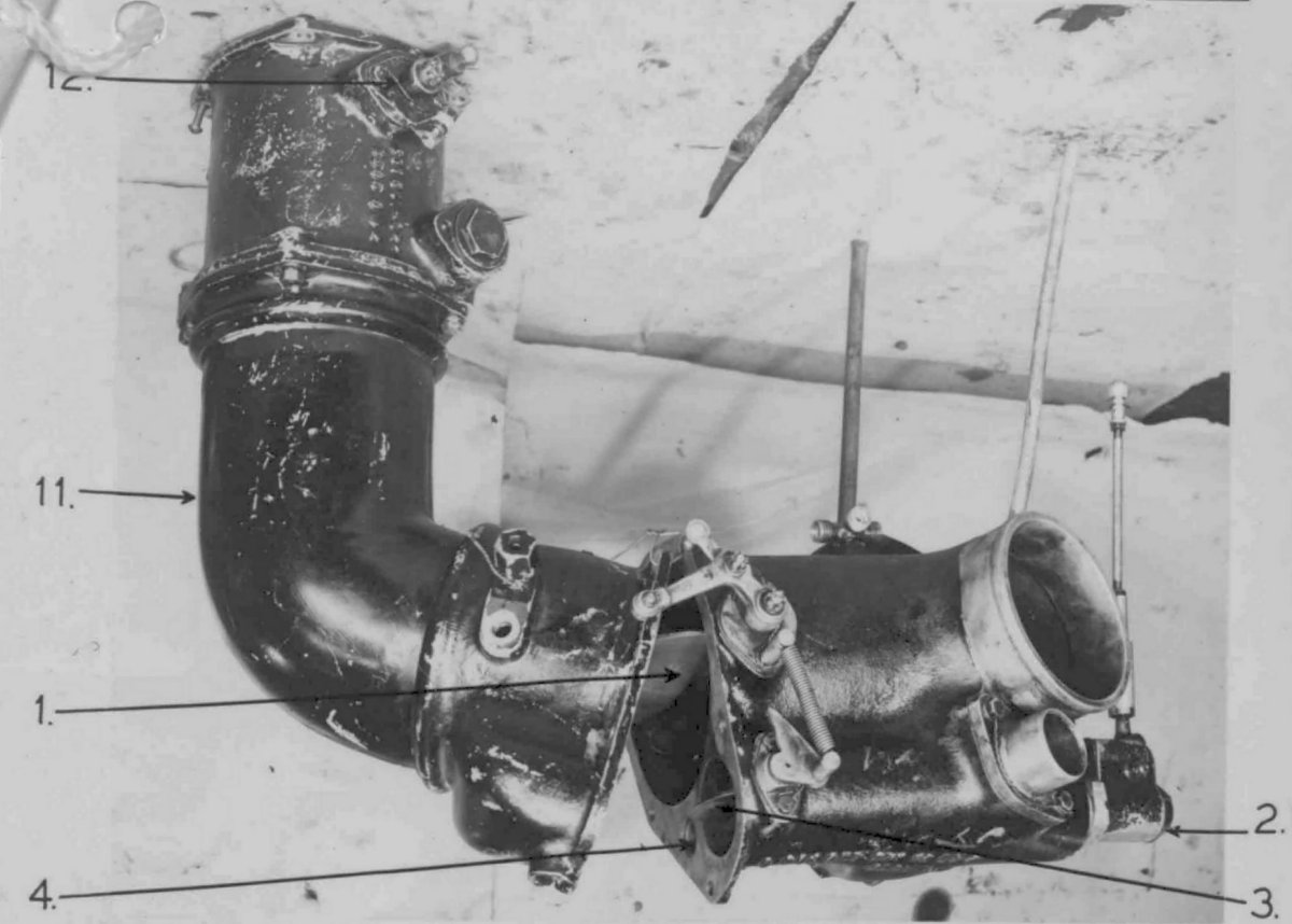 |
| Fig. 3. Schematic drawing to show the layout of the main and auxiliary induction pipes. | Fig. 4. Part of the induction tract dismantled. Main and auxiliary branches to right-hand side cylinder bank can be seen to the right of the photo. (12 = boost control throttle, l = pilot controlled throttle, 3 = by-pass throttle, 4 = air bleed passage, 2 = thermostat) |
Send mail to
![]() with questions or comments about this web site.
with questions or comments about this web site.
![]()