(National Museum of the US Air Force)
The Making of a Flight Engineer
Part 3: Stateside — C-124s
by Floyd J. Stelly
|
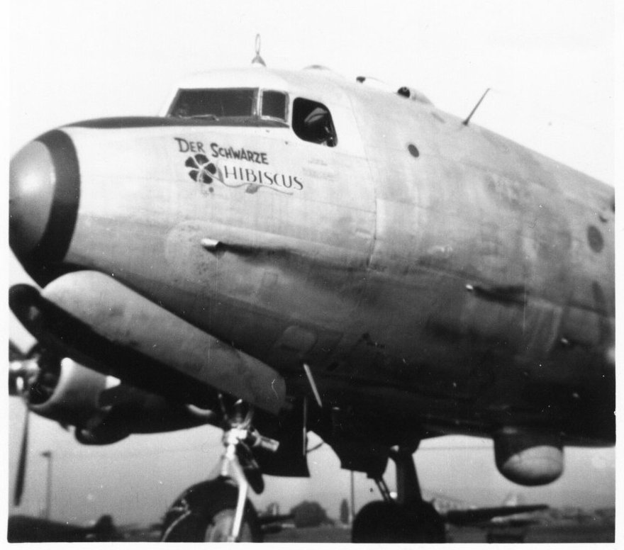
| Douglas C-124C Globemaster (National Museum of the US Air Force) |
After spending five months at Chanute Air Force Base learning cruise control and systems on the C-124 aircraft, I was sent to Moses Lake, Washington for flight training as a flight engineer. We flew the C-124 A and C models. The A model had the R4360-20W engine, which produced 3,500 brake horsepower wet. The C model had the -63A engine, which produced 3,800 horsepower wet. The Air Force modified the A models with radar and a -63A engine and re-designated the aircraft as C-124C.
The early models had a forward-facing flight engineers station behind the copilot in a separate compartment with the radio operator and navigator. The captain and copilot had their own compartments with a door. I liked this arrangement because at night we could keep all the bright lights on without interfering with the pilot’s vision.
Later models had a side-facing engineer’s panel and everything was one large, open compartment. Pre-flight included the usual walk-around, checking fuel and oil quantities. The fuel system was pressurized and the scanner or second engineer entered the wing crawlway to the engine firewall door and checked for leaks. Outboard nacelles also housed two Auxiliary Power Units (APU). This nacelle was large enough that the average-sized person could stand upright without a problem. In flight, the inboard nacelle entry was cramped because you were between the two retracted landing gear tires.
All communications and checklists were usually done over the interphone system. We wore headsets with boom microphones. The flight engineer had a foot-operated microphone switch so he could speak while using both hands, such as during engine starts. After pre-flight, the engineer contacted the control tower for the temperature and dewpoint, runway in use, and wind direction. The engine power was then predicted along with the V1 and V2 speeds for the gross weight. Because the engineer had no windows and could not observe the engines, the engine start process was coordinated with ground personnel (scanners) communicating via the interphone system. The scanner counted off the prop blades, usually eight, after the starter engagement. The flight engineer watched for oil pressure indication while switching the magnetos to both. The primer was held on and engine usually started firing. While running on primer, mixture was moved to Auto-Rich. When a slight drop in RPM indicated carburetor mixture had taken over, the primer was released.
If the start was unsuccessful, the scanner would call out "dry" or "wet" to indicate whether fuel was coming out of the super charger drain valves. The copilot read the Taxi and Before Take Off Checklists. Before departure, all controls were checked, the engines run up, magnetos checked and the props exercised. The Take Off Checklist was read as we taxied into position.
Anti-detonation injection (ADI) was turned on and cowl flaps closed in take-off position as we started applying power. The pilot making the take-off calls "take-off power" as he was advancing the throttles. When power was set and predicted torque (torquemeter) pressure was achieved the flight engineer called "power checks OK". At V1 speed if everything looked normal he called out again "power checks OK".
An engine failure before V1 speed meant the take off could be aborted safely and the aircraft stopped before the end of the runway. A failure after V1 speed meant that the take off would proceed followed by return to landing with the propeller feathered. The first power reduction was METO (Maximum Except Take Off). ADI was turned off, then climb power was set until the assigned altitude was reached.
After leveling off and speed was stabilized the cowl flaps were further closed. Speed for maximum range was calculated from a chart, which showed gross weight and brake horsepower to maintain the best nautical mile distance per pound of fuel burn. From this brake horsepower, we calculated the RPM, manifold pressure and torque pressure. As the gross weight decreased, power was reduced to maintain the maximum range air speed, which usually averaged about 170 knots. Fuel tracking was used from start of taxing to landing.
The engine analyzer was used to check spark plugs approximately every thirty minutes or whenever the torque pressure gauge showed a suspected problem. Every hour we placed the mixture control in Auto-Rich and held the primer on for one minute. This was to shock cool and de-foul any plugs that were accumulating too much lead. The 115-145 octane fuel contained about 4½ CCs of lead per gallon. This system worked well because I had very few fouled plugs.
About once an hour the scanner would go to the lower compartment and open the doors to the wing crawlway and check for smoke or anything out of the ordinary. The flight engineer station always had to be manned because of the electric propellers. Occasionally one propeller would start hunting up and down and you could have a runaway condition. The procedure was to take that prop out of automatic and place it in the off position, then to use the Increase/Decrease switch to set the RPMs. Any abrupt throttle movement could also cause the prop to surge. Hamilton-Standard Hydromatic propellers on the C-119 aircraft responded much better.
We very seldom ever used the high-blower supercharger position because the high gross weight and a need for cooling passenger oxygen at the higher altitudes. Also, the cylinder head temps run a lot higher at altitudes. Contrary to what I’ve read, the R-4360 did not run hot on the ground, especially during taxing and take off. Even the R-4360 and C-119 ran relatively cool. The propellers had cuffs, which directed more air into the cowl and kept the temperature down. The corn-cob cylinder arrangement of the R-4360 also allowed more exposure of cylinder fins to cooling air.
The fact that the C-119 and C-124 were non-turbo charged also had a lot to do with keeping the temperature down. The fuel system on the C models C-124 had 12 fuel tanks with electrically operated fuel valves. Earlier models had six mechanically operated valves. Fueling was center-point below the wings. Oil capacity was 82 ½ gallons per engine and burned about 2 gallons per engine per hour, average. Two 30-gallon ADI tanks supplied all engines for about five minutes at maximum power.
Descent and landing was fairly straightforward with power reduced to minimum until on final approach, then RPM was set to 2,600 in case of a go-around. After touchdown, propellers were reversed. The brake system was the expander-tube type and need all the help it could get if the runway was short. The two APUs were remotely started and put online before the engines were shut down.
Most of the missions I flew were cargo and dropping paratroopers. We could carry 200 paratroopers or 120 litters. My longest mission was 13 hours from Puerto Rico to Rio de Janeiro, Brazil to deliver two helicopters. Returning to my base at Greenville, South Carolina, we proceeded to Canada to deliver cargo for the Distant Early Warning Network (DEW Line), installed to detect unfriendly aircraft flying over the North Pole toward the US. We landed this cargo on the frozen lakes, opened our cargo doors, lowered the ramps, and discharged the cargo without shutting down the engines. Closing the doors, we quickly departed. This wasn’t the place that you wanted to be if an engine wouldn’t start.
After a short stay in Canada and with my discharge date from the Air Force coming up soon, I ferried an aircraft back towards Donaldson Air Force Base, South Carolina. Clearing the base, I returned to my home in Louisiana and started applying for a job as flight engineer with the airlines.
For more information about the C-124, including great images, please visit The Aviation Zone C-124 Page
Part 1: C-54s, DC-4s and C-82s in Europe
Part 2. Back Stateside – C-119s from Miami to Greenland
Part 4. Airline Experiences – Lockheed Constellations, Douglas DC-6s and DC-7s
Part 5. Airline experiences – Lockheed L-188 Electra
Part 6. Airline experiences – Turbojets
Send mail to
![]() with questions or comments about this web site.
with questions or comments about this web site.
![]()