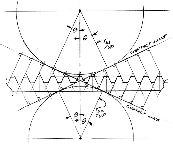
Fig. 1. The Straight Tooth Involute Rack
(From base circle contact line geometry)
Gearing for Gearheads
by Phillip Miller
The AEHS is pleased to present Phil Miller's monumental analysis of the Rolls-Royce Merlin propeller speed reduction unit in its entirety. Below is additional material that did not appear in the Torque Meter articles, along with the Microsoft Excel Worksheet used to calculate gear parameters.
Gearing for Gearheads, Part 1 (333K PDF), from Torque Meter Vol. 5, No. 1, Winter 2006
Gearing for Gearheads, Part 2 (559K PDF), from Torque Meter Vol. 5, No. 3, Summer 2006
Gearing for Gearheads, Part 3 (613K PDF), from Torque Meter Vol. 5, No. 4, Fall 2006
Microsoft Excel Worksheet that Calculates Spur Gear Parameters
More on Shifted (Offset) Addendum/Dedendum Changes to Tooth Thickness
The linear nature of involute racks and straight cylindrical hobs yields a pleasant surprise. A normal offset of e inches while maintaining the former rotational relation of generating tool and gear or pinion blank causes a thickness change of e times the tangent of θ \(the contact angle) to each involute flank of the teeth without changing the pitch diameter. Thus offsetting rack or hob e inches outboard causes a total pinion tooth thickness increase of 2e times the tangent of θ. Offsetting rack or hob e inches inboard similarly reduces gear tooth thickness by 2e times the tangent of θ.
This operation also causes a shifting of addendum and dedendum (or root diameter) and hence one of its popular names. A narrowing of the teeth, typically employed on the less vulnerable (larger) gear, is accompanied by an increase in the dedendum (a decrease in the root diameter in the King’s English) and a decrease in the addendum and OD. These dimensional changes are equal to the offset e.
Excessive narrowing of gear teeth COULD weaken this usually less vulnerable larger component dangerously. Hence if there is any doubt, as when such thinning exceeds the bounds of experience, it is worthwhile to subject this larger component to the analytical scrutiny normally reserved for the pinion.
It appears that the 0.420 ratio Merlin gearing involves this sort of shifty manipulation. The earlier 0.477 gearset and PSRU exhibits evidence of tooth thickening and thinning of a more elegant though somewhat ALIEN nature. This will be discussed later.
Now do y’all believe this? A born doubter and very reluctant to accept ANY engineering "Truth" on blind belief, I stumbled hard on the proclaimed constancy of the pitch diameter through all of these manipulations. I pondered and sketched a bit, traced through the round gear’s relation to the straight rack in figure 1 and finally saw clearly the genderless reproductive capability of involute gearing.
|
|
Fig. 1. The Straight Tooth Involute Rack |
We’ll start with the two base circles and diagonal mutual tangent of meshing involute spur gears but this time we’ll add the OTHER diagonal mutual tangent of reversed rotation or reversal of driving and driven roles. The meshing involutes contact one another ONLY on mutual (shared) straight-line tangents which are perpendicular to the mutual diagonal base circle tangents or contact lines. It is obvious from the contact lines’/diagonals’ attitudes (base circle to base circle) that the mating involute surfaces are each swept from base circle to OD along a moving contact point/shared tangent which is always perpendicular to a contact line.
Thus EACH meshing (or intended meshing) involute DEFINES (or as a cutter, reproduces) its mate as the meshed involutes rotate about their base circle centers. This leaves us with the question of a straight rack’s equivalence (in reproductive terms) to a circular gear shape. We’ll return to our double diagonal meshing involute diagram and note that a meshing rack travels normal to the base circles’ common centerline and not along a mutual diagonal or contact line. We drew its bottom line accordingly and a bit to the outside of the mating circular gear or blank OD.
A straight based and straight sided tooth equipped rack now miraculously appears when, with some regard to probable tooth pitch, we extend tangents denoting perpendiculars to the contact lines well beyond the rack bottom line. We truncate the rack tooth and adjacent spaces appropriately and note that the rack straight tooth faces are at angle θ (contact angle) to the original base circles’ mutual centerline thus duplicating the service or utility of a round gear shape.
The rack, its rough equivalence in hand, is seen now with confidence as illustrating as well the general case relation of offset e (eccentricity?) to tooth thickening and thinning. The achievement of constant pitch radius (and diameter) is also clearer in mind knowing that the rack tooth straight sides are all at plus or minus Theta (the contact angle) and realizing that this contact angle will be replicated by the cutter in the circular gear blank where the local radius tangential velocity matches the translational velocity of the rack. The involute tangent angle to the tooth centerline is, of course, equal to the contact angle at the pitch radius and this is in fact definitive.
The requirement then is: The intended pitch radius tangential velocity of the circular blank must equal the translational velocity of the shaper rack or the functional advance rate of the helical cylindrical hob in order to maintain the pitch radius and diameter as constants when machining shifted addendum/dedendum gears.
Textbooks of the Merlin era refer to this offset technique with hobs and straight rack shapers but I found no reference to this practice with the Fellows Gear Shaper which uses an involute gear shaped shaper tool. However it appears that it would work well if a velocity match between tool pitch radius and blank intended pitch radius tangential velocities was enforceable by the gear shaper machine tool.
Gear Production Considerations
The four production/tooling approaches typical of the Merlin’s era and their use or avoidance of these characteristics is also interesting (to Gearheads at least).
The oldest method perhaps started with the ancient Greeks. It is said that their very impressive sculptors would start with a rough quarried block of marble and simply chisel away anything that did not look like a fit part of Aphrodite (a favored subject to this day). This means chiseling or rather milling away the material (spaces) between the teeth of a spur gear and those spaces are bounded by the inverse of the involute gear tooth surfaces. We don’t, in milling a spur gear, make any use of the generating reproductivity of the involute. Instead, the radially indexed rotary "chisel" simply makes its way along the gear blank axis replicating the mill cutter tool radial profile in the intertooth space boundaries.
Milling out intertooth spaces with a shaped rotating mill cutter was used for production of cycloidal and composite 14 ½ degree cycloidal/involute spur gears. Tooling to otherwise create these profiles is awkward and problematic. Cycloidal gearing is still used in clockworks and low load devices as it doesn’t incur undercutting and hence handles large reduction ratios well. Production for these applications today may involve milling the intertooth spaces in a stack or even punch and die in a punch press with a deburr finishing operation.
The two next production methods are easier to understand if we remember the horizontal (ram) shaper. This old standby propelled a single point cutting tool across the workpiece which was mounted on the machine table. The table had an Acme screw feed drive and V ways. Table and workpiece moved (were fed) transverse to the cutting tool travel between tool cutting strokes.
The cutting tool holder was on a suspended pivot block which would kick up from tool drag on the reverse or return stroke. It settled back into position with a loud and satisfying CLACK at the start of each cutting stroke.
Remember it now? Well that’s sort of how the rack tool gear shaper and the Fellows gear shaper work, but without the pivoting block tool holder and loud satisfying CLACK.
Instead, the involute straight rack shaper and the Fellows round involute gear like cutting tool have sharp cutting edges and relief clearance on their involute (rack and gear) surfaces. The ram axis with both is likely to be vertical with workpiece and cutting tool both incrementally advanced as tool and workpiece are clear of one another between cutting strokes. The rack shaper cutting tool advances along its length as its workpiece rotates with coordination as covered earlier. Since the rack is not infinite in length it must return to be re indexed and restarted at intervals.
The Fellows gear shaper cutting tool is circular and hence infinite in rotation (as are, incidentally, both work pieces) thus avoiding the stop and re-index time consuming requirement. The workpiece pitch radius tangential velocity is coordinated with tool advance in both cases as previously discussed.
Hobbing remains to be discussed. The hob itself seems best visualized as resembling a helical thread tap complete with flute-gash-created teeth. A sectional view taken normal to helical tooth normal profile and hence off axis to the "tap" itself is in its central span identical to a rack cutter for the same intended gear type and pitch.
The hob is located normal in azimuth or planform to the workpiece radius and skewed in elevation to present its rack tooth profile normal to the workpiece vertically aligned axis. Rotation of the hob simulates the rack shaper translation due to its helical tooth wrap and cuts and generates an involute gear with machine driven axial feed along the workpiece axis (length/face width) much as a tap cuts threads.
Tapered ends of the hob accommodate constant rotation with constant effective translation without excessive depth of initial cut.
The Hunting Tooth Principle
Although it is better described as an ancient practice and it has not been mentioned to or by me in perhaps 50 years, it is not without some merit so we’ll take a closer look.
The "Hunting Tooth" concept is that the numbers of teeth in each component of a gearset should not be whole (integral) multiples of one another. Thus a dimensional error, foreign debris or foreign debris damage or surface wear or pitting on a tooth of one gear of the set does not as often impinge on the same tooth of the mating gear. Early disaster is thus delayed by perhaps and order of magnitude or more as the problem is allowed to smooth out some by "wearing in", yielding locally a bit and/or shedding of offending debris and all this without rapidly repeated blows inflicted on the same mating tooth.
It was an accepted practice some years ago and appears to be honored by intent in the stock Merlin PSRU gearing. Happenstance is no doubt prominent in modified ratio gearsets but they also owe much to the R-R original choice of odd number total tooth counts for their PSRUs. At least one of the Allison PSRU gearset options is an even 2:1 ratio and thus it cannot involve the hunting tooth concept. Comparison would be interesting but unfortunately Allison experience does not appear to be directly comparable for a variety of reasons related to detail design as well as type of service.
Typical Tooth Failures in Service
One shot gear tooth failure in a PSRU is unlikely barring, possibly, landing gear retraction during ground run-up with a really stout propeller. One shot failures are even rare in modified cars and trucks that are regularly abused. Examination of massively broken teeth almost invariably shows failure beginning high on the filet radius on the compression side of the tooth and progressing with a set of "beach marks" (think successive surf marks as the tide goes out) to a final rapid failure zone lower on the tension side of the tooth. That is a classical fatigue failure with a rub polished shine between some of the first "beach marks".
What starts these failures on the compression side? Enamored of Brit bikes, modified Ford roadsters and later sporty cars, I first blamed backshifting and "bucking compression". But stateside during WWII any youngster capable of twisting wrenches found ready employment as a mechanic in the civilian marketplace and the same sort of failures were soon seen where backshifting and "bucking compression" (actually bucking throttling losses) were virtually against the prevailing religion.
I proceeded to carry this mystery as a puzzle so imagine my surprise and relief upon finding, fairly early on, the same general phenomena remarked upon by Earle Buckingham in his Analytical Mechanics of Gears. The technique of photo-elastic stress analysis developed roughly contemporary with Buckingham and the R-R Merlin and showed that compression side stress of a loaded gear was appreciably higher than that of the tension side when the tooth center line parallel component (gear separating load) was included. This was logical but not then or now regarded as critically important. Compression loading, in a general sense, is not generally seen as the cause of massive tension failure.
The R-R Merlin gears were not designed in ignorance. They showed wise selection and were developed on the cutting edge contemporary with advances in materials, analytical techniques and test methods. They performed well at their intended task. The compression side anomaly, typical of much nominally satisfactory gearing, at least that of the Merlin era (on both sides of the Atlantic) is certainly of possible academic interest and may point the way to increased capability special purpose gearing.
Summary of the Tooth Section Stress Picture
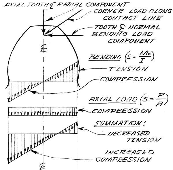
Beam bending stress, by itself, is at a tensile maximum on the load side and at a numerical (absolute) equal maximum compressive level on the opposite side. Tooth radial load, counterpart of gear separation force, adds a uniform across the beam section compressive load. This reduces the tensile stress level on the load side and increases the compressive stress level on the side opposite. It also moves the stress level zero crossing toward the load side from the beam depth midpoint (fig. 2). We end up, to express it crudely, with over half the tooth beam depth in compression and a peak compressive stress exceeding that of the tensile stress. This is supported (now) by years of photo-elastic studies.
 |
|
Fig. 2. The Tooth As A Beam In Bending |
Tension Failures Without Tension?
This is all academic in one sense. When the corner loaded tooth calculated beam bending stress is kept to a reasonable level (based on material properties and corroborating experience) we do not have compression side tension failure initiation. But with ratios and pressure line loads ever increasing, output increasing (turbocharger replacement of the engine driven blower alone could put hundreds of additional horsepower through PSRU gearing) while overall dimensions and gear sizes are effectively limited it seems appropriate to examine compression side failure initiation with an eye to its alleviation. This would hopefully permit full use of the basic longevity of the originally worrisome tension side.
Starting Conditions for Compression Side Tension Failure
The gear material is a steel carburizing alloy heat treated for toughness with a moderately high tensile strength (210 ksi ultimate tensile strength median per R-R drawing Brinell callout). The gear teeth and filet radii surfaces are case hardened to a depth of 0.045-0.055", Rockwell RC-57 to RC-65. (Double oil quenched for martensite conversion and the pinion stress relieved at 160°C for 5 hrs.) The case hardened tooth and filet radii surfaces are ground (0.010" nominal removal) to leave 0.035"-0.045" hardened depth.
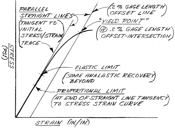
One nominal advantage of case hardening is a surface residual compression stress resulting from the carbon addition occupying tangible volume in the case hardened zone. The subsequent quenching to martensite adds to this surface compression. These effects are slightly reduced but not canceled by a mild stress relief cycle. The conventional and accepted "yield point" of a heat treated steel alloy is determined by the stress strain curve intersection with a 0.2% gage length offset straight line parallel to the initial apparent straight line portion of the stress strain curve. The initial apparent straight line portion of such a stress strain curve may comprise no more than 20%-30% of that curve below the 0.2% gage length offset (elongation) yield point (fig. 3). It is also important to note that gearbox temperatures, even though less than 100°C, will noticeably lower modulus, proportional limit and yield values in actual service.
 |
|
Fig. 3. Generic Stress/Strain Curve |
It follows that some cumulative "permanent set" may be incurred by repeated loading below the accepted yield point stress value. In other words, material adjacent to the compression side of a tooth becomes shorter with continual high tooth loading while the tension side, at a lower stress and the virtually unstressed central tooth portion do not. The bulk of the tooth rules, overall tooth shape is little affected and the small portion afflicted with compression permanent set faces ever increasing residual tension. This is additive to the original residual tension developed as a local equal and opposite reaction to the case hardened zone’s residual compression.
Residual tension increments, aggravated by the cyclic nature of tooth loading eventually lead to crack initiation on the compression side, probably at the relatively brittle case hardened interface. Fatigue crack growth follows while there yet may be no signs of impending disaster on the tension side and little beyond miniscule and virtually unnoticeable case hardened material spall on the compression side. Massive and typical tooth fatigue failure follows.
I was first bitten by this sort of compression permanent set/tension failure/fracture phenomenon in the poured Babbitt bearings of the severely provoked and highly modified Ford Model "A" engined roadsters of my long ago youth. The engineering education and practice which followed led to an understanding of this plague but hasn’t yet done away with it. Rolling element bearings, cams and followers, combustion chambers, diametral press fits, pressure vessels etc. are all verified lurking places. Beware.
Possible Alleviation of Compression Side Failure
Standard Proportions for Gearing
(DP = Diametral Pitch)
British Standard Classes "B" & "C"
Addendum - 1/DP
Dedendum - 1.25/DP
Working Depth - 2/DP
Total Depth - 2.25/DP
Normal Thickness on Pitch Line - 1.5708/DP
Tip Clearance - 0.25/DP
American Standard Full Depth
Addendum - 1/DP
Dedendum - 1.157/DP
Working Depth - 2/DP
Total Depth (minimum) - 2.157/DP
Tip Clearance (minimum) - 0.157/DP
Nominal Tooth Thickness on Pitch Line - 1.5708/DP
American Standard Stub Tooth
Addendum - 0.8/DP
Dedendum (minimum) - 1/DP
Working Depth - 1.6/DP
Total Depth (minimum) - 1.8/DP
Tip Clearance (minimum) - 0.2/DP
Nominal Tooth Thickness on Pitch Line - 1.5708/DP
Tooth face width for the American Standard forms is "3 or 4 times the Circular Pitch, 5 is sometimes used but not recommended". CP = pi/DP
Send mail to
![]() with questions or comments about this web site.
with questions or comments about this web site.
![]()