The General Electric J47
The General Electric J47 Turbojet
Compiled by Kimble D. McCutcheon from Material Provided by Michael Smith
Published 21 Aug 2018; Revised 30 Aug 2023
The General Electric J47 |
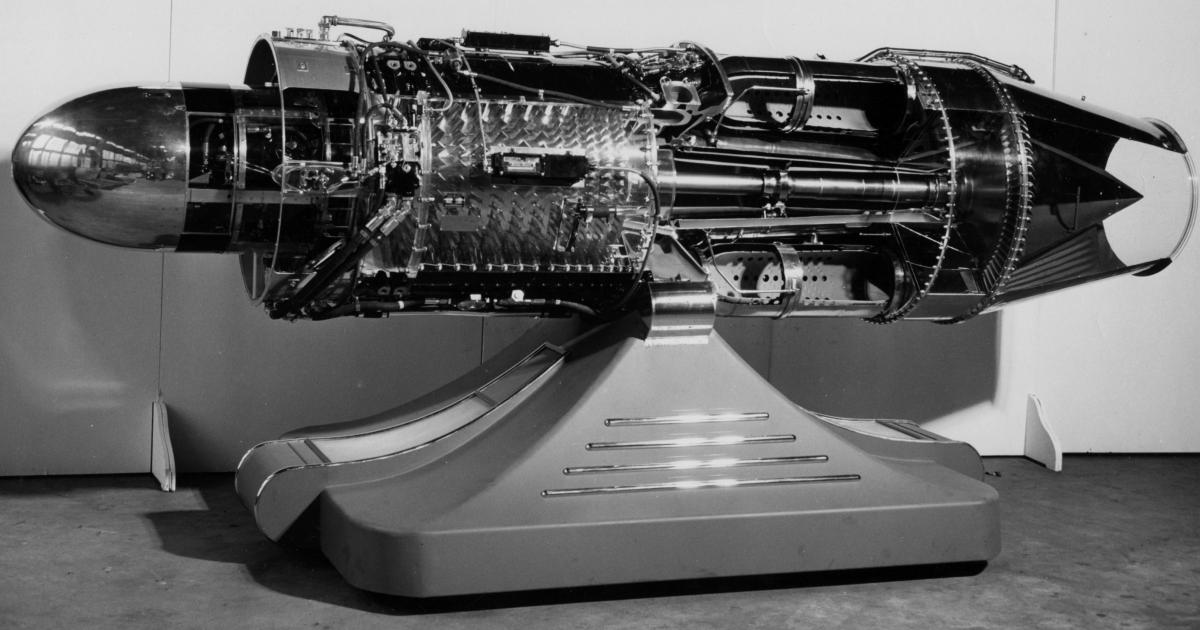
The J47 was a 5,000 – 6,000 lbT-class single-spool axial-flow turbojet developed by the General Electric Company from its J35. It first ran on 21 Jun 1947. It was about 145" long, 37" in diameter, and weighed about 2,554 lb. It burned JP-1, JP-2, JP-3, JP-4 or aviation gasoline and had an overall pressure ratio of 5:34:1. With water injection, it was capable of nearly 7,000 lbT. This article covers J47-GE-23, -25, -25A and -27 engines manufactured by General Electric Company of Evendale, Ohio, J47-ST-25 and -25A engines manufactured by Studebaker Corporation of South Bend, Indiana, and J47-PM-25 and -25A engines manufactured by Packard Motor Company, Detroit, Michigan. |
|
 |
 |
|||||||||||||||||||||||||||||||||||||||||||||||||||||||||||||||||
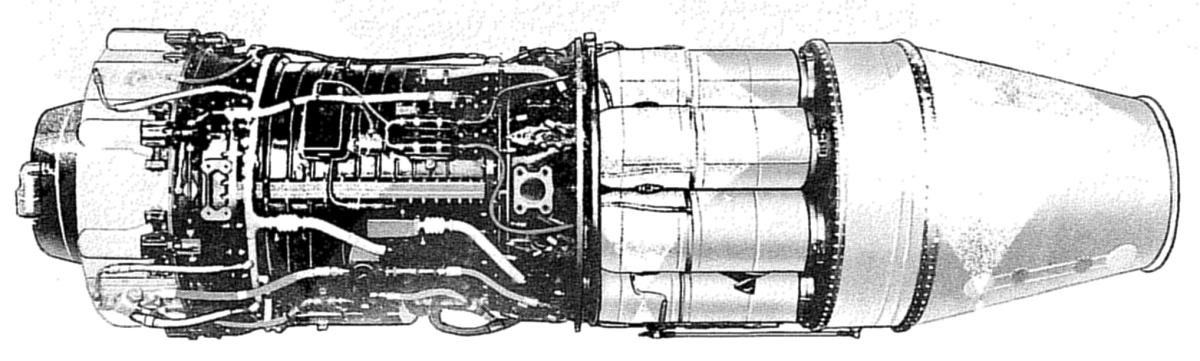
| J47-23, Left | J47-23, Right | ||||||||||||||||||||||||||||||||||||||||||||||||||||||||||||||||||
 |
 |
||||||||||||||||||||||||||||||||||||||||||||||||||||||||||||||||||
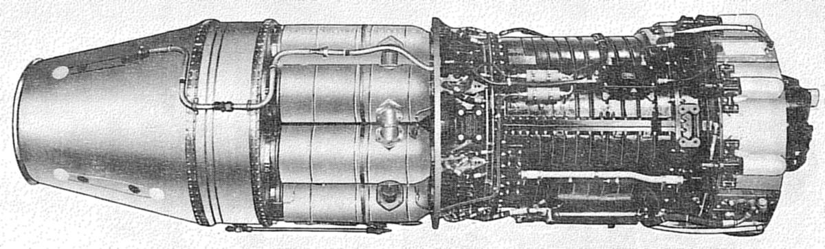
| J47-25, -25A, Left | J47-25, -25A, Right | ||||||||||||||||||||||||||||||||||||||||||||||||||||||||||||||||||
 |
 |
||||||||||||||||||||||||||||||||||||||||||||||||||||||||||||||||||
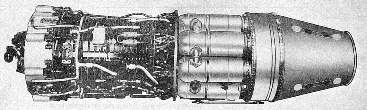
| J47-27, Left | J47-27, Right |
Overall Engine
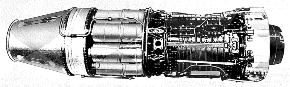
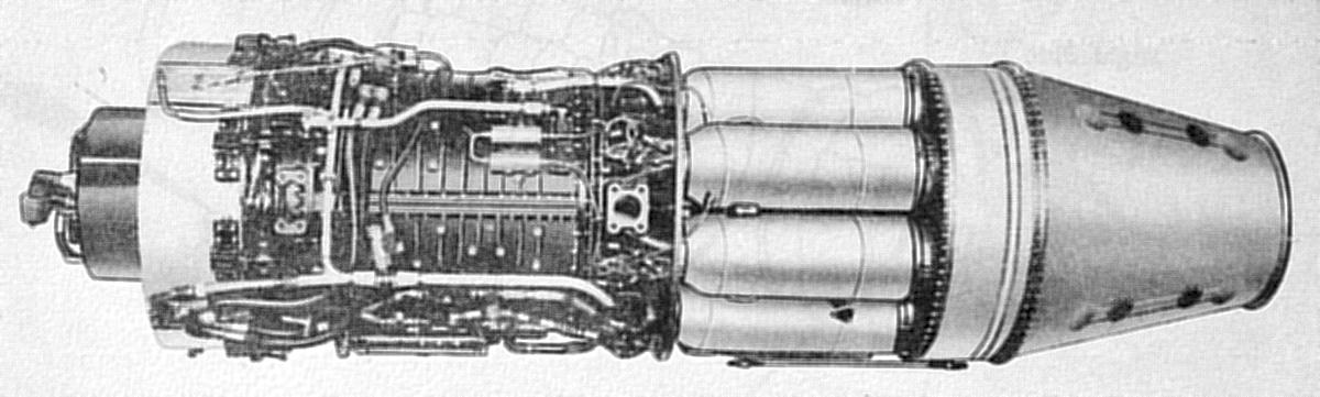
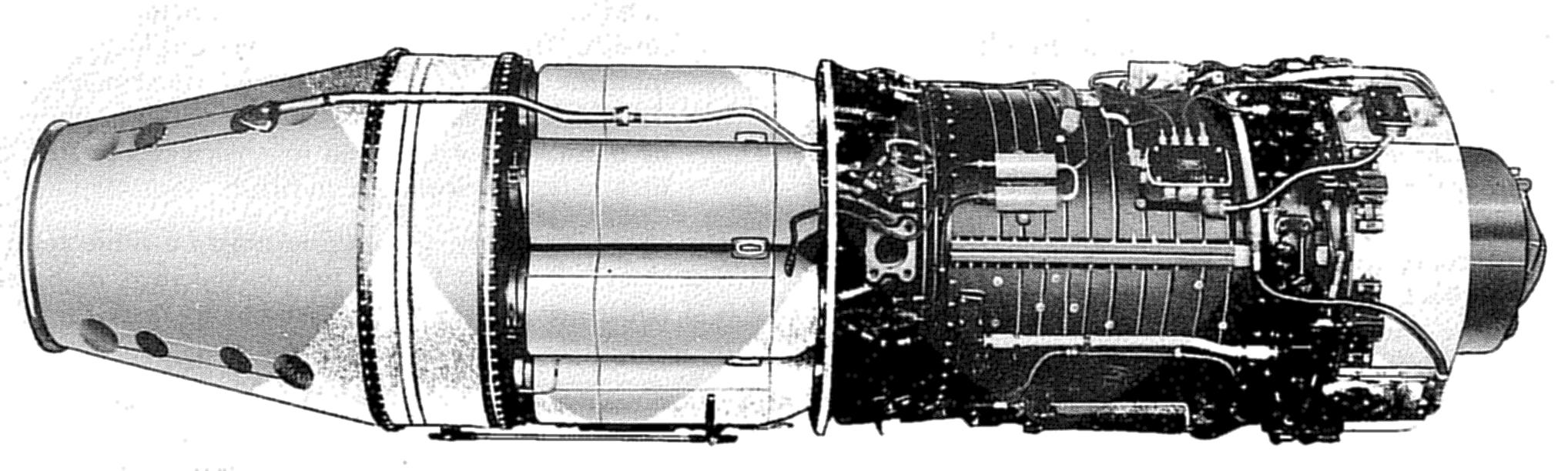
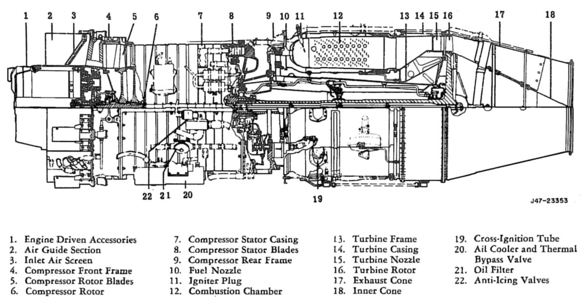
The J47 consists of a 12-stage axial-flow compressor, a set of through-flow combustion chambers, a single-stage turbine, and a fixed opening exhaust nozzle. The compressor and turbine shafts are joined with a spline-fit and locked with a turbine shaft tie-bolt. The main shafts and rotors are supported by four anti-friction bearings. The No. 1, or front, bearing is located at the compressor rotor front; the No. 2, or mid-bearing, is located at the compressor rotor rear; the No. 3, or damper, bearing is located at the turbine shaft middle; and the No. 4, or rear, bearing is located at the turbine shaft rear just forward of the turbine wheel. The No. 2 bearing is a ball (thrust) bearing; the others are roller bearings.
At the time of engine shipment, the alternator drive is not installed on the J47-23, -25 and -25A engines. For engine installation in the B-47 aircraft, power take-off kits are provided for both inboard and outboard locations. The inboard kits have a 10" alternator mount casting (without bearing or drive assembly) for supporting accessories and mounting the bullet nose. The outboard kits have an alternator mount with bearing and shaft assembly. The alternator is driven through a shaft splined to the compressor rotor.
J47-27 power take-offs consists of a hydraulic pump drive housing, gears and bearings, a splined drive shaft, supporting legs, and a cowling. Fluid power pumps are mounted on two pads on the housing front face. All engines have a cowling support between the auxiliary drive gear case and the compressor front frame. This support encloses the engine-driven accessories and forms the inner shell of the inlet air guide.
 |
 |
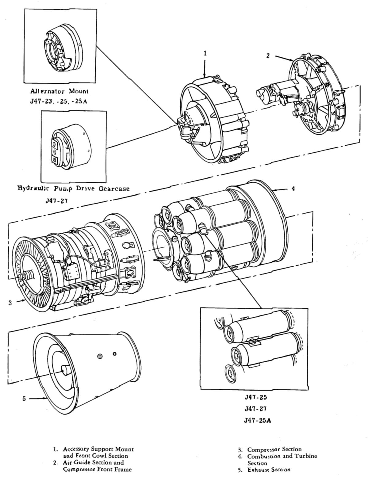 |
| J47 Nomenclature | J47 Cutaway | J47 Components |
Major Engine Components
The air guide section consists of island covers, island fairings, air, guide sectors, and a set of retractable inlet screens. This section directs air into the compressor inlet. The fairing-covered islands are utilized as passageways for lube oil, fuel, anti-icing air, hydraulic fluid, electrical lines, and a throttle linkage. The island covers are used as junction points for these lines. The island sectors, installed between the island covers, form the outer shell of the inlet air guide.
The compressor front frame assembly includes accessory drive gears and mounting pads, support and seals for the No. 1 bearing, and the inlet guide vane. The front frame consists of inner and outer sections connected by eight struts. Support for the drive gears, shaft housing, No. 1 bearing housing, and allied parts is provided by the inner section. There are four engine mounting pads on the compressor front frame, two on the horizontal and two on the vertical centerlines.
Inlet guide vanes are hollow blades or vanes mounted between two concentric rings. The vane assembly is attached to the compressor front frame rear side inner section together with a first stage compressor rotor wheel air seal shelf. The area between the front frame assembly rear face and the compressor first stage wheel forward face forms the balance-piston air chamber. This chamber is supplied by air from the twelfth stage of the compressor through the inlet guide vanes and counteracts some of the rotor forward thrust.
J47s have two types of compressor rotors. Early engines had a shaft type rotor with 12 compressor wheels shrunk onto a steel shaft. The wheels in the first 9 stages were made of aluminum; the tenth, eleventh, and twelfth stage wheels are made of steel to withstand the high temperatures and pressure at the compressor rear.
The curvic coupling compressor rotor consists of 12 wheels with a ring of gear teeth machined on both faces of the second through the eleventh stage compressor wheels. The first stage wheel rear face and twelfth stage wheel forward face also have a curvic coupling. An extension shaft on the first stage wheel front face provides a journal for the No. 1 bearing and is externally splined to drive accessory gears and accessory drive shaft by means of couplings. The twelfth stage wheel rear face is extended to form a journal for the No. 2 bearing and is internally splined to receive the turbine rotor shaft. On the curvic coupling compressor rotor the first, ninth, tenth, eleventh, and twelfth stage wheels are steel and all others are aluminum alloy. The 12 wheels are held together with 12 tie-bolts.
Both types of rotors have 11 cylindrical spacer rings, one between each wheel. The rim of the wheel is secured to the spacer ring by steel pins. The compressor blades are dovetailed into the outer rim of each wheel, and the spacer rings prevent axial movement of the compressor blades.
The compressor stator is an aluminum casing split at the horizontal centerline. Dovetailed into the inside of the aluminum casings are 13 blade rings. The compressor casings are supported at the front end by the compressor front frame and at the rear by the compressor rear frame by means of bolted flanges.
The compressor rear frame center supports the No. 2 bearing and the rear face supports the combustion chambers. Equally spaced around the shell of the compressor rear frame are 8 diffuser passages that diffuse and direct the air from the compressor twelfth stage to the combustion chambers. Eight duplex fuel nozzles are mounted on pads and extend directly into the diffuser passages with their tips projecting into the inner combustion chambers. The compressor rear frame contains four engine mounting pads, two on horizontal and two on vertical, centerlines.
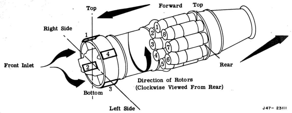
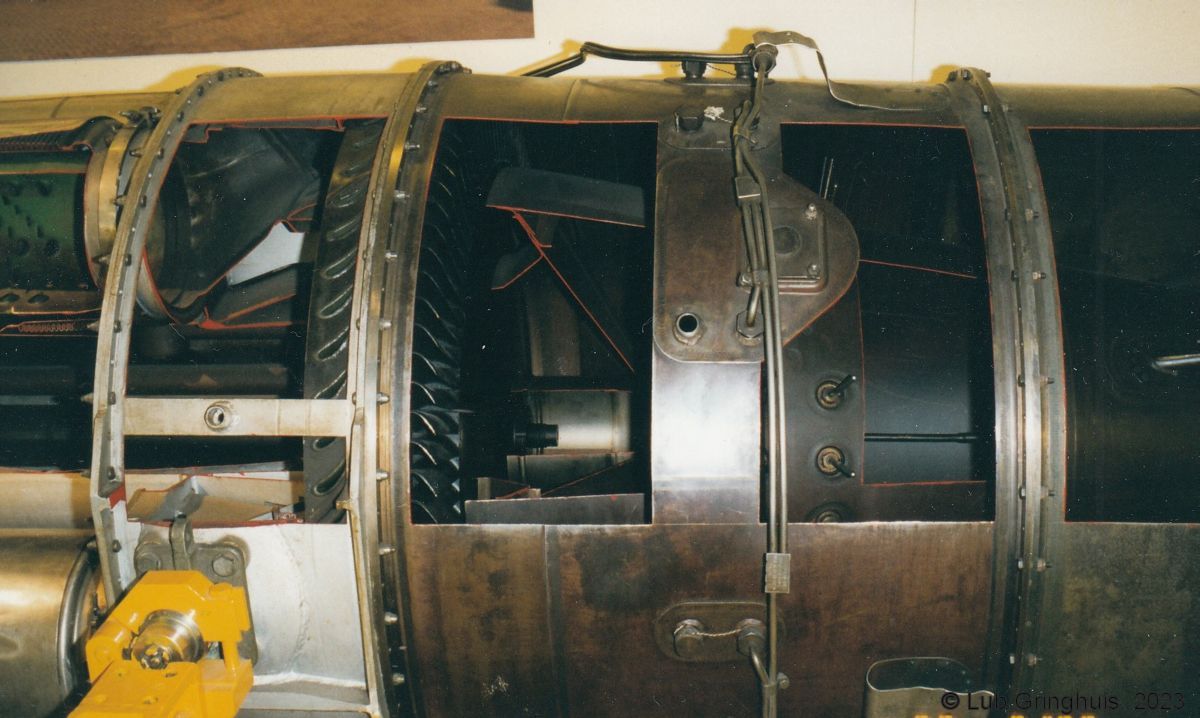
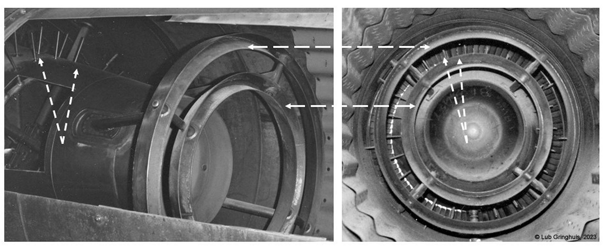
Eight direct-flow type combustion chambers are mounted around the turbine frame. Each chamber consists of a double-walled cylindrical assembly attached to the compressor rear frame and turbine frame by means of quick-disconnect clamps. Compressed air from the diffuser passages enters the combustion chambers, passes into the annular spaces between the outer casings and the inner chambers. The air is mixed with fuel sprayed from the nozzles, and the fuel-air mixture is burned. The combustion chambers are interconnected by cross-ignition tubes, which make light-off in all chambers possible, even though igniter plugs are installed in only two chambers. Eight transition liners are mounted around the aft section of the turbine frame. The function of the transition liners is to change the pattern of the exhaust gases flowing to the nozzle diaphragm. The hot gases leave the combustion chambers in eight separate circular patterns and change to an annular pattern in the transition liners.
The J47 turbine is a single-stage gas turbine of the impulse type. It consists of a turbine nozzle and a turbine rotor supported by the turbine frame and enclosed by the turbine casing, which has a shroud ring to enclose the gases as they pass through the turbine buckets. The turbine frame is bolted to the rear of the compressor rear frame. The No. 3 and No. 4 bearings are supported by the housing of the turbine frame. The hollow turbine shaft is splined at the front end to mesh with the splines of the compressor shaft. Turbine buckets are dovetailed into the wheel rim. The front and rear surfaces of the turbine rotor are cooled by air bled from the compressor. The hot gases are directed by the stationary turbine nozzle against the turbine wheel buckets. The torque transmitted to the turbine rotor drives the compressor rotor and accessories.
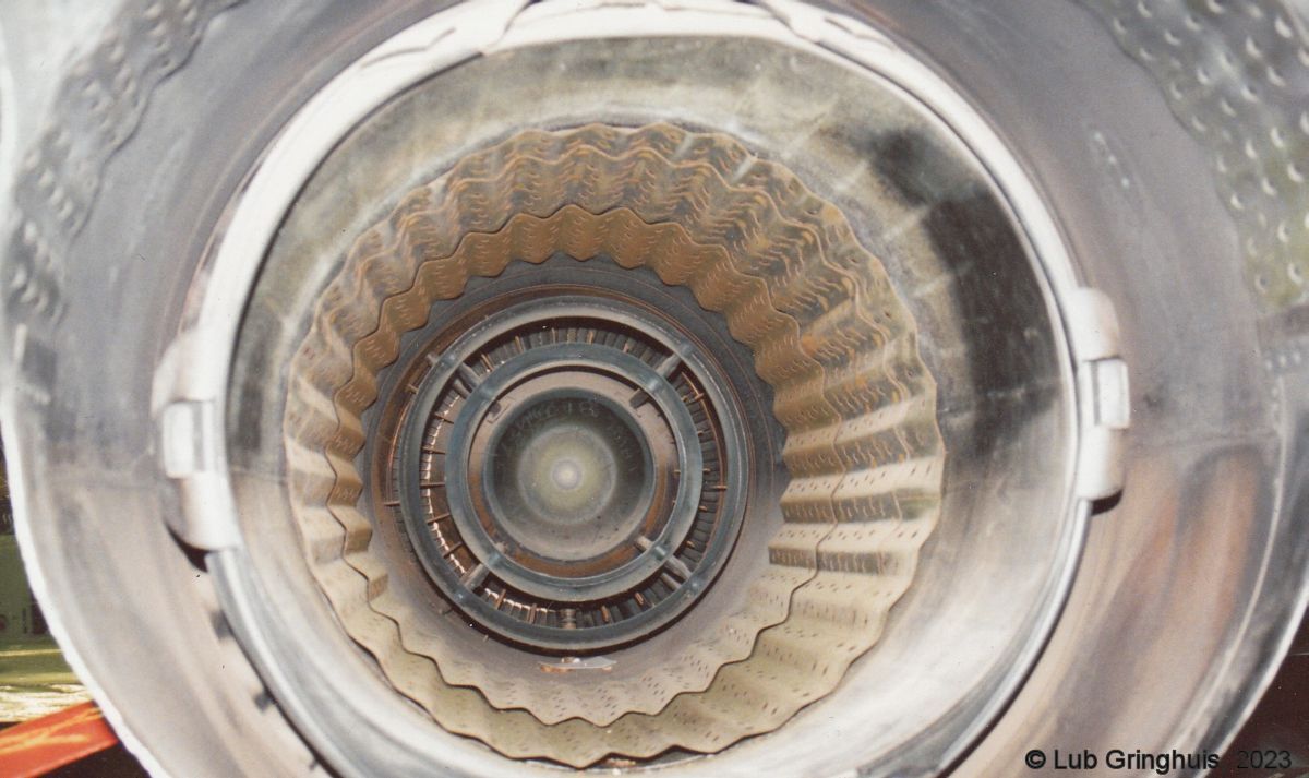
The exhaust section consists of an exhaust cone and a fixed-area exhaust nozzle. The exhaust section is bolted to the turbine casing and extends aft of the turbine wheel. After passing the turbine rotor buckets, the exhaust gases pass through the annulus formed by the outer and inner cones, and are discharged to the atmosphere through the nozzle at the rear of the exhaust pipe. Four thermocouples, wired in parallel and connected to the cockpit indicator, are installed 90° apart at the rear of the exhaust section to indicate exhaust gas temperature.
Several mounting pads on the engine may be used for installing it in a nacelle or in a fuselage. The compressor front and rear frames each have four pads located 90° apart around their circumference. On the J47-23, -25 and -25A engines, a bracket pad at the top centerline of the engine on the turbine frame burner plate is also used as a support point.
Auxiliary components mounted on pads on the forward face of the front frame are the starter-generator, the fuel regulator, the fuel pump, and the main lube and scavenge pump. The tachometer generator is mounted on the main lube and scavenge pump. The rear scavenge pump is mounted inside the compressor rear frame and is driven by the main rotor through reduction gears.
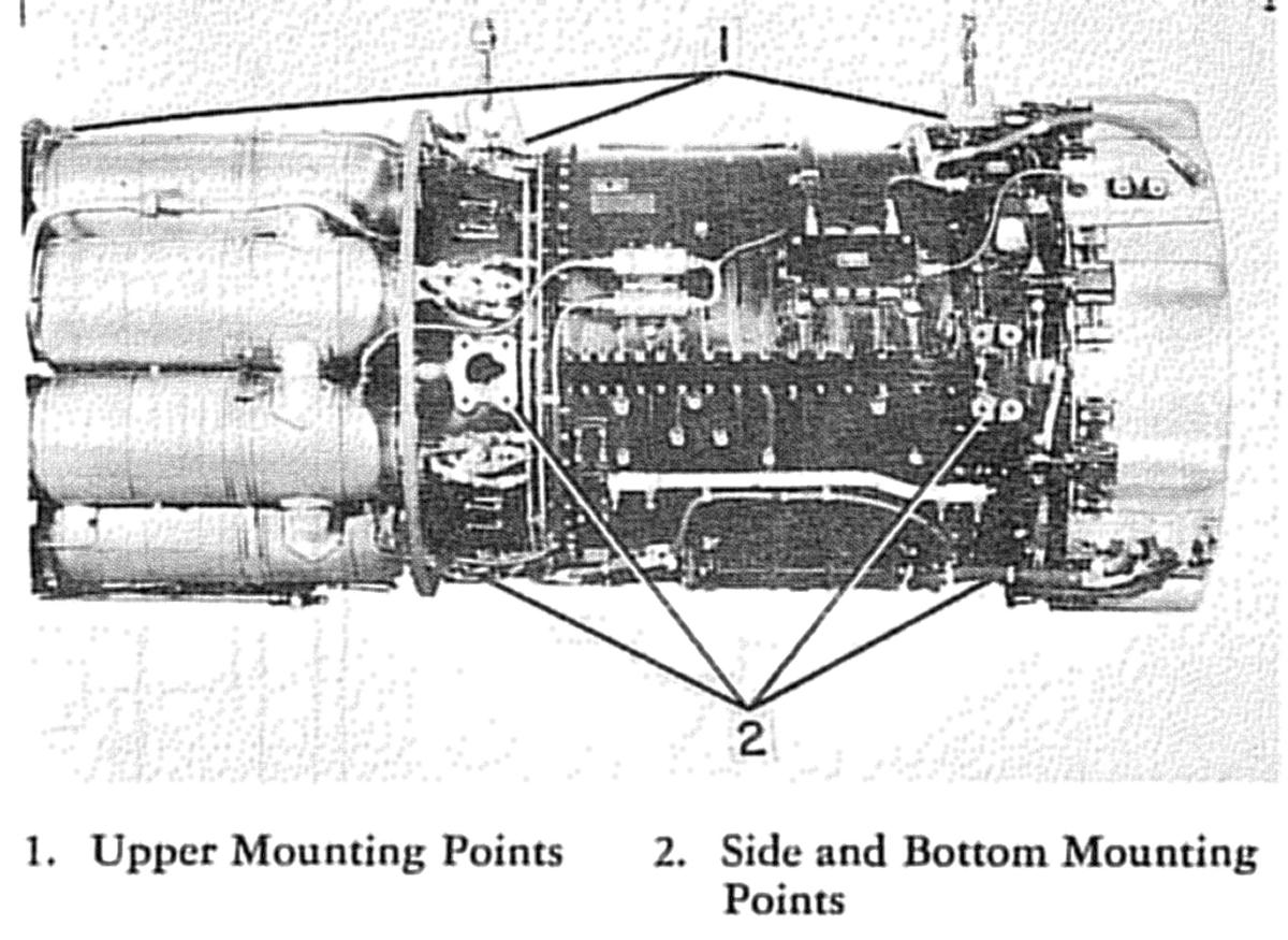 |
| J47 Mounting Pads |
Engine Systems
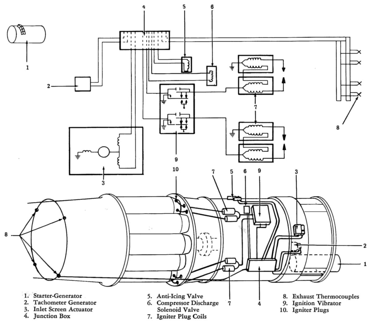
The primary function of the electrical system is to provide energy for starting and ignition and to supply power for operation of engine and aircraft electrical equipment. The starter-generator is an engine-mounted accessory, but the wiring and electrical apparatus in the starting and generator circuit are part of the aircraft electrical system. The high-voltage ignition system provides the spark necessary for starting the engine. This is a dc opposite-polarity ignition unit and consists of one dual vibrator in a single package, four separate ignition coils, four igniter plugs, and interconnecting leads. The coils are connected in pairs; one pair serves the two igniter plugs in the No. 3 combustion chamber; the other pair serves the two plugs in the No. 7 combustion chamber.
 |
 |
| J47 Electrical System | J47 Electrical System |
The positive-displacement re-circulating lubrication system supplies metered oil to cool and lubricate all bearings, gears, and the auxiliary gear case. This system also supplies oil to the main fuel regulator for hydraulic control of the main fuel system. The lubrication system consists of a pressure and scavenge pump, an oil filter, an oil cooler, and check and relief valves. In addition, a single-element, hydraulic drive scavenge pump is incorporated into the J47-27 engine.
Oil from an airframe-mounted tank enters the engine through the No. 2 island and passes to the inlet of the main pump, located on the lower left side of the accessory gear case cover. The main lube pump is a 3-element, positive-displacement, gerotor type pump with two pressure elements and one scavenge element. Oil travels from the No. 1 pressure element through the No. 3 island, through the oil filter and check valve, the pressure transmitter and compressor rear frame, to the three jets located at the No. 2, No. 3, and No. 4 bearings. There is a pressure relief valve at the discharge side of the No. 1 element to relieve high oil pressures into the compressor front frame sump in the event of a restriction in the line. Two labyrinth air and oil seals at the No. 2 and No. 4 bearings prevent oil from leaking past the bearings during engine operation. A breather mounted on the turbine frame maintains a slight vacuum within the turbine frame to control air flow across the seals and prevent leakage past the seals.
The main lube pump No. 2 supply element transfers oil at high pressure past the anti-leak valve, the relief valve and screen, and into the main gear case. Four jets lubricate the gears within the gear case and a fifth jet lubricates the No. 1 bearing. Oil is routed from the No. 2 element system through a check valve, filter, and an orifice that reduces pressure before it enters the main fuel regulator. This oil supply cools the regulator and maintains a proper oil level within it. The main fuel regulator schedules variable control oil to the fuel control valve. Oil from the main fuel regulator is returned to the system through the compressor front frame sump, which also collects scavenge oil from the accessory drive gears, No. 1 bearing, and the auxiliary drive (when used). The pressure relief valve bleeds lobe oil into the front frame sump in the event of high pressure caused by a restriction. The scavenge element of the main lube pump routes oil from the sump through the fitting in the No. 3 island to the tank.
Oil from the rear bearings is scavenged by a double-element scavenge pump in the compressor rear frame. There are two sumps for scavenging the rear bearings: one in the compressor rear frame for the No. 2 bearing, and one under the No. 4 bearing. Oil from the No. 3 bearing collects at either of the sumps, depending upon the position of the engine. An internal passage carries oil from the No. 4 bearing sump to the rear element of the scavenge pump. Scavenge oil from the No. 2 bearing is routed to the forward element of the scavenge pump through a port in the forward flange of the pump.
Scavenge oil from the rear scavenge pump flows through a check valve to the oil cooler. While passing through the oil cooler the oil is cooled by a process of heat exchange whereby the hot oil transfers a large amount of its heat to the fuel flowing through tubing within the cooler. The cooled oil then returns to the tank along with the oil scavenged from the gear case(s).
The J47-27 gear case has gears and bearings that require lubrication. The No. 2 pressure element of the main oil pump supplies this lubricating oil through a jet in the auxiliary gear case. Oil in the hydraulic pump drive gear case is scavenged through a fitting on the front frame cover by the single-element scavenge pump mounted on the rear face of the gear case and is returned to the compressor front frame. On the J47-23, -25 and -25A engines, oil is routed from the No. 2 pressure element to the bearings within the alternator drive. It drains into the compressor front frame sump and is scavenged by the main scavenge element.
 |
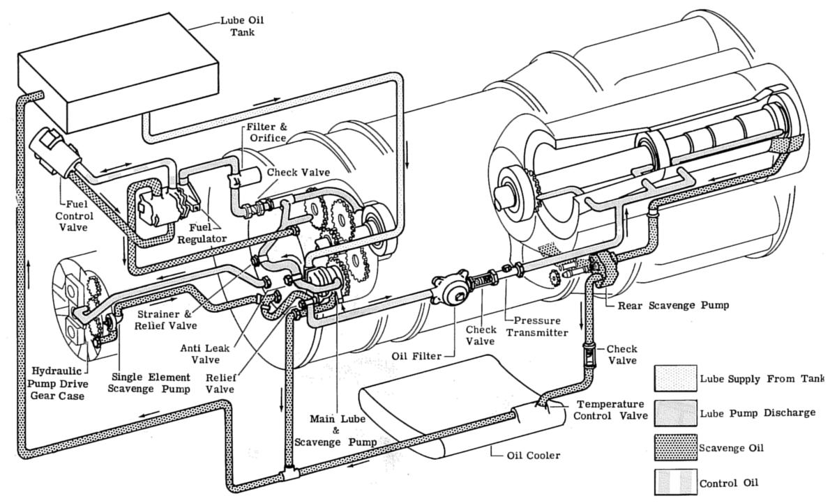 |
| J47-23,-25, -25A Lubrication System | J47-27 Lubrication System |
The J47 fuel system consists of a fuel pump, a fuel regulator, and a stopcock, all located in the front accessory section; a fuel control valve and a fuel filter mounted on the accessory mount support; and a flow divider, fuel manifolds, and fuel nozzles, all mounted on the compressor casings and the compressor rear frame. The engine fuel control system maintains proper relationship between throttle position and engine speed and controls engine operation so that rapid throttle movements may be made under all conditions.
In addition to the normal fuel system components, J47-27 engines have an emergency fuel system consisting of an emergency fuel regulator, a double check valve consisting of a main fuel check valve and a check and restrictor valve, and the emergency element of the dual element fuel pump. The emergency system supplies the engine with fuel in the event of main fuel system failure.
 |
 |
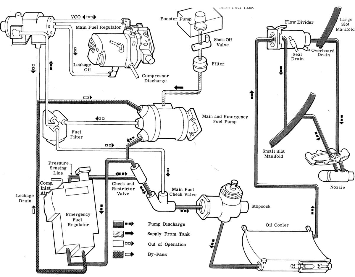 |
| J47-23,-25,-25A Fuel System | J47-27 Fuel System | J47-27 Emergency Fuel System |
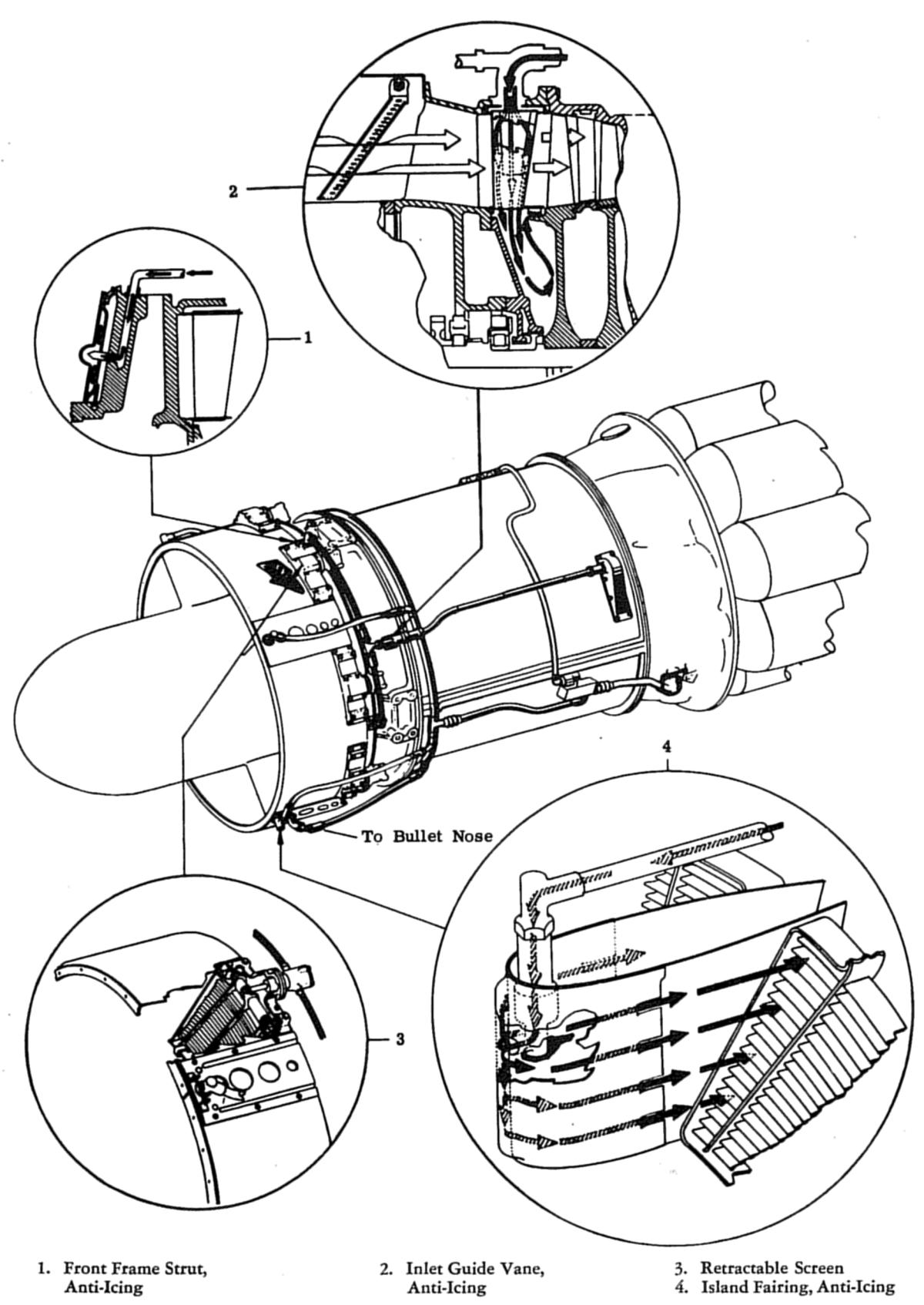
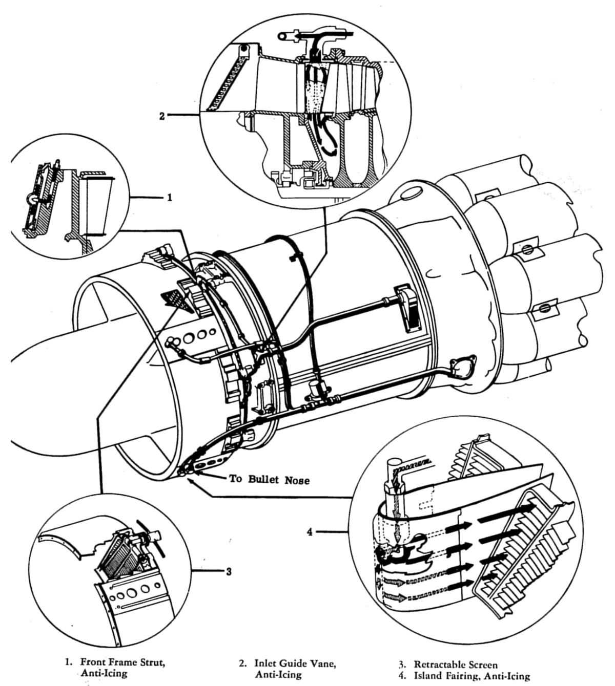
The J47 anti-icing system protects against icing by hot compressor air. The island fairings, front frame struts, inlet guide vanes, and the bullet nose, all of which are subjected to the direct blast of the cold inlet air stream, are anti-iced. The bullet nose is anti-iced by compressor discharge air taken off a pad on the compressor rear frame, brought forward into a manifold, through island No. 3 and into the bullet nose. This manifold also ducts air to the 4 island fairings. The air is led into a cavity at the leading edge of the fairing and discharged into the engine air-stream through vents at the sides of the fairings. Air for the bullet nose and fairings is controlled by a pilot-operated solenoid valve that operates the valve on J47-23, -25, and -25A engines. The J47-27 uses a butterfly-type air shutoff valve actuated by a high speed motor. In all engines, a switch in the pilot's cockpit energizes or de-energizes the air valves.
The inlet guide vanes and front frame struts not covered by island fairings are anti-iced by hot air introduced into a manifold through two elbows located 180 degrees apart on the front frame. From the manifold, the hot air passes through the 37 hollow inlet guide vanes before passing into the balance-piston area. Leakage of air from balance-piston area through the first stage seal insures a continuous flow of twelfth stage air through the guide vanes.
To prevent ice from forming on the screens, they must be retracted in flight. Eight actuators are spaced around the compressor front frame. The actuators are driven by a flexible shaft composed of eight sections, each section connecting adjacent jack screws. Each actuator has a slip clutch to assure proper functioning of the remaining screens should one become inoperative. The actuator hooks over a clevis pin on the screen; the hook is moved forward or rearward by rotation of the screen jack screw, which is driven by the flexible shaft.
A water-alcohol injection system increases takeoff thrust. The primary components of this system are a tank, a turbopump, an air valve, a pressure switch, check and drain valves, an exhaust pipe tab actuator, and injection nozzles. Control is electrical, with the main control switch located in the cockpit. All components of the system, except the water-alcohol manifold and injection nozzles, the check valve just forward of the manifold, and the tab actuator, are airframe-mounted.
 |
 |
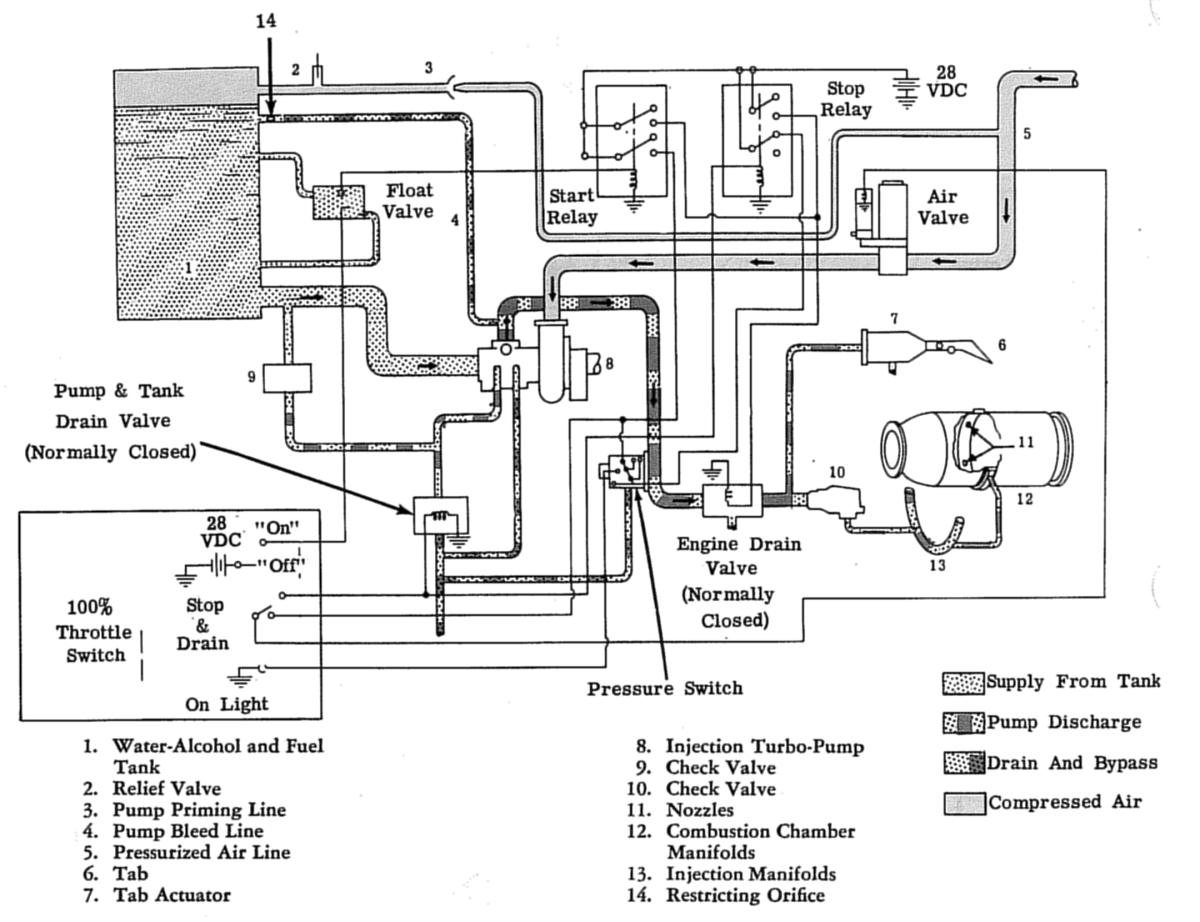 |
| J47-23,-25,-25A Anti-Ice | J47-27 Anti-Ice | J47 Water/Alcohol Injection |
The cooling system absorbs excess engine heat by ram air. Air enters through an annulus, surrounds the air inlet and compressor sections of the engine, and passes out the rear end of the engine compartment. Air ducted into the aft section of the fuselage or nacelle surrounds the combustion and exhaust sections of the engine and passes out the rear end of the nacelle or fuselage. The turbine wheel is cooled by air bled from the compressor. An air line from the eighth stage of the compressor directs cooling air to the front face of the turbine wheel. A second air line extracts air from the twelfth stage of the compressor and directs it into the inner exhaust cone to cool the rear face of the turbine wheel.
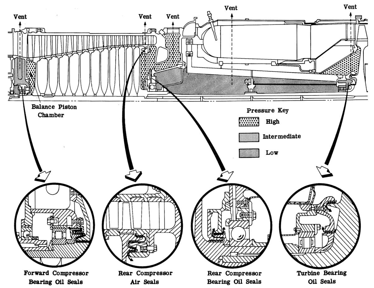
The vent system is designed to maintain proper pressures on the three engine air-oil seals. The No. 1 bearing air-oil seal is vented through four screened ports on the compressor front frame to the cooling air flowing past the engine. The No. 2 bearing seal is vented through two ports on the horizontal centerline in the rear of the compressor frame. These vents discharge into the region around the forward ends of the combustion chambers and into the cooling air flow. The No. 4 bearing is vented in a similar manner. The air is routed from the seal to two sets of perforations at the rear of the turbine frame forward of the combustion chamber support plate.
The No. 2 and No. 4 bearing seals, together with the turbine frame barrel, form a closed space containing lube oil vapor and air. This space has a vent, called the turbine frame breather, to prevent pressure buildup in the turbine frame, which would force oil out through the No. 4 bearing seal. The turbine frame breather is brought out between the No. 5 and 6 combustion chambers and must be provided with an aspirator so that a slight negative pressure differential exists between the turbine frame barrel and ambient nacelle pressure.
The drain system disposes of unused fuel in the combustion chambers and fuel and oil leakage from the accessories. Unused fuel in the combustion chambers drains through a yoke piping system that connects the forward ends of the chambers and leads to a fitting underneath the lower combustion chambers. The rear end of each chamber drains into the bottom of the turbine casing, where a drain fitting is provided. This fitting is piped to the forward combustion chamber drain so that the connection to an overboard drain may be made at either of these two points. Immediately above, and slightly forward of, the turbine casing drain, another fitting is located. This fitting can also drain the turbine casing when the engine is nose-down. This fitting is also connected to the forward drain.
Leakage from the stopcock and fuel pump is piped to a tee fitting inside the accessory gear cowling and from there through the No. 3 island fairing to an, elbow on the No. 3 island cover. The emergency fuel regulator, mounted on the upper left section of the compressor casing on the J47-27 engine, drains to a tee fitting slightly aft of the No. 3 island. The flow divider, mounted on the oil cooler, has an internal drain that returns leakage fuel to the fuel inlet fitting at the No. 3 island. The drip valves drain overboard.
The accessory section is drained through a scupper, or passage into a hollow strut of the forward frame. A drain manifold on the bottom of the compressor front frame collects the leakage from the accessory section, emergency fuel regulator, stopcock, and fuel pump, and drains it overboard. The No. 1 bearing air oil seal drains into a fitting on the bottom of the compressor front frame. This drain disposes of any condensed oil vapor in the area between the labyrinth seals.
Provision is made for drainage connections for the customer-provided hydraulic pump that may be installed on the accessory drive section or on the power take-off section of the J47-27 engine. An elbow fitting on the No. 2 island cover is provided for external connections.
 |
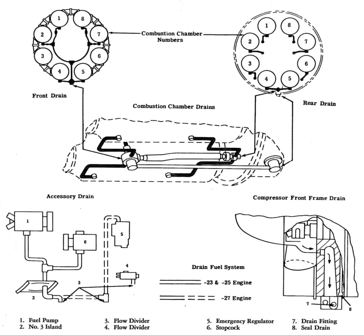 |
| J47 Internal Airflow | J47 Drains |
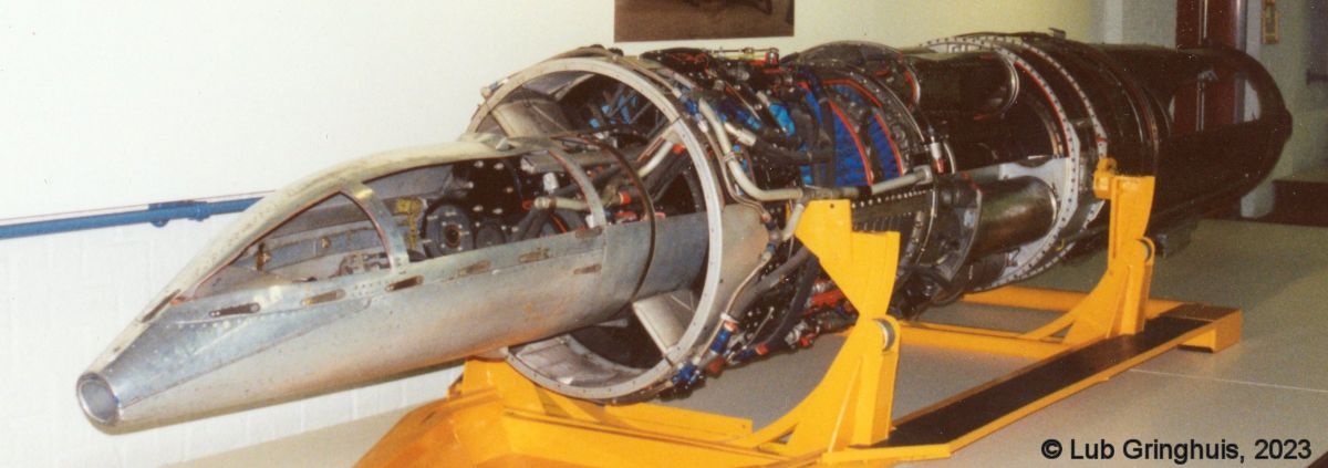
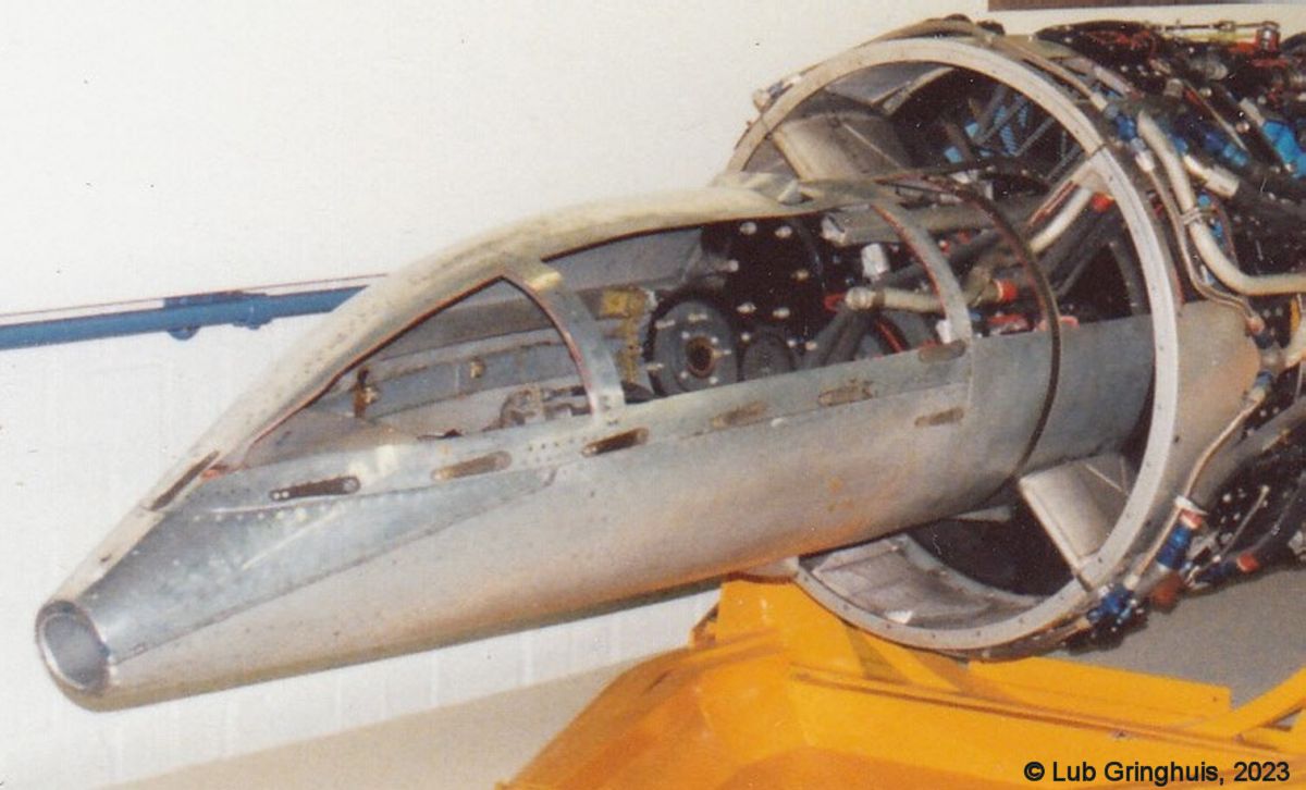
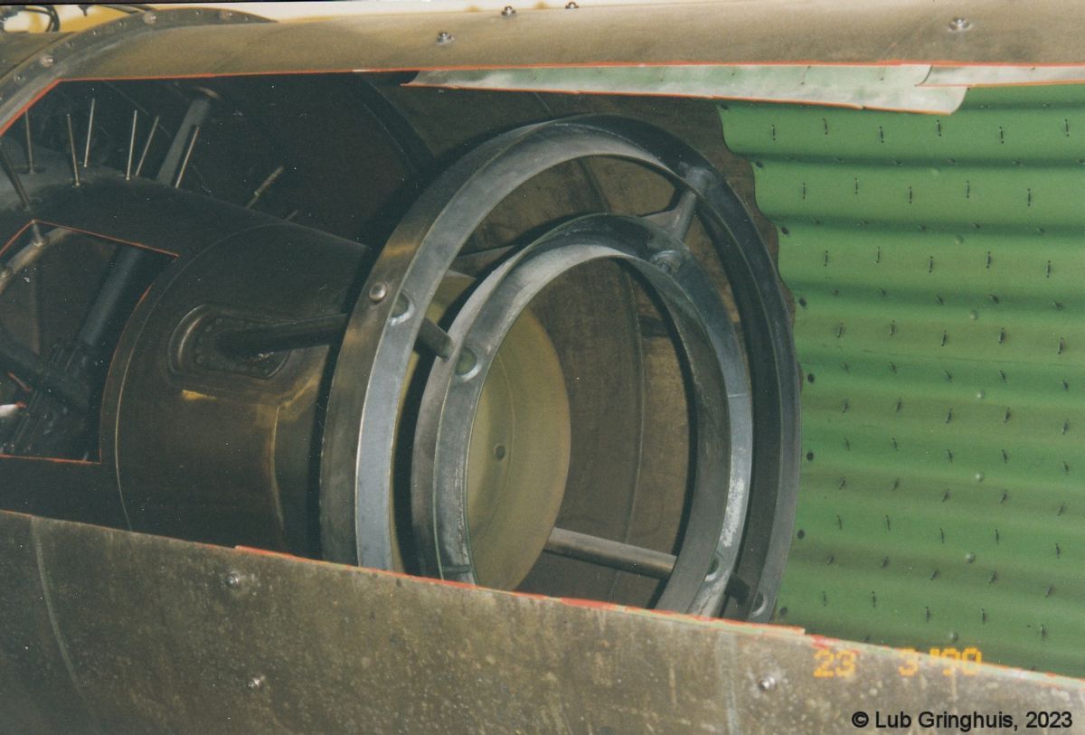
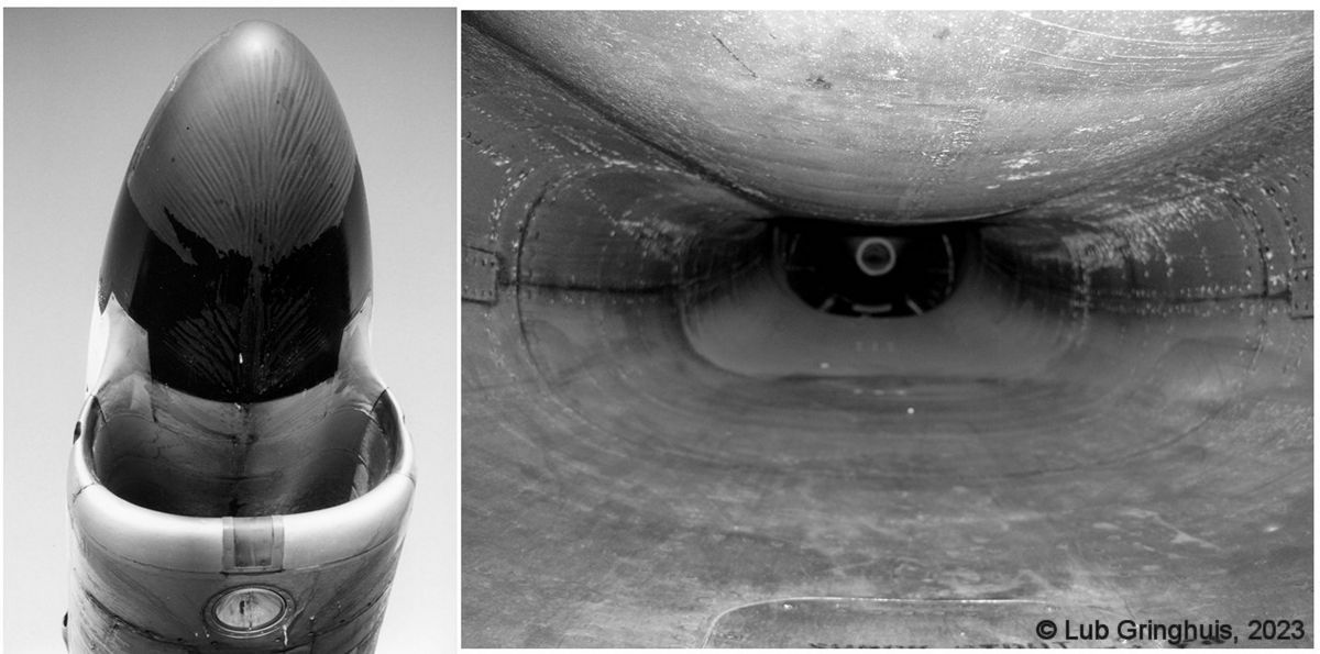 North American F-86K Inlet |
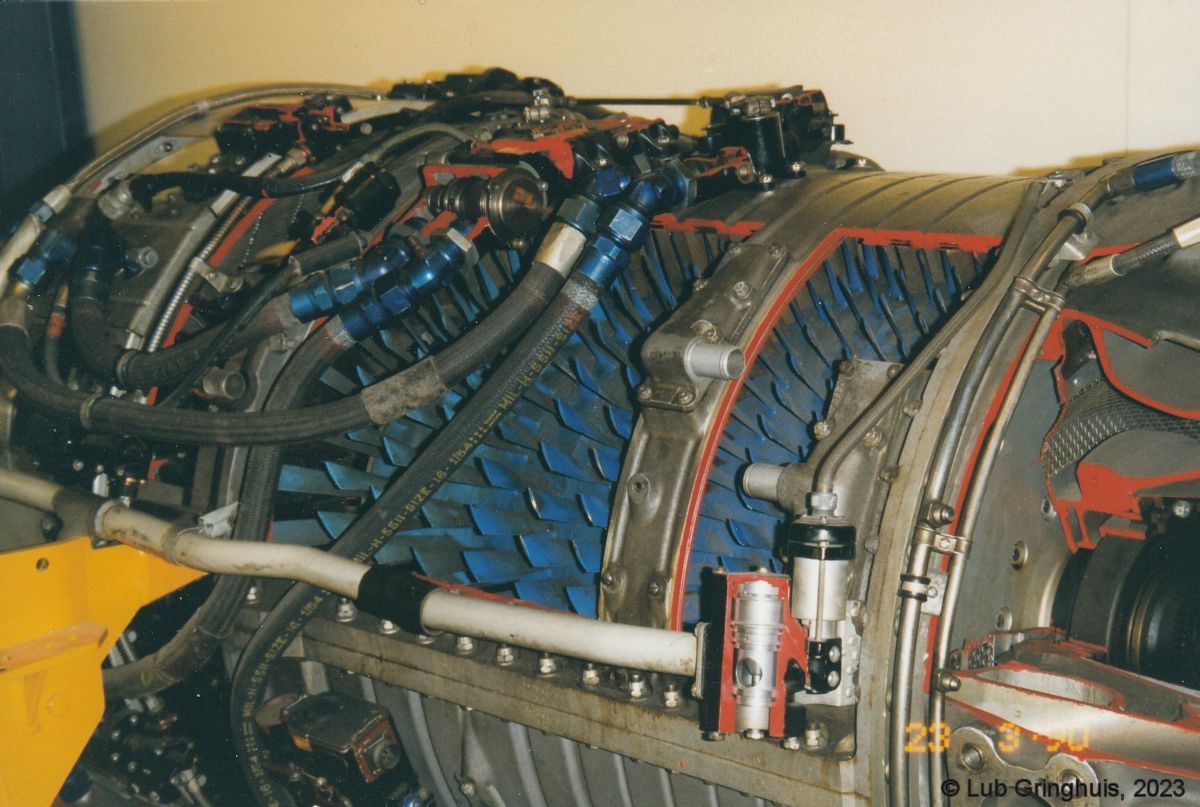
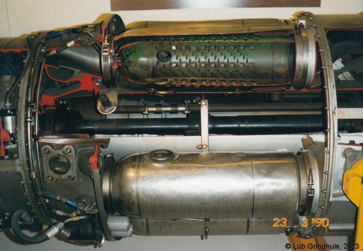
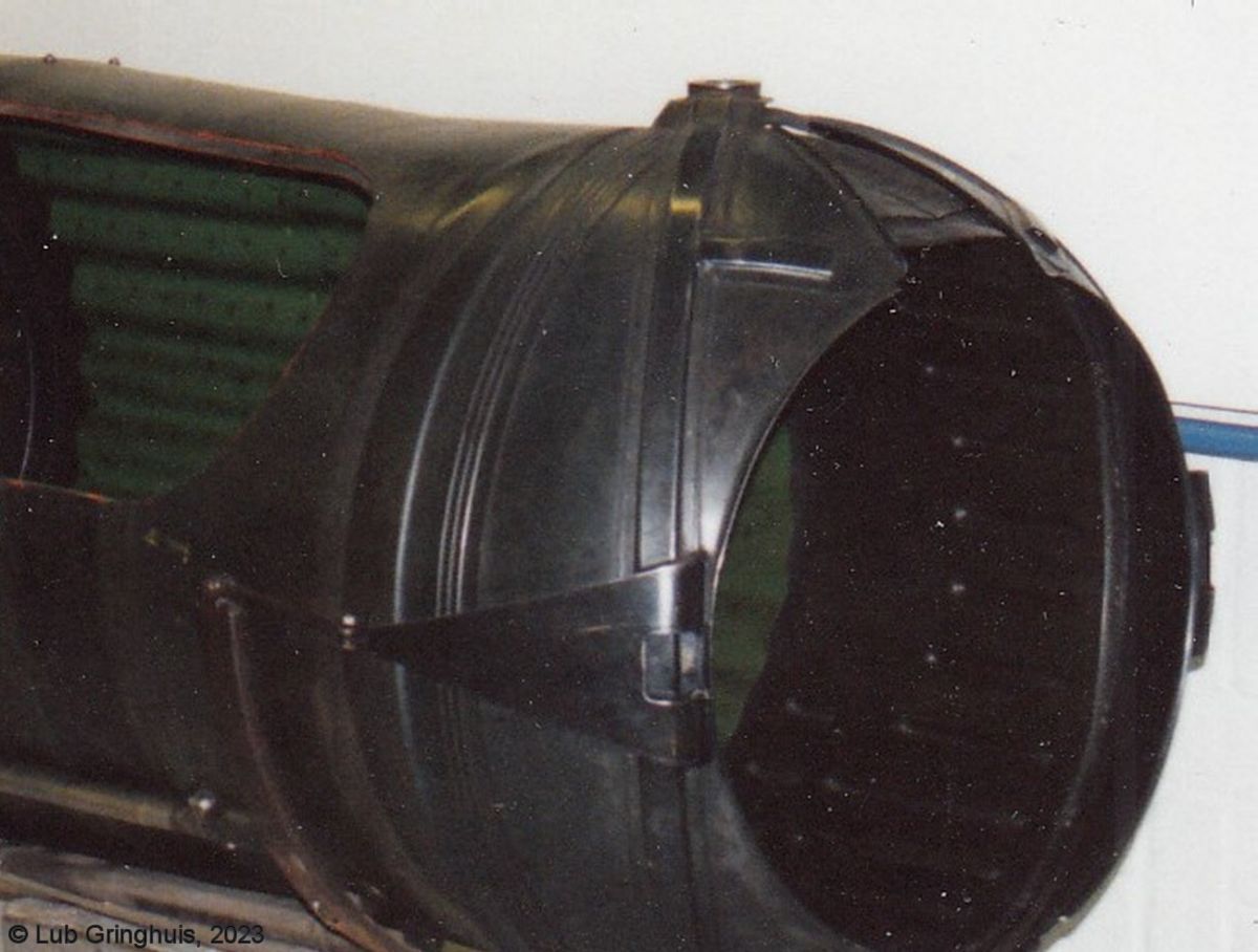
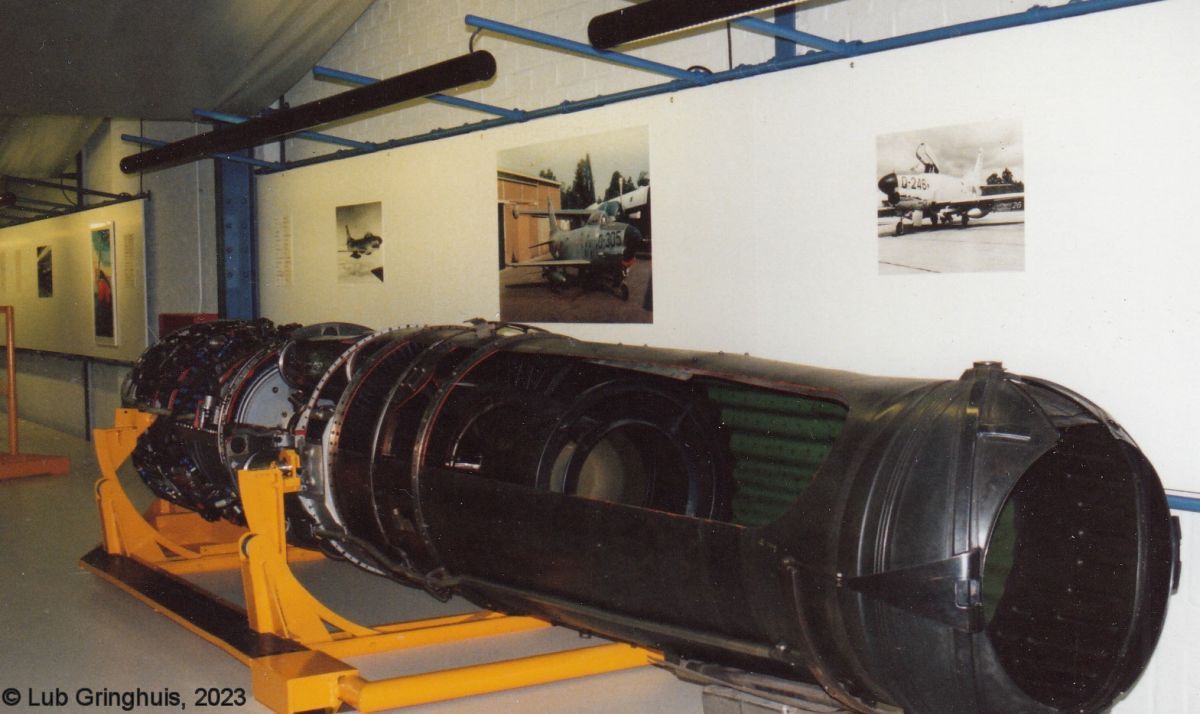
General Electric J47-GE-17B images, mostly taken by Lub Gringhuis at the Royal Netherlands Air Force Museum. Two images are courtesy of the National Institute for Military History (NIMH) This engine powered the North American F-86 Sabre. |
 |
 |
 |
 |
 |
 |
| Front Quarter | Auxiliaries | Compressor | Combustion Chamber | Turbine, Afterburner | Afterburner Fuel Nozzles, Flame Holder |
 |
 |
 |
 |
 |
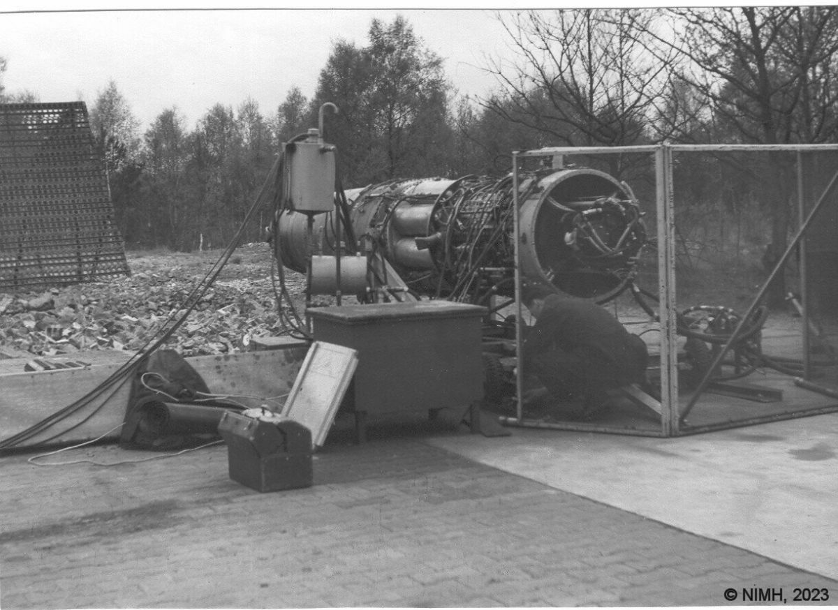 |
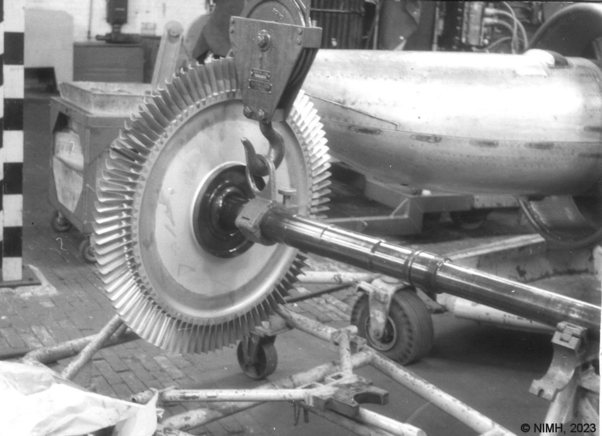
| Rotor, Turbine [NIMH] | Afterburner Ceramic Inner Liner | Afterburner Flame Holders | Tail Pipe, Nozzle | Aft Quarter | J47 Under Test [NIMH] |
Send mail to
![]() with questions or comments about this web site.
with questions or comments about this web site.
![]()