
A Brief History of Aircraft Carburetors and Fuel Systems
Part 11: Priming Systems, Anti-Detonation Injection, Summary
by Terry Welshans
Bardstown, Kentucky
for the Aircraft Engine Historical Society
August 2013
Table of Contents
There are two types of engine priming systems. Manual priming systems are found on aircraft with low horsepower engines and use a hand-operated pump located in the cockpit. This system is in common use on most carbureted general aviation engines. The priming system draws fuel from the fuel tank selector switch or from the fuel line leading to the carburetor. The manual fuel pump may be a plunger-type pump where the pilot first unlocks the pump handle located on the instrument panel, then pulls the handle out of the pump to the stop. The pilot then pushes the handle in, spraying fuel into the intake manifold. Follow the engine and aircraft manuals for the number of pump strokes for the air and engine temperatures.
Most World War II era cargo and combat aircraft employed electric priming systems. The electric primer uses fuel from the electric in-tank pumps, powered by the aircraft's battery system through a priming switch in the cockpit. Activating the primer requires care, as fuel may flood the engine if the pump is improperly used. Follow engine and aircraft manuals for the proper use of the electric primer system. The electric primer may be mounted either as a part of the carburetor or on the firewall of the aircraft, in which case the primer is not considered a basic part of the carburetor. Regardless of primer installation, leaking primers or primers with control valves stuck in the open position will result in rich mixtures, which may be mistaken for rich carburetor operation. If the primer coil burns out or the valve is stuck in the closed position, it will not be possible to obtain an engine start by use of the primer with the prescribed starting method. In all instances with electric primers, check the primer for proper operation by disconnecting the primer line at the primer outlet fitting and, with fuel booster pump on low, engaging the primer. Fuel should spray in a steady stream of from the primer fitting when energizing the primer, and no flow should occur when the primer switch is off. Replace the primer assembly if it does not operate properly.
High performance engines can only produce maximum power when the fuel-air mixture is greatly compressed. For that reason, engines with a two-stage supercharger or a turbocharger-supercharger combination operate with a risk of damage when the throttle is fully open. As stated previously, carburetors enrich the mixture at high power levels to prevent detonation as the extra fuel cools the fuel-air mixture. This rich mixture, although necessary, does not produce the full horsepower that a leaner mixture is capable of providing. One method that allows engines to produce maximum power adds a cooling fluid to the mixture, and at the same time, leans the mixture to produce the best combustion possible. With the optimal mixture, lowering the temperature of the mixture entering the engine cylinder prevents detonation. This equipment is called an anti-detonation system, often abbreviated as an ADI system, and ADI fluid, which is a mixture of water and methyl alcohol, the system is often referred to simply as water injection.[167]
Basic Requirements
Current water injection systems cut in at a predetermined manifold pressure and deliver a definite ratio of water to air to the engine for power settings above the cut-in speed. At the same time, the carburetor is deriched (leaned) by actuation of the carburetor derichment valve and the manifold pressure increases by means of a turbo reset system, or by cutting in a second speed engine-driven impeller. As a result, the fuel-air mixture leans out to true best power, the ADI fluid cools the fuel mixture and the manifold pressure increases. This combination of these events produces increased engine power.[168] To eliminate damage to the engine when the fluid supply is exhausted, a cutout arrangement returns the carburetor to normal fuel-air mixture and decreases the manifold pressure to normal when the fluid tank runs dry.
On current water injection systems, the fluid sprays into the fuel transfer line that is located between the carburetor and the fuel discharge nozzle or impeller fuel feed valve. With this arrangement, fuel tends to replace the fluid in the fluid transfer line between the fluid regulator and the fuel transfer line. Hence, there is an excessively rich mixture because there is fuel in the water transfer line that moves into the fuel transfer tube immediately before fluid injection starts. This excessively rich mixture makes the engine hesitate for a short period, immediately preceding the boost in power. For this reason, power settings used for take-off should be below the water injection cut-in manifold pressure. It is essential that all parts of this system be in proper working condition to insure availability for war emergency power when required, with a minimum danger to the engine.[169]
Water injection systems could use water as the anti-detonate fluid. However, water would freeze in the system during cold weather and at high altitude. Therefore, the preferred fluid is a water-alcohol mixture, chosen because of its anti-freeze characteristics. Once the anti-detonation mixture was adopted and the water injection system calibrated for it, no other mixture could be used.[170] Use of the water alone (in the present systems) may result in serious damage to the engine from detonation. Therefore, use the mixture prescribed in the aircraft handbook even though there is no danger of freezing with water. When removing the flow control valve for service on aircraft equipped with this system, make the cockpit control switch inoperable. Energizing the pump when the flow control valve is removed discharges ADI fluid into the engine, resulting in serious engine damage.
Operating on the best power mixture, the engine develops more power even though the manifold pressure and rpm setting remain unchanged. In addition, increased manifold pressure, up to a point that causes detonation without injection of the water-alcohol mixture, is possible.Thus, the increase in power with anti-detonation injection is two-fold: the engine operates on the best power mixture and the maximum manifold pressure is increased. Operation at this higher manifold pressure places heavy stresses on the engine. Use the anti-detonation injection and the increased power setting only for short periods. Once the ADI fluid is exhausted or moving the mixture control valve out of the military position, the derichment diaphragm pressure is lost, and the derichment jet opens once again for normal fuel flow.
Each individual aircraft-engine combination requires a water injection system tailored specifically for it. This tailoring takes into account the injection system units, the carburetor, the engine and the ADI fluid used.
Early ADI system caused a hesitation in engine power during the brief time required between derichment and water flow. This hesitation result in in a marked drop in engine power output as the changeover takes place. Later ADI systems incorporate anti-hesitation features, eliminating the hesitation. When the pilot moves the control to military power a switch turns the ADI system on, starting the ADI pump, producing pressure that moves a plunger within the fuel assembly that closes the passageway to the derichment jet, thereby causing a leaner mixture when the ADI fluid is in use. The very lean mixture raises the mean effective pressure within the cylinder, producing higher engine horsepower. The engine still suffers some damage resulting from the overall heating and stress caused by the production of very higher power.[171]
Typical ADI System Management (Instructions for On-Mark B-26K)[172]
The crew will monitor ADI system pressure, fuel flow, and manifold pressure and BMEP indicators when using ADI for takeoff. The crew must report any discrepancies to the pilot immediately. As the throttles advance beyond 44 ~ 48 inHgA, the ADI pressure should drop to a normal indication of approximately 22 psig, from the ADI flow. If the pressure drop does not occur in either engine, power will be reduced to dry takeoff settings (60 inHgA or 222 BMEP), and the ADI arming switch placed in the off position. If the ADI pressure drops below 18 psig during takeoff, carburetor enrichment in excess of 1,800 pph may occur, resulting in power loss as indicated by the BMEP. Place the ADI arming switch in the off position, and limit the manifold pressure to 60 inHgA.
|
| Fig. 122. Hydraulic Torque Meter |
This procedure uses the torque meter reading, given as brake mean effective pressure (BMEP). The average (mean) theoretical piston-top pressure that would result in the measured power output of an engine is the Mean Effective Pressure, and is an important value to consider when analyzing an engine. During normal engine operation, when a cylinder's air-fuel mixture ignites during the power stroke, the resultant combustion exerts pressure on the top of the piston. Since this pressure ultimately results in the movement of the piston itself, we can consider it correlated to the power output of the engine.
Calculate the Mean Effective Pressure with this formula: MEP = 150.8 x (Torque / CID)
CID is the cubic-inch displacement of the engine. If you use this formula for an engine with a displacement measured in metric cubic centimeters, you have to multiply the cubic-centimeters displacement by 0.061 to get the corresponding cubic-inch displacement value.
ADI System Development
ADI Hesitation Control
When first developed, ADI systems caused a small hesitation when activated, a fault in the design that could not be tolerated. The delay between the mixture control closing the passageway to the derichment jet and the start of ADI fluid delivery to the nozzle caused the hesitation. This early design became the Hesitating ADI Control System. Refinement eliminated the delay, and the later design became the non-hesitating type of control system. Two non-hesitating ADI systems were used, one with a constant flow and the other with a variable flow.
Non-Hesitating Constant-Flow ADI Control System
Figure 123 shows the operating principles of the constant flow ADI control system. [173] Water entering through the solenoid valve opens the spring-loaded check valve (2) but cannot pass through the metering-pressure control valve (4) until pressure builds in chamber A. This pressure opens the unmetered fuel shut-off valve (8), thereby admitting unmetered fuel to chamber B and opening the metering-pressure control valve (4) through the action of the large diaphragm.
Water then begins to flow to the engine through the control at a rate proportional to the unmetered fuel pressure, which in turn, is proportional to the mass airflow. The metering jet (5) controls the quantity of water injected into the engine. While the pressure builds in chamber A , pressure also builds in an external line, actuating the carburetor's derichment valve. The derichment valve reduces fuel flow to best power mixture setting for water injection operation.
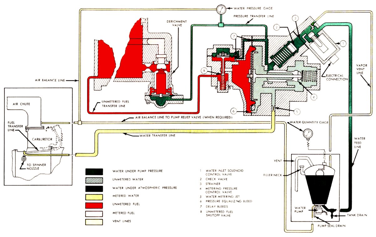 |
| Fig. 123. Non-Hesitating Constant-Flow Water-Air Control |
Non-Hesitating Variable Flow ADI Control System
Figure 124 shows the variable flow feature of the ADI control system.[174] With the solenoid in the position illustrated, unmetered fuel builds up a pressure on the diaphragm of the metering-pressure control valve (4), allowing water to enter the control. However, water does not enter the engine until sufficient metering force is present to permit the water to open the check valve (2). At a predetermined power, the check valve begins to open, giving a rapid increase in the water-air ratio as the power increases. The pressure differential caused by water flowing through the main water jet (5) acts upon the diaphragm-operated valve, causing it to open. Water pressure then builds up against the derichment valve diaphragm in the fuel control assembly. This valve then closes, reducing fuel flow through the fuel control to a predetermined setting for the best power mixture ratio.
Further increase of the pressure differential with the increased airflow causes the enrichment valve to open. When the enrichment valve is completely open, the water-air ratio is at a constant value set by the flow through the enrichment jet. This enriching action, or increase in water-air ratio, is similar to the enrichment valve and jet in the pressure-type or injection carburetor.
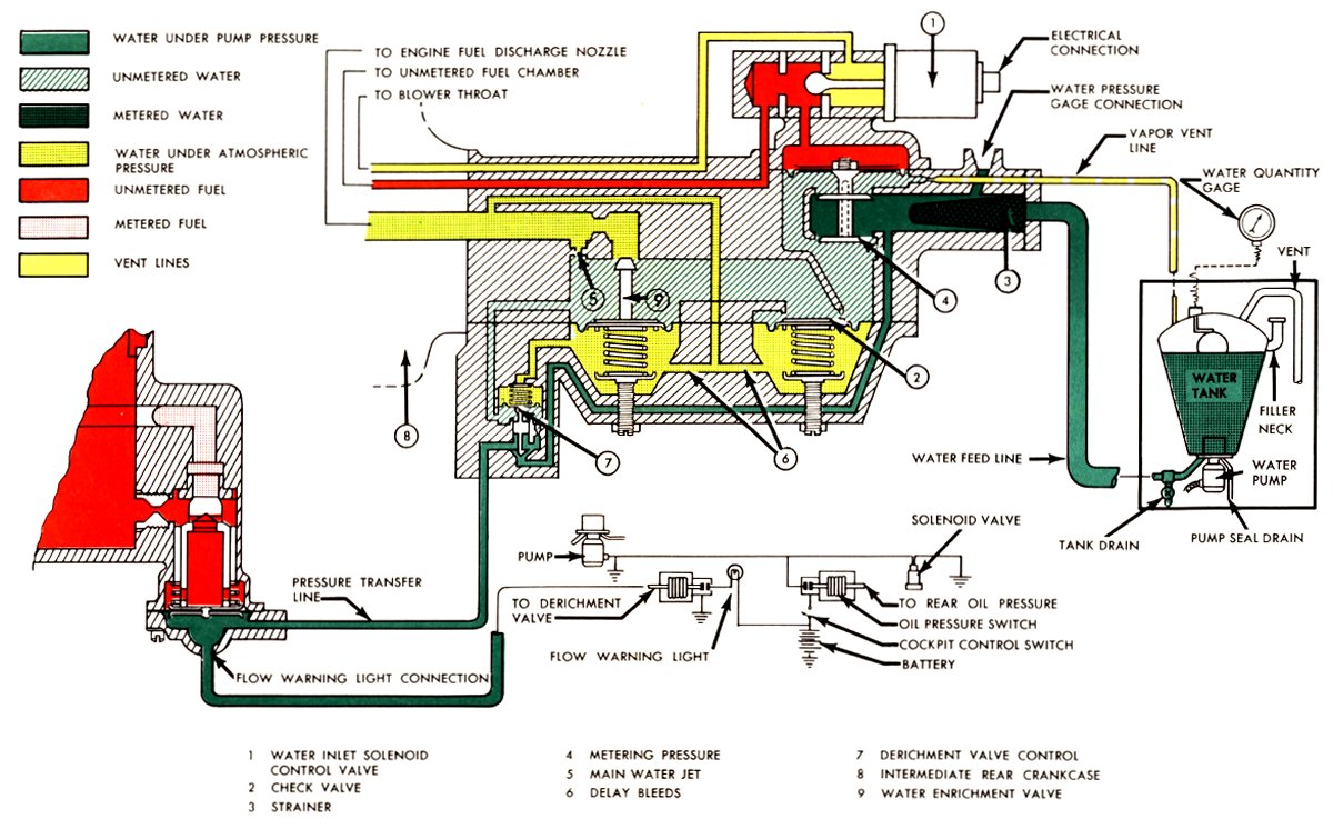 |
| Fig. 124. A Non-Hesitating Variable-Flow Water-Air Control |
The problem of obtaining accurate fuel metering for reciprocating aircraft engines was of great importance with the development of long-range, high-altitude aircraft in the 1930s and 1940s.
An analysis of aircraft carburetor design that primarily dealt with altitude-compensating systems along with a practical method of obtaining accurate altitude compensation was completed.(See NACA Technical Note 1874.)
The current development of gas-turbine engines indicates a future trend toward a wide variety of engine types.[175]
Combining the basic components of existing engines resulted in new engines and the control problems presented by each engine type differed. Eventually, it was necessary to find a general algebraic method of solving the problem of controlling gas turbine engines with any number of independent variables, and employing operational functions to describe the assumed linear characteristics for the engine, the control and other units of the system.(See NACA Technical Note 1908.)
A basic problem confronting the designer of engine controls is that of determining the dynamic behavior of the complete engine and control system under varying conditions of operation. A method of analysis to obtain the frequency response characteristics of a complete system, assuming the system is linear and provided appropriate transient data were available, was developed.(See NACA Technical Note 1935.)
Endnotes
[167] Powerplant Maintenance, pp 185-191
[168] Powerplant Maintenance, pp 185-191
[169] Powerplant Maintenance, pp 185-191
[170] Powerplant Maintenance, pp 185-191
[171] Powerplant Maintenance, pp 185-191
[172] Flight Manual USAF Series A-26A Aircraft (On Mark), p 2-11
[173] Powerplant Maintenance, p 187
[174] Powerplant Maintenance, p 193
[175] Thirty-fifth Annual Report
Send mail to
![]() with questions or comments about this web site.
with questions or comments about this web site.
![]()